EP0417350A1 - Electrical connector device to bridge line interruptions between two relatively rotating parts - Google Patents
Electrical connector device to bridge line interruptions between two relatively rotating parts Download PDFInfo
- Publication number
- EP0417350A1 EP0417350A1 EP89118947A EP89118947A EP0417350A1 EP 0417350 A1 EP0417350 A1 EP 0417350A1 EP 89118947 A EP89118947 A EP 89118947A EP 89118947 A EP89118947 A EP 89118947A EP 0417350 A1 EP0417350 A1 EP 0417350A1
- Authority
- EP
- European Patent Office
- Prior art keywords
- housing
- conductor
- rotor
- steering wheel
- lid
- Prior art date
- Legal status (The legal status is an assumption and is not a legal conclusion. Google has not performed a legal analysis and makes no representation as to the accuracy of the status listed.)
- Granted
Links
Images
Classifications
-
- B—PERFORMING OPERATIONS; TRANSPORTING
- B60—VEHICLES IN GENERAL
- B60R—VEHICLES, VEHICLE FITTINGS, OR VEHICLE PARTS, NOT OTHERWISE PROVIDED FOR
- B60R16/00—Electric or fluid circuits specially adapted for vehicles and not otherwise provided for; Arrangement of elements of electric or fluid circuits specially adapted for vehicles and not otherwise provided for
- B60R16/02—Electric or fluid circuits specially adapted for vehicles and not otherwise provided for; Arrangement of elements of electric or fluid circuits specially adapted for vehicles and not otherwise provided for electric constitutive elements
- B60R16/023—Electric or fluid circuits specially adapted for vehicles and not otherwise provided for; Arrangement of elements of electric or fluid circuits specially adapted for vehicles and not otherwise provided for electric constitutive elements for transmission of signals between vehicle parts or subsystems
- B60R16/027—Electric or fluid circuits specially adapted for vehicles and not otherwise provided for; Arrangement of elements of electric or fluid circuits specially adapted for vehicles and not otherwise provided for electric constitutive elements for transmission of signals between vehicle parts or subsystems between relatively movable parts of the vehicle, e.g. between steering wheel and column
-
- H—ELECTRICITY
- H01—ELECTRIC ELEMENTS
- H01R—ELECTRICALLY-CONDUCTIVE CONNECTIONS; STRUCTURAL ASSOCIATIONS OF A PLURALITY OF MUTUALLY-INSULATED ELECTRICAL CONNECTING ELEMENTS; COUPLING DEVICES; CURRENT COLLECTORS
- H01R35/00—Flexible or turnable line connectors, i.e. the rotation angle being limited
- H01R35/02—Flexible line connectors without frictional contact members
- H01R35/025—Flexible line connectors without frictional contact members having a flexible conductor wound around a rotation axis
Abstract
Description
Die Erfindung geht aus von einem Stromleitungsverbinder gemäß dem Oberbegriff des Patentanspruches 1.The invention is based on a power line connector according to the preamble of claim 1.
Stromleitungsverbinder der beschriebenen Art werden insbesondere zur Herstellung einer elektrischen Verbindung zwischen einer Stromquelle und der in der Lenkradschüssel angeordneten Gassack-Auffang-Schutzeinrichtung von Kraftfahrzeugen eingesetzt. Hierbei weist das im Gehäuseraum angeordnete isolierte Leiterband eine solche Länge auf, daß es dem beidseitig etwa drei Umdrehungen betragenden Lenkradausschlag zu folgen vermag, wobei sich das Leiter band während des Lenkradausschlages aus einer mittleren Lage in der einen Richtung bis zur Anlage an dem stationären Gehäuse nach außen aufweitet und in der anderen Richtung bis zur Anlage an dem Rotor nach innen zusammenzieht.Power line connectors of the type described are used in particular for establishing an electrical connection between a power source and the gas bag catch protection device of motor vehicles arranged in the steering wheel bowl. Here, the insulated conductor strip arranged in the housing space is of such a length that it is able to follow the steering wheel deflection of about three revolutions on both sides, the conductor banding itself during the steering wheel deflection from a middle position in one direction until it contacts the stationary housing expands on the outside and contracts inwards in the other direction until it contacts the rotor.
Die bekannten Stromleitungsverbinder haben sich in der Praxis gut bewährt, es wird jedoch als ein Nachteil angesehen, daß die in dem Gehäuse geführten Leiterbänder einerseits bei der normalen Lenkradbewegung Kratzgeräusche und andererseits bei plötzlichen starken Erschütterungen - etwa in Kurven oder bei Fahren auf unebenem Gelände starke Klappergeräusche abgeben.The known power line connectors have proven themselves in practice, but it is considered a disadvantage that the conductor strips guided in the housing, on the one hand, scratching noises during normal steering wheel movement and, on the other hand, strong rattling noises in the event of sudden strong vibrations - for example in curves or when driving on uneven terrain submit.
Der vorliegenden Erfindung liegt als Aufgabe die Schaffung eines Stromleitungsverbinders zugrunde, mit dessen Hilfe auf eine einfache Weise die Geräuschentwicklung verhindert werden kann. Diese Aufgabe wird mit einem Stromleitungsverbinder mit den im Patentanspruch 1 wiedergegebenen Merkmalen gelöst.The present invention has for its object to provide a power line connector, with the help of which noise can be prevented in a simple manner. This object is achieved with a power line connector having the features set out in claim 1.
Durch die Erfindung ist ein Stromleitungsverbinder geschaffen, bei dem die Geräuschentwicklung dadurch verhindert ist, daß das Leiterband zwischen den textilen Lagen geführt ist, so daß das die Schlaggeräusche verursachende Aufeinanderschlagen der Wicklungen eingedämmt wird oder allenfalls in Extremsituationen auftritt. Hierbei hat sich überraschenderweise gezeigt, daß ungeachtet der engen Führung des Leiterbandes mit seinen Kanten auf der Beschichtungslage auch über lange Zeiträume ein - ursprünglich befürchtetes - Abreiben des Textilvlieses und sich hieraus ergebende funktionelle Beeinträchtigungen nicht zu befürchten sind.The invention provides a power line connector in which the noise is prevented by the fact that the conductor strip is guided between the textile layers, so that the beating of the windings causing the impact noise is contained or at most occurs in extreme situations. It has surprisingly been found that, despite the tight guidance of the conductor strip with its edges on the coating layer, there is no fear of rubbing of the textile fleece and the resulting functional impairments over a long period of time, which was originally feared.
Weitere Ausführungsformen und Vorteile ergeben sich aus der nachfolgenden Beschreibung, in der die Erfindung anhand der beiliegenden Zeichnung beispielsweise erläutert ist.Further embodiments and advantages emerge from the following description, in which the invention is explained, for example, with reference to the accompanying drawing.
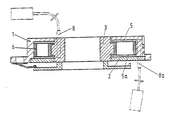
Der in der Zeichnung wiedergegebene Stromleitungsverbinder zur Überbrückung von Leiterunterbrechungen zwischen einer gestellfesten Lenksäule und einem auf der Lenksäule drehbaren Lenkrad besteht aus einem mit einem Gehäuse 1 mit Leiterabgang 8a und Deckel 2 als an der Lenksäule befestigbarer Stator sowie einem in dem Gehäuse 1, 2 drehbar gelagerten Rotor 3, der ebenfalls mit einem Leiterabgang 8 versehen ist. Das Gehäuse 1, 2 und der mit dem Lenkrad verbundene Rotor 3 umschließen einen Ringraum, der der Aufnahme eines, den Rotor in mehreren Windungen umschlingenden, in den Leiterabgängen 8, 8a endenden Leiterbandes dient.The power line connector shown in the drawing for bridging conductor interruptions between a steering column fixed to the frame and a steering wheel rotatable on the steering column consists of a stator with a housing 1 with a conductor outlet 8a and
Hierbei können die Leiterabgänge von einem Kontaktstift gebildet sein, an dem die Enden des Leiterbandes befestigt sind. Es kann jedoch auch das Leiterband 6 selbst - etwa durch Umspritzen - durch den Rotor bzw. das Gehäuse geführt sein, so daß das Leiterband selbst die Leiterabgänge bildet.In this case, the conductor outlets can be formed by a contact pin to which the ends of the conductor strip are attached. However, the
Der Boden des Gehäuses 1 und der Deckel 2 sind jeweils mit einer Beschichtung aus einem textilen Dämmstoff versehen, der von einem Poly-Äthylen-Faser-Vlies oder einem anderen geeigneten Material bestehen kann, das mit einem Bindemittel zu einem isolierenden Filz hoher Abriebfestigkeit verdichtet ist. Die Filzlage kann in beliebiger bekannter Weise, beispielsweise mittels einer Selbstklebebeschichtung auf dem Boden des Gehäuses bezw. dem Deckel befestigt sein.The bottom of the housing 1 and the
Claims (3)
Priority Applications (2)
| Application Number | Priority Date | Filing Date | Title |
|---|---|---|---|
| BR9004528A BR9004528A (en) | 1989-09-12 | 1990-09-11 | CURRENT LINE CONNECTOR TO DETERMINE THE INTERRUPTION OF CONDUCTORS BETWEEN PARTS THAT TURN ONE AGAINST THE OTHER |
| JP2241053A JP2724038B2 (en) | 1989-09-12 | 1990-09-11 | Conductive connector for bridging conductor breaks between relatively rotatable parts |
Applications Claiming Priority (2)
| Application Number | Priority Date | Filing Date | Title |
|---|---|---|---|
| DE3930494 | 1989-09-12 | ||
| DE3930494 | 1989-09-12 |
Publications (2)
| Publication Number | Publication Date |
|---|---|
| EP0417350A1 true EP0417350A1 (en) | 1991-03-20 |
| EP0417350B1 EP0417350B1 (en) | 1994-06-01 |
Family
ID=6389288
Family Applications (1)
| Application Number | Title | Priority Date | Filing Date |
|---|---|---|---|
| EP89118947A Expired - Lifetime EP0417350B1 (en) | 1989-09-12 | 1989-10-12 | Electrical connector device to bridge line interruptions between two relatively rotating parts |
Country Status (3)
| Country | Link |
|---|---|
| US (1) | US5100331A (en) |
| EP (1) | EP0417350B1 (en) |
| DE (1) | DE58907793D1 (en) |
Cited By (15)
| Publication number | Priority date | Publication date | Assignee | Title |
|---|---|---|---|---|
| DE4235056A1 (en) * | 1992-10-17 | 1994-04-21 | Daimler Benz Ag | Contact spiral for connecting steering wheel and column leads - has contact circuit board mounted to be freely accessible in open chamber in circuit board housing |
| DE4235054A1 (en) * | 1992-10-17 | 1994-04-21 | Daimler Benz Ag | Housing for contact spiral for vehicle steering arrangement - has fixing element engaging both housing sections in transport position and releasing one section and fixing other to steering for assembly |
| DE4235055A1 (en) * | 1992-10-17 | 1994-04-21 | Daimler Benz Ag | Housing for a contact spiral |
| EP0623442A1 (en) * | 1993-05-04 | 1994-11-09 | Kabelmetal Electro GmbH | Process for manufacturing a device for the transmission of signals between two terminals |
| DE4404408C1 (en) * | 1994-02-11 | 1995-02-09 | Petri Ag | Electrical lead connector for bridging conductor interruptions between parts which can rotate with respect to one another |
| EP0706914A2 (en) | 1994-10-15 | 1996-04-17 | Alcatel Kabel AG & Co. | Device for signal transmission between two extremities |
| EP1109271A3 (en) * | 1999-12-14 | 2002-01-16 | Nexans | Device for signaltransmission between two endstations |
| DE102004033024A1 (en) * | 2004-07-09 | 2006-02-02 | Nexans | Device for signal transmission between two terminals |
| EP1800957A1 (en) | 2005-12-21 | 2007-06-27 | Nexans | Device for signal and current transmission between terminals |
| EP1800956A1 (en) | 2005-11-25 | 2007-06-27 | Nexans | Device for signal and current transmission between terminal points |
| EP1808940A1 (en) | 2005-12-19 | 2007-07-18 | Nexans | Device for transmitting signals between terminals |
| EP1973205A1 (en) | 2007-03-19 | 2008-09-24 | NEXANS France | Series of devices for signal or power transmission between end points relatively rotatable between eachother |
| EP2060446A1 (en) | 2007-11-14 | 2009-05-20 | Nexans | Device for transferring electricity and/or signals between two end positions |
| EP2364882A1 (en) | 2010-03-12 | 2011-09-14 | Nexans | Assembly for electrically linking two electric contact points |
| CN109004492A (en) * | 2018-06-26 | 2018-12-14 | 伟创力电子电气(苏州)有限公司 | A kind of automatically slotting blind hole equipment |
Families Citing this family (17)
| Publication number | Priority date | Publication date | Assignee | Title |
|---|---|---|---|---|
| JP2576602Y2 (en) * | 1991-06-28 | 1998-07-16 | 古河電気工業株式会社 | Brushless electric signal device for automobile |
| DE4216526A1 (en) * | 1992-05-19 | 1993-11-25 | Kabelmetal Electro Gmbh | Signal transmitting device for cassette line in vehicle air-bag system - has spring element mounted on rotor which fixes cassette onto stator in assembly position |
| DE4329119A1 (en) * | 1993-08-30 | 1995-03-02 | Petri Ag | Power line connector for bridging wire breaks between mutually rotatable parts |
| US5460535A (en) * | 1994-02-14 | 1995-10-24 | Methode Electronics, Inc. | Two-piece clockspring with lock and wire harness assembly |
| US5487667A (en) * | 1994-03-11 | 1996-01-30 | Methode Electronics, Inc. | Automobile clockspring with vibration dampener |
| EP0762961B2 (en) * | 1994-05-26 | 2003-05-14 | ITT Automotive Europe GmbH | Steering-column switch with buffer spring |
| DE19511654A1 (en) * | 1995-03-30 | 1996-10-02 | Alcatel Kabel Ag | Device for signal transmission between two end points |
| DE19511653A1 (en) * | 1995-03-30 | 1996-10-02 | Alcatel Kabel Ag | Device for signal transmission between two end points |
| TW298660B (en) * | 1995-06-13 | 1997-02-21 | Nisshin Denki Kk | |
| JP3403560B2 (en) * | 1995-11-29 | 2003-05-06 | 矢崎総業株式会社 | Cover fixing structure to end face of cylindrical body |
| JP3403321B2 (en) * | 1997-08-08 | 2003-05-06 | 株式会社オートネットワーク技術研究所 | Cable reel provided with sound absorbing material and sound absorbing material forming method for cable reel |
| JPH1167402A (en) * | 1997-08-08 | 1999-03-09 | Harness Sogo Gijutsu Kenkyusho:Kk | Sound absorbing material, and cable reel provided with the sound absorbing material |
| DE19948724A1 (en) * | 1999-10-09 | 2001-04-12 | Eaton Corp Eaton Ct Cleveland | Method for producing a housing for an electrical connection device between mutually rotatable parts |
| DE10162127A1 (en) | 2001-12-18 | 2003-07-03 | Nexans | Electrical connector between two end points |
| US7192293B2 (en) * | 2004-10-15 | 2007-03-20 | Delphi Technologies, Inc. | Non-reversing short tape coil device |
| JP4602176B2 (en) * | 2005-07-01 | 2010-12-22 | 矢崎総業株式会社 | Rotating connector device |
| CN105416218B (en) * | 2015-12-11 | 2018-03-13 | 山西中航锦恒科技有限公司 | A kind of floated clock spring and its adjustment method |
Citations (3)
| Publication number | Priority date | Publication date | Assignee | Title |
|---|---|---|---|---|
| GB983411A (en) * | 1900-01-01 | |||
| EP0243047A2 (en) * | 1986-04-15 | 1987-10-28 | The Furukawa Electric Co., Ltd. | Connector device for a transmission line connecting two relatively rotating members |
| US4722690A (en) * | 1987-03-17 | 1988-02-02 | Methode Electronics, Inc. | Clock spring interconnector |
Family Cites Families (1)
| Publication number | Priority date | Publication date | Assignee | Title |
|---|---|---|---|---|
| JPH0636040Y2 (en) * | 1988-03-31 | 1994-09-21 | アルプス電気株式会社 | Cable reel |
-
1989
- 1989-10-12 DE DE58907793T patent/DE58907793D1/en not_active Expired - Fee Related
- 1989-10-12 EP EP89118947A patent/EP0417350B1/en not_active Expired - Lifetime
-
1990
- 1990-09-12 US US07/580,924 patent/US5100331A/en not_active Expired - Fee Related
Patent Citations (3)
| Publication number | Priority date | Publication date | Assignee | Title |
|---|---|---|---|---|
| GB983411A (en) * | 1900-01-01 | |||
| EP0243047A2 (en) * | 1986-04-15 | 1987-10-28 | The Furukawa Electric Co., Ltd. | Connector device for a transmission line connecting two relatively rotating members |
| US4722690A (en) * | 1987-03-17 | 1988-02-02 | Methode Electronics, Inc. | Clock spring interconnector |
Cited By (17)
| Publication number | Priority date | Publication date | Assignee | Title |
|---|---|---|---|---|
| DE4235056A1 (en) * | 1992-10-17 | 1994-04-21 | Daimler Benz Ag | Contact spiral for connecting steering wheel and column leads - has contact circuit board mounted to be freely accessible in open chamber in circuit board housing |
| DE4235054A1 (en) * | 1992-10-17 | 1994-04-21 | Daimler Benz Ag | Housing for contact spiral for vehicle steering arrangement - has fixing element engaging both housing sections in transport position and releasing one section and fixing other to steering for assembly |
| DE4235055A1 (en) * | 1992-10-17 | 1994-04-21 | Daimler Benz Ag | Housing for a contact spiral |
| EP0623442A1 (en) * | 1993-05-04 | 1994-11-09 | Kabelmetal Electro GmbH | Process for manufacturing a device for the transmission of signals between two terminals |
| DE4404408C1 (en) * | 1994-02-11 | 1995-02-09 | Petri Ag | Electrical lead connector for bridging conductor interruptions between parts which can rotate with respect to one another |
| FR2716301A1 (en) * | 1994-02-11 | 1995-08-18 | Petri Ag | Current conduction connection for bridging conduction interruptions between elements which can rotate relative to each other. |
| DE4404408C2 (en) * | 1994-02-11 | 2000-11-09 | Petri Ag | Power line connector for bridging wire breaks between mutually rotatable parts |
| EP0706914A2 (en) | 1994-10-15 | 1996-04-17 | Alcatel Kabel AG & Co. | Device for signal transmission between two extremities |
| EP1109271A3 (en) * | 1999-12-14 | 2002-01-16 | Nexans | Device for signaltransmission between two endstations |
| DE102004033024A1 (en) * | 2004-07-09 | 2006-02-02 | Nexans | Device for signal transmission between two terminals |
| EP1800956A1 (en) | 2005-11-25 | 2007-06-27 | Nexans | Device for signal and current transmission between terminal points |
| EP1808940A1 (en) | 2005-12-19 | 2007-07-18 | Nexans | Device for transmitting signals between terminals |
| EP1800957A1 (en) | 2005-12-21 | 2007-06-27 | Nexans | Device for signal and current transmission between terminals |
| EP1973205A1 (en) | 2007-03-19 | 2008-09-24 | NEXANS France | Series of devices for signal or power transmission between end points relatively rotatable between eachother |
| EP2060446A1 (en) | 2007-11-14 | 2009-05-20 | Nexans | Device for transferring electricity and/or signals between two end positions |
| EP2364882A1 (en) | 2010-03-12 | 2011-09-14 | Nexans | Assembly for electrically linking two electric contact points |
| CN109004492A (en) * | 2018-06-26 | 2018-12-14 | 伟创力电子电气(苏州)有限公司 | A kind of automatically slotting blind hole equipment |
Also Published As
| Publication number | Publication date |
|---|---|
| US5100331A (en) | 1992-03-31 |
| DE58907793D1 (en) | 1994-07-07 |
| EP0417350B1 (en) | 1994-06-01 |
Similar Documents
| Publication | Publication Date | Title |
|---|---|---|
| EP0417350A1 (en) | Electrical connector device to bridge line interruptions between two relatively rotating parts | |
| DE3406327C2 (en) | ||
| DE3808778C2 (en) | ||
| EP0425846B1 (en) | Current supply device between two terminals | |
| DE3541287A1 (en) | DEVICE FOR TRANSMITTING ELECTRICITY BETWEEN TWO RELATIVELY MOVABLE CONTACTS | |
| EP0031867B2 (en) | Gear-box for electrical tools | |
| DE19618958A1 (en) | Modular brush insert cassette | |
| DE4027952C3 (en) | Electrical connection device | |
| EP0224053A2 (en) | Wiring device for the motor of an electric machine tool | |
| DE10082234T5 (en) | Clock spring with non-yielding and yielding drum elements | |
| DE3906308C2 (en) | ||
| EP0886357A2 (en) | Protective sleeve for cables, strands, cable harnesses and the like | |
| DE10235862C1 (en) | Flat ribbon cable, connecting inner and outer rotating housing sections e.g. in a motor vehicle steering system, has magnetic/magnetized end zones to cling to the housing surfaces without becoming loose | |
| DE4404408C1 (en) | Electrical lead connector for bridging conductor interruptions between parts which can rotate with respect to one another | |
| EP0991151A2 (en) | Contact element to connect a flat cable to round conductors and rotary connector with such contact | |
| DE19533439C1 (en) | Connecting device | |
| EP0812795B1 (en) | Winding device for straps, cords or the like | |
| EP0536599B1 (en) | Device for current transmission between two end positions | |
| EP1255330B1 (en) | Device for transferring current between two end positions | |
| DE3134400A1 (en) | SUN VISOR FOR MOTOR VEHICLES OR THE LIKE. | |
| DE4329119A1 (en) | Power line connector for bridging wire breaks between mutually rotatable parts | |
| DE4121137C2 (en) | ||
| EP1800957B1 (en) | Device for signal and current transmission between terminals | |
| DE102010022542A1 (en) | Coil spring cartridge for use in motor car, has winding direction-reversing loop arranged between two sections, and guide arranged on strip cable, where guide is formed as annular carrier that is mounted on stator to slide | |
| EP0834968A2 (en) | Device for transferring current between two terminals moving relatively to one another |
Legal Events
| Date | Code | Title | Description |
|---|---|---|---|
| PUAI | Public reference made under article 153(3) epc to a published international application that has entered the european phase |
Free format text: ORIGINAL CODE: 0009012 |
|
| AK | Designated contracting states |
Kind code of ref document: A1 Designated state(s): DE FR GB NL SE |
|
| 17P | Request for examination filed |
Effective date: 19910912 |
|
| 17Q | First examination report despatched |
Effective date: 19920813 |
|
| GRAA | (expected) grant |
Free format text: ORIGINAL CODE: 0009210 |
|
| AK | Designated contracting states |
Kind code of ref document: B1 Designated state(s): DE FR GB NL SE |
|
| REF | Corresponds to: |
Ref document number: 58907793 Country of ref document: DE Date of ref document: 19940707 |
|
| ET | Fr: translation filed | ||
| GBT | Gb: translation of ep patent filed (gb section 77(6)(a)/1977) |
Effective date: 19940905 |
|
| EAL | Se: european patent in force in sweden |
Ref document number: 89118947.4 |
|
| PLBE | No opposition filed within time limit |
Free format text: ORIGINAL CODE: 0009261 |
|
| STAA | Information on the status of an ep patent application or granted ep patent |
Free format text: STATUS: NO OPPOSITION FILED WITHIN TIME LIMIT |
|
| 26N | No opposition filed | ||
| PGFP | Annual fee paid to national office [announced via postgrant information from national office to epo] |
Ref country code: GB Payment date: 20010724 Year of fee payment: 13 |
|
| PGFP | Annual fee paid to national office [announced via postgrant information from national office to epo] |
Ref country code: DE Payment date: 20010803 Year of fee payment: 13 |
|
| PGFP | Annual fee paid to national office [announced via postgrant information from national office to epo] |
Ref country code: FR Payment date: 20010822 Year of fee payment: 13 |
|
| PGFP | Annual fee paid to national office [announced via postgrant information from national office to epo] |
Ref country code: SE Payment date: 20011023 Year of fee payment: 13 |
|
| PGFP | Annual fee paid to national office [announced via postgrant information from national office to epo] |
Ref country code: NL Payment date: 20011026 Year of fee payment: 13 |
|
| REG | Reference to a national code |
Ref country code: GB Ref legal event code: IF02 |
|
| PG25 | Lapsed in a contracting state [announced via postgrant information from national office to epo] |
Ref country code: GB Free format text: LAPSE BECAUSE OF NON-PAYMENT OF DUE FEES Effective date: 20021012 |
|
| PG25 | Lapsed in a contracting state [announced via postgrant information from national office to epo] |
Ref country code: SE Free format text: LAPSE BECAUSE OF NON-PAYMENT OF DUE FEES Effective date: 20021013 |
|
| PG25 | Lapsed in a contracting state [announced via postgrant information from national office to epo] |
Ref country code: NL Free format text: LAPSE BECAUSE OF NON-PAYMENT OF DUE FEES Effective date: 20030501 Ref country code: DE Free format text: LAPSE BECAUSE OF NON-PAYMENT OF DUE FEES Effective date: 20030501 |
|
| EUG | Se: european patent has lapsed | ||
| GBPC | Gb: european patent ceased through non-payment of renewal fee |
Effective date: 20021012 |
|
| PG25 | Lapsed in a contracting state [announced via postgrant information from national office to epo] |
Ref country code: FR Free format text: LAPSE BECAUSE OF NON-PAYMENT OF DUE FEES Effective date: 20030630 |
|
| NLV4 | Nl: lapsed or anulled due to non-payment of the annual fee |
Effective date: 20030501 |
|
| REG | Reference to a national code |
Ref country code: FR Ref legal event code: ST |