EP0416954A1 - Matériau s'usant pour turbo machine - Google Patents
Matériau s'usant pour turbo machine Download PDFInfo
- Publication number
- EP0416954A1 EP0416954A1 EP90309851A EP90309851A EP0416954A1 EP 0416954 A1 EP0416954 A1 EP 0416954A1 EP 90309851 A EP90309851 A EP 90309851A EP 90309851 A EP90309851 A EP 90309851A EP 0416954 A1 EP0416954 A1 EP 0416954A1
- Authority
- EP
- European Patent Office
- Prior art keywords
- coating layer
- preferred
- oxide
- powder
- coating
- Prior art date
- Legal status (The legal status is an assumption and is not a legal conclusion. Google has not performed a legal analysis and makes no representation as to the accuracy of the status listed.)
- Granted
Links
Images


Classifications
-
- F—MECHANICAL ENGINEERING; LIGHTING; HEATING; WEAPONS; BLASTING
- F01—MACHINES OR ENGINES IN GENERAL; ENGINE PLANTS IN GENERAL; STEAM ENGINES
- F01D—NON-POSITIVE DISPLACEMENT MACHINES OR ENGINES, e.g. STEAM TURBINES
- F01D11/00—Preventing or minimising internal leakage of working-fluid, e.g. between stages
- F01D11/08—Preventing or minimising internal leakage of working-fluid, e.g. between stages for sealing space between rotor blade tips and stator
- F01D11/12—Preventing or minimising internal leakage of working-fluid, e.g. between stages for sealing space between rotor blade tips and stator using a rubstrip, e.g. erodible. deformable or resiliently-biased part
- F01D11/122—Preventing or minimising internal leakage of working-fluid, e.g. between stages for sealing space between rotor blade tips and stator using a rubstrip, e.g. erodible. deformable or resiliently-biased part with erodable or abradable material
-
- F—MECHANICAL ENGINEERING; LIGHTING; HEATING; WEAPONS; BLASTING
- F05—INDEXING SCHEMES RELATING TO ENGINES OR PUMPS IN VARIOUS SUBCLASSES OF CLASSES F01-F04
- F05D—INDEXING SCHEME FOR ASPECTS RELATING TO NON-POSITIVE-DISPLACEMENT MACHINES OR ENGINES, GAS-TURBINES OR JET-PROPULSION PLANTS
- F05D2220/00—Application
- F05D2220/40—Application in turbochargers
-
- Y—GENERAL TAGGING OF NEW TECHNOLOGICAL DEVELOPMENTS; GENERAL TAGGING OF CROSS-SECTIONAL TECHNOLOGIES SPANNING OVER SEVERAL SECTIONS OF THE IPC; TECHNICAL SUBJECTS COVERED BY FORMER USPC CROSS-REFERENCE ART COLLECTIONS [XRACs] AND DIGESTS
- Y10—TECHNICAL SUBJECTS COVERED BY FORMER USPC
- Y10S—TECHNICAL SUBJECTS COVERED BY FORMER USPC CROSS-REFERENCE ART COLLECTIONS [XRACs] AND DIGESTS
- Y10S428/00—Stock material or miscellaneous articles
- Y10S428/922—Static electricity metal bleed-off metallic stock
- Y10S428/9335—Product by special process
- Y10S428/937—Sprayed metal
-
- Y—GENERAL TAGGING OF NEW TECHNOLOGICAL DEVELOPMENTS; GENERAL TAGGING OF CROSS-SECTIONAL TECHNOLOGIES SPANNING OVER SEVERAL SECTIONS OF THE IPC; TECHNICAL SUBJECTS COVERED BY FORMER USPC CROSS-REFERENCE ART COLLECTIONS [XRACs] AND DIGESTS
- Y10—TECHNICAL SUBJECTS COVERED BY FORMER USPC
- Y10T—TECHNICAL SUBJECTS COVERED BY FORMER US CLASSIFICATION
- Y10T428/00—Stock material or miscellaneous articles
- Y10T428/12—All metal or with adjacent metals
- Y10T428/12493—Composite; i.e., plural, adjacent, spatially distinct metal components [e.g., layers, joint, etc.]
- Y10T428/12535—Composite; i.e., plural, adjacent, spatially distinct metal components [e.g., layers, joint, etc.] with additional, spatially distinct nonmetal component
- Y10T428/12576—Boride, carbide or nitride component
-
- Y—GENERAL TAGGING OF NEW TECHNOLOGICAL DEVELOPMENTS; GENERAL TAGGING OF CROSS-SECTIONAL TECHNOLOGIES SPANNING OVER SEVERAL SECTIONS OF THE IPC; TECHNICAL SUBJECTS COVERED BY FORMER USPC CROSS-REFERENCE ART COLLECTIONS [XRACs] AND DIGESTS
- Y10—TECHNICAL SUBJECTS COVERED BY FORMER USPC
- Y10T—TECHNICAL SUBJECTS COVERED BY FORMER US CLASSIFICATION
- Y10T428/00—Stock material or miscellaneous articles
- Y10T428/12—All metal or with adjacent metals
- Y10T428/12493—Composite; i.e., plural, adjacent, spatially distinct metal components [e.g., layers, joint, etc.]
- Y10T428/12535—Composite; i.e., plural, adjacent, spatially distinct metal components [e.g., layers, joint, etc.] with additional, spatially distinct nonmetal component
- Y10T428/12611—Oxide-containing component
- Y10T428/12618—Plural oxides
Definitions
- the present invention relates to a relatively displacing apparatus, such as a turbocharger, a gas turbine and the like, which comprises a movable member and a stationary member disposed adjacent to each other and displacing relatively at a high temperature.
- a relatively displacing apparatus which enables to make a clearance between the movable member and the stationary member zero (0) substantially during the operation thereof.
- a conventional relatively displacing apparatus will be hereinafter described with reference to an automotive turbocharger illustrated in Figure 24.
- This turbocharger has a turborotor 100 and an impeller 200 as a movable member, and a turbohousing 101 and a compressor housing 201 as a stationary member.
- the turborotor 100 is rotated by the energy of the exhaust gas of an engine (not shown), a shaft 300 is then rotated, and the impeller 200 is rotated by the rotation of the shaft 300. Whereby air is supercharged into the engine.
- the turborotor 100 and the turbohousing 101 as well as the impeller 200 and the compressor housing 201 are disposed adjacent to each other and displaced relatively at a high temperature during the operation of the turbocharger.
- the efficiency of the turbocharger can be improved by making a clearance C100 between the turborotor 100 and the turbohousing 101 and a clearance C200 between the impeller 200 and the compressor housing 201 as small as possible.
- the clearances C100 and C200 are reduced, however, there is a possibility of damaging the turborotor 100 and the impeller 200 since the eccentricity and so on occurred during the manufacture of the shaft 300 results in the contact or collision of the turborotor 100 with the turbohousing 101 and the contact or collision of the impeller 200 with the compressor housing 201.
- the conventional turbocharger it is necessary to set the clearance C100 between the turborotor 100 and the turbohousing 101 at approximately 0.6 to 0.8 mm and to set the clearance C200 between the impeller 200 and the compressor 201 at approximately 0.3 to 0.5 mm.
- the conventional turbocharger thus has insufficient efficiency. Therefore, it has been desired to develop a technology which can improve the efficiency of the conventional relatively displacing apparatus by making the clearance between the movable member and the stationary member as small as possible and which can avoid the damage to the movable member.
- a technology has been disclosed so far in which a coating layer composed of a mixture of soft metal and resin or graphite is formed on the compressor housing 201 by flame spray coating.
- the formed coating layer is easily machined off by the contact of the impeller 200 with the compressor housing 201 resulting from the eccentricity and so on of the shaft 300. Whereby it is possible to make the clearance C200 between the impeller 200 and the machined compressor housing 201 zero (0) substantially.
- the impeller 200 is not damaged by the operation.
- United States Patent No. 4,269,903 discloses an invention relating to a ceramic seal.
- the publication discloses a technology for coating a porous stabilized zirconium oxide layer having a porosity of 20 to 33 %.
- This technology is basically identical with the above-mentioned technology. According to this technology, it is also possible to make the clearance between the movable member and the stationary member zero (0) substantially by utilizing the machinability of the porous stabilized zirconium oxide layer.
- the technology disclosed in the United States Patent No. 4,269,903 utilizes the zirconium oxide, which is resistible to a thermal shock, as the coating layer in view of the high temperature application.
- the zirconium oxide is made porous in order to secure the machinability of the coating layer.
- the coating layer having the porosity of 20 to 33 % is formed by flame spray coating the zirconium oxide only and since the zirconium oxide having a high hardness of Hv 1000 or more is contained therein according to the technology, the movable member, i.e., a mating member of the coating layer, is likely to be worn by the coating layer.
- a coating layer having a porosity of 33 % or more for instance a coating layer having a porosity of 40 % is formed in order to improve the machinability, the thermal shock resistance of the coating layer deteriorates and the coating layer comes off or falls off accordingly.
- the coating layer is metallic in the technologies disclosed in the Japanese Unexamined Patent Publication (KOKAI) No. 18085/1974 and the United States Patent No. 4,405,284, it is impossible to endure a severe application condition, for instance the application condition of an aircraft engine or a gas turbine engine, i.e., a high temperature of approximately 1000°C at maximum for a long period of time.
- the coating layer is eventually oxidized and corroded, and it should be repaired accordingly.
- Japanese Examined Patent Publication (KOKOKU) No. 690/1975 discloses an invention relating to a gas turbine engine.
- the publication does not disclose the technology utilizing the machinability of the coating layer, but discloses a technology for avoiding the damage to a turbine blade in which a turbine casing is molded and sintered with a soft ceramic material being softer than a material for forming the turbine blade.
- the force for binding the ceramic materials is weak, the gas turbine engine manufactured by the technology lacks the durability.
- Japanese Unexamined Patent Publication No. 168926/1987 discloses a technology for optimizing the clearance between the turborotor 100 and the turbohousing 101 or the clearance between the impeller 200 and the compressor housing 201 in which the inner surface of the turbohousing 101 or the compressor housing 201 is coated with a composite material.
- the publication does not disclose the quality of the coating layer material at all.
- the present invention has been developed in view of the problems of the above-mentioned technologies. It is therefore an object of the present invention to provide a relatively displacing apparatus having a coating layer of a favorable machinability even in a high temperature application.
- a relatively displacing apparatus comprises: a movable member; and a stationary member; the movable member and the stationary member disposed adjacent to each other and displacing relatively at a high temperature.
- the stationary member has a coating layer disposed adjacent to the movable member.
- the coating layer is formed by flame spray coating, and includes at least one selected from the group consisting of hexagonal system boron nitride and ceric oxide (or ceria, CeO2), and has a surface generated by machining with the movable member.
- the relatively displacing apparatus is a turbocharger or a gas turbine for an automobile or an aircraft.
- the relatively displacing apparatus comprises the movable member and the stationary member which are disposed adjacent to each other and which displace relatively at a high temperature.
- a turbocharger be the relatively displacing apparatus
- an impeller and a turborotor correspond to the movable member
- a compressor housing and a turbohousing correspond to the stationary member.
- a gas turbine be the relatively displacing apparatus
- a turbine blade corresponds to the movable member
- a turbine casing corresponds to the stationary member.
- the relative displacement between the movable member and the stationary member may be either rotary displacement or linear displacement.
- the stationary member has the coating layer disposed adjacent to the movable member.
- the coating layer is formed of an abradable material including at least one selected from the group consisting of hexagonal system boron nitride and ceric oxide, and it is formed by flame spray coating.
- the abradable material may include the hexagonal system boron nitride by 5 to 45 % by volume and oxide by 55 to 95 % by volume, or the abradable material may include at least the ceric oxide by 10 % or more by volume.
- the hexagonal system boron nitride is employed in order to effect the advantages of the present invention. This is because the cubic system boron nitride is hard and the hexagonal system boron nitride is soft. It is preferred to employ the abradable material including the hexagonal system boron nitride (hereinafter simply referred to as "BN") by 5 to 45 % by volume in order to effect the advantages of the present invention. When the BN is included therein by less than 5 % by volume, the machinability of the coating layer is not improved sufficiently.
- the machinability of the coating layer is improved excessively and the thermal shock resistance deteriorates, thereby causing the coating layer more likely to come off or fall off.
- the average particle size of the BN is preferred to fall in a range of 5 to 50 ⁇ m in view of practicability.
- oxide may be included in the abradable material together with the BN.
- the following ceramic powder may be employed: zirconium oxide (ZrO2) powder, yttrium oxide (Y2O3) powder, aluminum oxide (Al2O3) powder and the like.
- the average particle size of the oxide is preferred to fall in a range of 10 to 100 ⁇ m in view of practicability.
- the abradable material may include at least the ceric oxide by 10 % or more by volume.
- the ceric oxide When the ceric oxide is included therein by less than 10 % by volume, the machinability of the coating layer is not improved sufficiently. The more the ceric oxide is included therein by volume, the more the machinability is improved. The reason will be hereinafter described why the ceric oxide is extremely appropriate for the abradable material for adjusting the clearance in the relatively displacing apparatus.
- Table 1 sets forth major oxides and their Mohs scales and thermal expansion coefficients. It is apparent from Table 1 that the ceric oxide is softer than most of the other oxides and has a thermal expansion coefficient substantially equal to that of metal.
- the latter property is favorable one for a component part used at a high temperature of 800 to 1000 °C.
- calcium oxide (CaO), barium oxide (BaO) and strontium oxide (SrO) have favorable Mohs scales, but they are not appropriate oxides to be included in the abradable material because they react with moisture content in atmosphere to generate hydroxides.
- the average particle size of the ceric oxide is preferred to fall in a range of 10 to 100 ⁇ m in view of practicability.
- Table 1 Oxides Mohs Scale Thermal Expansion Coefficient (x 10 ⁇ 6, °C ⁇ 1) Room Temperature to 800 °C Al2O3 12 7 Cr2O3 12 9 ZrO2 ⁇ 5CaO 7 12 ZrO2 ⁇ 20Y2O3 8 12 ZrO2 ⁇ SiO2 9 6 BeO 9 8 TiO2 8 10 CaO 5 10 BaO 3.5 10 SrO 3.5 10 MgO ⁇ Al2O3 8 7 3Al2O3 ⁇ 2SiO2 8 6 SiO2 7 6 CeO2 4.5 12
- the following powder may be included in the abradable material together with the ceric oxide: oxide powder such as aluminum oxide (Al2O3) powder, zirconium oxide (ZrO2) powder and yttrium oxide (Y2O3) powder, the BN powder, graphite powder, mica powder and the like.
- oxide powder such as aluminum oxide (Al2O3) powder, zirconium oxide (ZrO2) powder and yttrium oxide (Y2O3) powder
- the BN powder, graphite powder and the mica powder work as an auxiliary powder for improving the machinability of the coating layer. For instance, when the BN powder is included in the coating layer, the machinability is further improved by the laminated structure of the BN.
- the average particle size of the oxide powder is preferred to fall in a range of 10 to 100 ⁇ m, and the average particle size of the BN powder, the graphite powder, the mica powder and the like falls in a range of 5 to 50 ⁇ m in view of practicability.
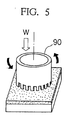
- flame spray coating plasma jet flame spray coating, gas flame spray coating and the like may be employed.
- the coating layer has the generated surface.
- the generated surface is machined and generated by the movable member during the operation of the relatively displacing apparatus.
- the oxide particles 51 are extremely hard, for instance, since the zirconium oxide has a hardness of Hv 1000 or more, it is believed that a large force is required to cause the shear fracture of the oxide particles 52 ("a-1" and "b-1").
- the coating layer includes the ceric oxide as well as the auxiliary powder for improving the machinabilitiy such as the BN powder, the graphite powder or the like
- the coating layer also has the structure as schematically illustrated in Figure 17.
- the auxiliary powder particles 52 are present on the boundaries of the oxide particles 51, i.e., the ceric oxide particles, in a laminated structure, and the pores 53 are also present on the boundaries of the oxide particles 51 and the auxiliary powder particles 52.
- the coating layer is thus machined easily without causing the damage to the movable member, thereby generating the generated layer. Since the clearance between the movable member and the stationary member is made zero (0) substantially by the generated surface, the gas leakage and the like has been prevented from happening and the efficiency of the displacing apparatus has been improved.
- the preferred embodiments are embodied in a turbocharger. They will be hereinafter described together with comparative examples manufactured in comparison therewith.
- the turbocharger of a second preferred embodiment was identical with that of the first preferred embodiment except that an abradable material was employed which included 65 % by volume of an aluminum oxide (Al2O3) powder and 35 % by volume of a BN powder.
- Al2O3 aluminum oxide
- BN powder was identical with the one employed in the first preferred embodiment.
- the turbocharger of comparative example 11 was basically identical with that of the first preferred embodiment except that the alloy layer 84 and the coating layer 85 were not formed on the portion "P" of the turbohousing 81.
- the turbocharger of comparative example 12 was identical with that of the first preferred embodiment except that an abradable material was employed which included a ZrO2 ⁇ 20Y2O3 powder.
- the ZrO2 ⁇ 20Y2O3 powder was produced by Showa Denko Co., Ltd., and had an average particle size of 10 to 44 ⁇ m.
- the coating layer had a porosity of 28 %.
- the turbocharger of comparative example 13 was identical with that of the first preferred embodiment except that an abradable material was employed which included 75 % by weight of nickel (Ni) powder and 25 % by weight of a graphite powder.
- the nickel powder had an average particle size of 10 to 74 ⁇ m
- the graphite powder had an average particle size of 10 to 30 ⁇ m and was produced by Perkin Elmer Co., Ltd.
- the turbochargers of the first and second preferred embodiment even in the case that the shaft 80 had an eccentricity and that the turborotor 82 was brought into contact with or collided with the turbohousing 81 during the operation, the coating layer 85 of the turbohousing 81 was easily machined by the turborotor 82, and a generated surface 851 was thereby generated on the coating layer 85 as illustrated in Figure 4. Accordingly, the turbochargers could prevent the turborotor 62 from being damaged.
- the turbochargers of the first and second preferred embodiment had the total efficiency improved by 5 to 6 % with respect to that of comparative example 11.
- the improvement is believed to result from the fact that the generated surface 851 made the clearance between the turbohousing 81 and the turborotor 82 zero (0) substantially as illustrated in Figure 4 and accordingly the gas leakage could be prevented to a minimum degree.
- the turbochargers of the first and third preferred embodiment did not show any faulty operation.
- the turbochargers of comparative examples 12, 13 and 14 generated chattering when the turborotors 82 were brought into contact with the turbohousings 81 in the operation because the coating layers were of inferior machinability.
- the coating layers of the turbochargers of comparative examples 12 and 13 were not machined, but they were come off when the turborotors 82 were brought into contact with the turbohousings 81 in the operation.
- the turbochargers of comparative examples 13 and 14 had corroded coating layers after the operation.
- the turbochargers of comparative examples 12, 13 and 14 had deformed turborotors 82 after the operation, and the turborotors 82 thereof exhibited the weight reductions due to wear.
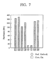
- Figure 7 illustrates the results of a hardness measurement on the hardnesses of the coating layers formed on the test pieces in accordance with the fourth and fifth preferred embodiment and comparative examples 15 through 20.
- the hardness measurement was carried out to obtain the Vickers hardness under a load of 5 kgf. It is apparent that the coating layers of the fourth and fifth preferred embodiment had extremely low Vickers hardnesses compared with those of the coating layers of comparative examples 15 through 20.
- the thermal shock resistance of the coating layer including the BN was evaluated by a thermal shock test, i.e., a thermal cycle test.
- a thermal shock test i.e., a thermal cycle test.
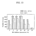
- the coating layers of the fourth and fifth preferred embodiment were formed on the test pieces in the same manner as aforementioned, however the addition amounts of the ZrO2 ⁇ 8Y2O3 and the Al2O3 were varied in a range of 50 to 100 % by volume and the addition amount of the BN was varied in a range of 0 to 50 % by volume.
- the test pieces thus prepared were subjected to a thermal cycle test.
- One cycle of the test consisted of a first step of heating the test pieces with an oxygen-acetylene burner to approximately 1000 °C in 32 seconds and a second step of quenching the test pieces by immersing them into water.
- the cycle was carried out repeatedly until part of or whole of the coating layers came off or fell off.
- the thermal shock resistance of the test pieces were rated by the number of the repeated cycles until the coming off or falling off. Here, checking was done every 50 cycles, and the cycle was repeated up to a maximum of 2000 times. The results of the test are illustrated in Figure 13.
- the coating layers of the fourth and fifth preferred embodiment were formed on the test pieces in the same manner as aforementioned, however the addition amounts of the ZrO2 ⁇ 8Y2O3 and the Al2O3 were varied in a range of 50 to 90 % by volume and the addition amount of the BN was varied in a range of 10 to 50 % by volume. Further, a coating layer was formed on test pieces in accordance with the United States Patent No. 4,269,903, and the coating layer included porous ZrO2 ⁇ 20Y2O3 and had a porosity of 20 to 33 %.
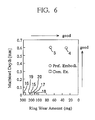
- the test pieces thus prepared were subjected to the machinability test described in section (1) above, and their machined depths (mm) and ring wear amounts (mg) were measured similarly. The results of the test are illustrated in Figure 14. In Figure 14, the machined depths and the ring wear amounts are plotted with respect to the same horizontal axis specifying the porosity of the coating layers of the test pieces in percentage.
- test pieces were subjected to the thermal shock test described in section (2)-(b) above, and their thermal shock resistances were evaluated similarly. The results of the test are illustrated in Figure 15.
- the coating layers including the BN exhibited better thermal shock resistances than the coating layers free from the BN in a porosity range of 20 to 33 %.
- the coating layers free from the BN exhibited increased machinability in a porosity range of over 40 % according to Figure 14, the thermal shock resistance deteriorated so sharply that the coating layers free from the BN were hardly applicable to a practical use as can be seen from Figure 15. Accordingly, the coating layers including the BN formed in accordance with the present invention were superior to the conventional porous coating layers in respect of the machinability and the thermal shock resistance.
- the coating layers of the fourth and fifth preferred embodiment were formed on the test pieces in the same manner as aforementioned, however the addition amounts of the ZrO2 ⁇ 8Y2O3 and the Al2O3 were set at 75 % by volume, and the addition amount of the BN was set at 25 % by volume. Further, a coating layer including nickel and graphite was formed on the test pieces. Furthermore, a coating layer including NiCrFeAl alloy and the BN was formed on the test pieces. Namely, the coating layer including nickel and graphite was formed of the abradable material according to comparative example 13, and the coating layer including NiCrFeAl alloy and the BN was formed of the abradable material according to comparative example 14.
- test pieces thus prepared were subjected to a corrosion resistance test.
- the corrosion resistance test was carried out in the following procedure: First, the test pieces were put in an oven whose temperature is held at 1000 °C. Then, the test pieces weighed from time to time to check their weight variations in mg, thereby evaluating their degrees of the oxidation. The results of the test are illustrated in Figure 16.
- the test pieces having the coating layers including the oxides and the BN showed no weight variation even at a high temperature of 1000 °C, and no failure resulting from the oxidation and the like occurred therein.
- the test pieces having the conventional nickel-base coating layers gained their weights as time passed because the oxidation developed therein. Accordingly, the coating layers including the BN formed in accordance with the present invention were much better than the conventional nickel-base coating layers in respect of the corrosion resistance.
- a turbocharger of a sixth preferred embodiment according to the present invention was manufactured in the same manner as the turbocharger of the first preferred embodiment except that a ceric oxide (CeO2) powder was employed for preparing an abradable material in the step (d) of the procedure for manufacturing the turbocharger.
- the ceric oxide powder had an average particle size of 10 to 74 ⁇ m and was Produced by Showa Denko Co., Ltd.
- the turbocharger of the sixth preferred embodiment thus manufactured had a coating layer 85 having a porosity of 23 %.
- the turbocharger of a seventh preferred embodiment was identical with that of the first preferred embodiment except that an abradable material was employed which included 75 % by volume of all ceric oxide powder and 25 % by volume of a ZrO2 ⁇ 20Y2O3 powder.
- the ZrO2 ⁇ 20Y2O3 powder (produced by Showa Denko Co., Ltd.) had an average particle size of 10 to 44 ⁇ m, and the ceric oxide powder was identical with the one employed in the sixth preferred embodiment.
- the turbocharger of the seventh preferred embodiment thus manufactured had a coating layer 85 having a porosity of 21 %.
- the turbocharger of an eighth preferred embodiment was identical with that of the first preferred embodiment except that an abradable material was employed which included 30 % by volume of a ceric oxide powder and 70 % by volume of a ZrO2 ⁇ 20Y2O3 powder.
- the ZrO2 ⁇ 20Y2O3 powder was identical with the one employed in the seventh preferred embodiment, and the ceric oxide is the one employed in the sixth preferred embodiment.
- the turbocharger of the eighth preferred embodiment thus manufactured had a coating layer 85 having a porosity of 19 %.
- the turbocharger of comparative example 21 was identical with that of the first preferred embodiment except that an abradable material was employed which included 100 % by volume of ZrO2 ⁇ 20Y2O3 powder.
- the ZrO2 ⁇ 20Y2O3 powder was identical with the one employed in the seventh preferred embodiment.
- the turbocharger of the comparative example 21 thus manufactured had a coating layer having a porosity of 30 %.
- the turbocharger of comparative example 22 was identical with that of the first preferred embodiment except that an abradable material was employed which included 100 % by volume of an Al2O3 powder.
- the Al2O3 powder was Produced by Metco Co., Ltd., and had an average particle size of 35 to 74 ⁇ m.
- the turbocharger of the comparative example 22 thus manufactured had a coating layer having a porosity of 28 %.
- turbochargers of the sixth, seventh and eighth preferred embodiment as well as comparative example 21 and 22 were subjected to the above-mentioned 300-hour durability test simulating an actual operation for evaluating the noise during the 300 hour-operation, the coating layer state after the operation and the turborotor state after the operation.
- the weight reductions (in grams) of the turborotors 82 were also measured after the operation.
- the results of the tests are set forth in Table 5.
- the turbochargers were rated in a "Total Evaluation" column of Table 5 with either a "Good” sign identifying an excellent turbocharger and a "Bad” sign identifying an inferior turbocharger. Table 5 Turbocharger Noise during Oper.
- the turbochargers of the sixth and seventh preferred embodiment did not show any faulty operation such as chattering, coming off or falling off of the coating layer 85, damaged turborotor 82, because the coating layer 85 of the turbohousing 81 was easily machined by the turborotor 82 and the generated surface 851 is thereby generated on the coating layer 85 as illustrated in Figure 4 even in the case that the turborotor 82 was brought into contact with or collided with the turbohousing 81 during the operation. Additionally, the turbocharger of the eighth preferred embodiment showed any particular problem other than that it generated a bit of low chattering.
- the turbochargers of comparative examples 21 and 22 generated loud chattering when the turborotors 82 were brought into contact with the turbohousings 81 in the operation because the coating layers were of inferior machinability.
- the coating layer of the turbocharger of comparative example 21 was not machined, but it was come off when the turborotor 82 was brought into contact with the turbohousing 81 in the operation.
- the turbocharger of comparative example 21 had the deformed blades of the turborotor 82, and showed a weight reduction due to wear after the operation.
- turbocharger of comparative example 22 one third of the coating layer come off because of the poor thermal shock resistance at 950 °C, i.e., the maximum temperature to which the turbochargers were applied.
- the blades of the turborotor 82 were deformed and cracked. The deformed and cracked blades are believed to result from the poor machinability of the coating layer and the collisions of the fragments of the come-off coating layer.
- the turbocharger of comparative example 22 accordingly showed the largest weight reduction or wear amount of 12 grams.
- the turbochargers of the sixth and seventh preferred embodiment were also subjected to the product performance test for evaluating the total efficiency (%) under the condition of the rotor speed of a hundred thousand rpm.
- the turbochargers of the sixth and seventh preferred embodiment had the total efficiency improved by 5.3 and 5.1 % respectively with respect to the turbocharger without the coating layer which had the total efficiency of 51 %. It is believed that the generated surface 851 made the clearance between the turbohousing 81 and the turborotor 82 zero (0) substantially as illustrated in Figure 4 and accordingly the gas leakage could be suppressed to a minimum degree, thereby making the improvement possible.
- the turborotors 82 could be prevented from being damaged, and the efficiency of the turbochargers could be improved.
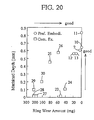
- Abradable materials were prepared whose compositions are set forth in Table 6. Then, coating layers were formed of the abradable materials of the ninth through thirteenth preferred embodiment as well as comparative examples 23 through 30 in the same manner as described in section (1) of Fourth and Fifth Preferred Embodiment.
- the BN powder ("UHP-EX" produced by Showa Denko Co., Ltd.) had an average particle size of 35 to 45 ⁇ m
- the CeO2 powder, the Al3O3 powder and the ZrO2 ⁇ 20Y2O3 powder were identical with those employed by the sixth through seventh preferred embodiment or the comparative examples 21 and 22.
- test pieces thus prepared were subjected to the machinability test for comparing their machinabilities described in section (1) of Fourth and Fifth Preferred Embodiment.
- the results of the machinability test are illustrated in Figure 20.
- the coating layers of the comparative examples 23 and 24 are compared with the coating layers of the comparative examples 25 and 26, the machinabilites of the ZrO2 ⁇ 20Y2O3-base coating layers were improved by adding the BN.
- these coating layers had slightly strong mating part attacking tendencies or slightly large ring wear amounts, they were a bit inadequate for an abradable material for adjusting the clearance in a relatively displacing apparatus.
- the CeO2-base coating layers of the ninth through thirteenth preferred embodiment could have weak mating part attacking tendencies and excellent machinabilities even when the auxiliary powder such as the BN and the like was not added therein.
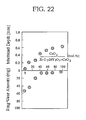
- the coating layer formed by flame spray coating the ceric oxide had a favorable machinability, an optimum ceric oxide addition amount was evaluated in view of the machinability and the thermal shock resistance.
- the coating layers of the thirteenth preferred embodiment were formed on the test pieces in the same manner as aforementioned, however the addition amounts of the ceric oxide and the ZrO2 ⁇ 20Y2O3 were vaired variously in a range of 0 to 100 % by volume.
- the ZrO2 ⁇ 20Y2O3 and the ceric oxide were identical with the above-mentioned ones.
- the test pieces thus prepared were subjected to the machinability test described in section (1) of Fourth and Fifth Preferred, and their machined depths (mm) and ring wear amounts (mg) were measured similarly. The results of the test are illustrated in Figure 22.
- the coating layer came to have more favorable machinability as the ceric oxide was added more in the abradable material.
- the machinability i.e., the machined depth of the coating layer
- the coating layer of the comparative example 24 was formed in accordance with the United States Patent No. 4,269,903. Further, when the ceric oxide was added by less than 10 % by volume, the machinability of the coating layer decreased sharply. Consequently, it is necessary to include the ceric oxide by 10 % by volume or more in order to obtain a coating layer of a favorable machinability.
- the thermal shock resistance of the coating layer including the ceric oxide was evaluated by the thermal shock test described in section (2)-(b) of Fourth and Fifth Preferred Embodiment.
- the coating layers of the twelfth and thirteenth preferred embodiment were formed on the test pieces in the same manner as aforementioned, however, in the coating layers of this thirteenth preferred embodiment, ZrO2 ⁇ 8Y2O3 was used instead of the ZrO2 ⁇ 20Y2O3, and the addition amount of the ceric oxide with respect to the ZrO2 ⁇ 8Y2O3 or the Al2O3 was varied variously in a range of 0 to 100 % by volume. Further, comparative test pieces were prepared on which the abradable materials of the comparative examples 24 and 27 were coated by Plasma jet flame spray coating.
- the alloy including the NiCrAl alloy was coated by plasma jet flame spray coating in a thickness of 1 mm before flame coating the abradable materials.
- the ZrO2 ⁇ 8Y2O3 powder ("K90" produced by Showa Denko Co., Ltd.) had an average particle size of 10 to 74 ⁇ m, and the Al2O3 and the ceric oxide were identical with the above-mentioned ones.
- the test pieces thus prepared were subjected to the thermal cycle test. The results of the test are illustrated in Figure 23.
- the thermal shock resistances of the coating layers of the preferred embodiments were substantially equivalent to those of the comparative examples 24 and 27.
- the thermal shock resistances of the coating layers of the preferred embodiments improved to equivalent to or more than those of the coating layers of the comparative examples 24 and 27.
- the ZrO2 ⁇ 8Y2O3 was superior to the Al2O3 as the oxide to be included in the coating layer in respect of the thermal shock resistance.
Landscapes
- Engineering & Computer Science (AREA)
- Mechanical Engineering (AREA)
- General Engineering & Computer Science (AREA)
- Supercharger (AREA)
- Other Surface Treatments For Metallic Materials (AREA)
- Coating By Spraying Or Casting (AREA)
Applications Claiming Priority (4)
| Application Number | Priority Date | Filing Date | Title |
|---|---|---|---|
| JP233845/89 | 1989-09-08 | ||
| JP23384589A JPH0396601A (ja) | 1989-09-08 | 1989-09-08 | 相対移動装置 |
| JP293077/89 | 1989-11-10 | ||
| JP29307789A JPH03156103A (ja) | 1989-11-10 | 1989-11-10 | 相対移動装置 |
Publications (2)
| Publication Number | Publication Date |
|---|---|
| EP0416954A1 true EP0416954A1 (fr) | 1991-03-13 |
| EP0416954B1 EP0416954B1 (fr) | 1994-06-22 |
Family
ID=26531228
Family Applications (1)
| Application Number | Title | Priority Date | Filing Date |
|---|---|---|---|
| EP90309851A Expired - Lifetime EP0416954B1 (fr) | 1989-09-08 | 1990-09-07 | Matériau s'usant pour turbo machine |
Country Status (3)
| Country | Link |
|---|---|
| US (1) | US5185217A (fr) |
| EP (1) | EP0416954B1 (fr) |
| DE (1) | DE69010122T2 (fr) |
Cited By (5)
| Publication number | Priority date | Publication date | Assignee | Title |
|---|---|---|---|---|
| DE10010117B4 (de) * | 1999-03-04 | 2004-03-25 | Cummins Inc., Columbus | Beschichtete Kompressorleiteinrichtung |
| WO2005038199A1 (fr) * | 2003-10-13 | 2005-04-28 | Daimlerchrysler Ag | Turbomachine et procede pour adapter le stator et le rotor d'une turbomachine |
| EP1658925A1 (fr) * | 2004-11-20 | 2006-05-24 | Borgwarner, Inc. | Procédé de fabrication pour un carter de compresseur |
| EP1914329A1 (fr) * | 2006-10-16 | 2008-04-23 | Siemens Aktiengesellschaft | Dispositif et procédé pour augmenter la durée de fonctionnement d'un dispositif de combustion |
| EP2578804A1 (fr) * | 2011-09-20 | 2013-04-10 | United Technologies Corporation | Joint d'usure léger, moteur à turbine à gaz et procédé de fabrication associés |
Families Citing this family (21)
| Publication number | Priority date | Publication date | Assignee | Title |
|---|---|---|---|---|
| RU2115812C1 (ru) * | 1994-02-16 | 1998-07-20 | Юнайтед Технолоджиз Корпорейшн | Способ и устройство удержания расплавленного материала в процессе горения в газотурбинном двигателе (варианты) |
| GB9520497D0 (en) * | 1995-10-07 | 1995-12-13 | Holset Engineering Co | Improvements in turbines and compressors |
| JP3294491B2 (ja) * | 1995-12-20 | 2002-06-24 | 株式会社日立製作所 | 内燃機関の過給機 |
| JPH1088368A (ja) * | 1996-09-19 | 1998-04-07 | Toshiba Corp | 遮熱コーティング部材およびその作製方法 |
| FR2840839B1 (fr) * | 2002-06-14 | 2005-01-14 | Snecma Moteurs | Materiau metallique susceptible d'etre use par abrasion; pieces, carter; procede d'elaboration dudit materiau |
| US20040109760A1 (en) * | 2002-12-04 | 2004-06-10 | Jones Daniel W. | Method and apparatus for increasing the adiabatic efficiency of a centrifugal compressor |
| DE102004042258B3 (de) * | 2004-08-30 | 2006-01-19 | Daimlerchrysler Ag | Verfahren zur Herstellung eines Konturspalts sowie Strömungsmaschine mit einem Konturspalt |
| DE102004042127B4 (de) * | 2004-08-30 | 2006-07-13 | Daimlerchrysler Ag | Rotor-Stator-Vorrichtung mit Anstreifbelag, Verfahren zu deren Herstellung sowie Verwendung |
| DE112005002258T5 (de) * | 2004-09-20 | 2007-08-02 | Metaldyne Co. LLC, Plymouth | Laufrad mit abriebfähiger Spitze |
| WO2006038328A1 (fr) * | 2004-09-30 | 2006-04-13 | Eagle Engineering Aerospace Co., Ltd. | Joint d’étanchéité |
| US20100015350A1 (en) * | 2008-07-16 | 2010-01-21 | Siemens Power Generation, Inc. | Process of producing an abradable thermal barrier coating with solid lubricant |
| DE102009031787A1 (de) | 2009-07-06 | 2011-01-13 | Volkswagen Ag | Abgasturbolader mit einer Radialturbine |
| US20110027573A1 (en) * | 2009-08-03 | 2011-02-03 | United Technologies Corporation | Lubricated Abradable Coating |
| CA2713316C (fr) * | 2009-08-17 | 2017-09-26 | Pratt & Whitney Canada Corp. | Architecture de section de turbine a gaz |
| DE102009055914A1 (de) * | 2009-11-27 | 2011-06-09 | Rolls-Royce Deutschland Ltd & Co Kg | Dichtringe für eine Labyrinthdichtung |
| WO2015053948A1 (fr) * | 2013-10-09 | 2015-04-16 | United Technologies Corporation | Revêtement en alliage d'aluminium dotés d'inhibiteurs de corrosion de type terres rares et métaux de transition |
| US9850778B2 (en) | 2013-11-18 | 2017-12-26 | Siemens Energy, Inc. | Thermal barrier coating with controlled defect architecture |
| WO2016135973A1 (fr) * | 2015-02-27 | 2016-09-01 | 三菱重工業株式会社 | Procédé de fabrication d'un turbocompresseur |
| DE102016209951A1 (de) * | 2016-06-07 | 2017-12-07 | Ford Global Technologies, Llc | Zusammengesetztes Turbinengehäuse |
| DE202017103440U1 (de) * | 2017-06-08 | 2018-09-11 | Borgwarner Inc. | Einsatz für einen Verdichter |
| EP3940203A1 (fr) | 2020-07-16 | 2022-01-19 | BMTS Technology GmbH & Co. KG | Turbine de gaz d'échappement |
Citations (8)
| Publication number | Priority date | Publication date | Assignee | Title |
|---|---|---|---|---|
| US3053694A (en) * | 1961-02-20 | 1962-09-11 | Gen Electric | Abradable material |
| US3084064A (en) * | 1959-08-06 | 1963-04-02 | Union Carbide Corp | Abradable metal coatings and process therefor |
| US3879831A (en) * | 1971-11-15 | 1975-04-29 | United Aircraft Corp | Nickle base high temperature abradable material |
| FR2256125A1 (fr) * | 1973-12-26 | 1975-07-25 | Union Carbide Corp | |
| GB1528421A (en) * | 1975-09-22 | 1978-10-11 | Nissan Motor | Shroud for rotor or impeller of a turbine or compressor with abradable seal layer on inside to establish minimized running clearance |
| FR2436882A1 (fr) * | 1978-09-22 | 1980-04-18 | Gen Electric | Element d'etancheite pour virole de turbine a gaz |
| EP0166097A1 (fr) * | 1984-05-02 | 1986-01-02 | The Perkin-Elmer Corporation | Poudre d'oxyde de zirconium contenant l'oxyde de cérium et l'oxyde d'yttrium |
| EP0187612A2 (fr) * | 1984-12-24 | 1986-07-16 | United Technologies Corporation | Joint d'étanchéité abrasable ayant une résistance élevée à l'érosion |
Family Cites Families (8)
| Publication number | Priority date | Publication date | Assignee | Title |
|---|---|---|---|---|
| NL260152A (fr) * | 1960-01-18 | |||
| DE2217536C2 (de) * | 1972-04-12 | 1974-05-09 | Carl Schenck Maschinenfabrik Gmbh, 6100 Darmstadt | Anordnung zur Regelung einer dynamischen Prüfanlage, insbesondere für eine hydraulisch angetriebene |
| AT324541B (de) * | 1973-03-16 | 1975-09-10 | Bock Orthopaed Ind | Vorrichtung zum lösbaren verbinden eines arbeitsgerätes mit einem armprothesenschaft |
| US4269903A (en) * | 1979-09-06 | 1981-05-26 | General Motors Corporation | Abradable ceramic seal and method of making same |
| DE3018620C2 (de) * | 1980-05-16 | 1982-08-26 | MTU Motoren- und Turbinen-Union München GmbH, 8000 München | Wärmedämmende und dichtende Auskleidung für eine thermische Turbomaschine |
| US4328285A (en) * | 1980-07-21 | 1982-05-04 | General Electric Company | Method of coating a superalloy substrate, coating compositions, and composites obtained therefrom |
| JPS62168926A (ja) * | 1986-01-20 | 1987-07-25 | Nissan Motor Co Ltd | タ−ボチヤ−ジヤ |
| JPH0267160A (ja) * | 1988-09-02 | 1990-03-07 | Seiko Epson Corp | 画像読み取り装置 |
-
1990
- 1990-09-07 EP EP90309851A patent/EP0416954B1/fr not_active Expired - Lifetime
- 1990-09-07 US US07/578,650 patent/US5185217A/en not_active Expired - Lifetime
- 1990-09-07 DE DE69010122T patent/DE69010122T2/de not_active Expired - Fee Related
Patent Citations (8)
| Publication number | Priority date | Publication date | Assignee | Title |
|---|---|---|---|---|
| US3084064A (en) * | 1959-08-06 | 1963-04-02 | Union Carbide Corp | Abradable metal coatings and process therefor |
| US3053694A (en) * | 1961-02-20 | 1962-09-11 | Gen Electric | Abradable material |
| US3879831A (en) * | 1971-11-15 | 1975-04-29 | United Aircraft Corp | Nickle base high temperature abradable material |
| FR2256125A1 (fr) * | 1973-12-26 | 1975-07-25 | Union Carbide Corp | |
| GB1528421A (en) * | 1975-09-22 | 1978-10-11 | Nissan Motor | Shroud for rotor or impeller of a turbine or compressor with abradable seal layer on inside to establish minimized running clearance |
| FR2436882A1 (fr) * | 1978-09-22 | 1980-04-18 | Gen Electric | Element d'etancheite pour virole de turbine a gaz |
| EP0166097A1 (fr) * | 1984-05-02 | 1986-01-02 | The Perkin-Elmer Corporation | Poudre d'oxyde de zirconium contenant l'oxyde de cérium et l'oxyde d'yttrium |
| EP0187612A2 (fr) * | 1984-12-24 | 1986-07-16 | United Technologies Corporation | Joint d'étanchéité abrasable ayant une résistance élevée à l'érosion |
Non-Patent Citations (2)
| Title |
|---|
| JOURNAL OF AIRCRAFT. vol. 16, no. 4, April 1979, NEW YORK US pages 239 - 246; Taylor+Bill: "Thermal Stresses in a Plasma-Sprayed Ceramic Gas Path Seal" * |
| PATENT ABSTRACTS OF JAPAN vol. 13, no. 380 (M-863)(3728) 23 August 1989, & JP-A-01 134004 (TADASHI) 26 May 1989, * |
Cited By (10)
| Publication number | Priority date | Publication date | Assignee | Title |
|---|---|---|---|---|
| DE10010117B4 (de) * | 1999-03-04 | 2004-03-25 | Cummins Inc., Columbus | Beschichtete Kompressorleiteinrichtung |
| WO2005038199A1 (fr) * | 2003-10-13 | 2005-04-28 | Daimlerchrysler Ag | Turbomachine et procede pour adapter le stator et le rotor d'une turbomachine |
| US7850416B2 (en) | 2003-10-13 | 2010-12-14 | Daimler Ag | Turboengine and method for adjusting the stator and rotor of a turboengine |
| EP1658925A1 (fr) * | 2004-11-20 | 2006-05-24 | Borgwarner, Inc. | Procédé de fabrication pour un carter de compresseur |
| EP1914329A1 (fr) * | 2006-10-16 | 2008-04-23 | Siemens Aktiengesellschaft | Dispositif et procédé pour augmenter la durée de fonctionnement d'un dispositif de combustion |
| WO2008046747A1 (fr) * | 2006-10-16 | 2008-04-24 | Siemens Aktiengesellschaft | Dispositif et procédé d'augmentation de la durée de vie d'installations de combustion |
| AU2007312379B2 (en) * | 2006-10-16 | 2011-07-28 | Siemens Aktiengesellschaft | Device and method for increasing the service life of combustion installations |
| CN101528980B (zh) * | 2006-10-16 | 2012-07-18 | 西门子公司 | 用于提高燃烧设备的运行寿命的装置和方法 |
| US8356621B2 (en) | 2006-10-16 | 2013-01-22 | Siemens Aktiengesellschaft | Device and method for extending the service life of firing installations |
| EP2578804A1 (fr) * | 2011-09-20 | 2013-04-10 | United Technologies Corporation | Joint d'usure léger, moteur à turbine à gaz et procédé de fabrication associés |
Also Published As
| Publication number | Publication date |
|---|---|
| US5185217A (en) | 1993-02-09 |
| EP0416954B1 (fr) | 1994-06-22 |
| DE69010122T2 (de) | 1994-11-17 |
| DE69010122D1 (de) | 1994-07-28 |
Similar Documents
| Publication | Publication Date | Title |
|---|---|---|
| US5185217A (en) | Relatively displacing apparatus | |
| EP0340791A2 (fr) | Pièce en alliage réfractaire revêtue de céramique | |
| EP0944767B1 (fr) | Procédé de fabrication d'un joint abradable, joint abradable, et composant de moteur à turbine à gaz pourvu d'un tel joint abradable | |
| US5384200A (en) | Thermal barrier coating and method of depositing the same on combustion chamber component surfaces | |
| US4289446A (en) | Ceramic faced outer air seal for gas turbine engines | |
| Bill et al. | Wear of seal materials used in aircraft propulsion systems | |
| CN1457384A (zh) | 内燃机、燃气轮机和研磨层 | |
| US5682596A (en) | High temperature anti-fretting wear coating combination | |
| JPS59205466A (ja) | 耐摩耗性被覆層 | |
| US6916551B2 (en) | Thermal barrier coating material, gas turbine parts and gas turbine | |
| EP0961017B1 (fr) | Revêtement de protection résistant aux températures élevées | |
| EP0225781B1 (fr) | Fritte céramique ayant un haut coefficient de dilatation thermique et un corps composite du même matériau et du métal | |
| US7165946B2 (en) | Low-mid turbine temperature abradable coating | |
| US6423432B1 (en) | High temperature corrosion-resistant and abrasion-resistant coating member, and manufacturing method thereof | |
| Sporer et al. | On The Potential Of Metal And Ceramic Based Abradables In Turbine Seal Applications. | |
| EP1338670B1 (fr) | Revêtement abradable et procédé de préparation | |
| US5082741A (en) | Thermal spray material and thermal sprayed member using the same | |
| US20240059904A1 (en) | Composite thermal spray powder of oxides and non-oxides | |
| JP2823086B2 (ja) | 連結部材およびその連結方法 | |
| Matoba et al. | The Development of Second Generation Ceramic Turbocharger Rotor-Further Improvements in Reliability | |
| Chupp et al. | Development of higher temperature abradable seals for gas turbine applications | |
| JPH03156103A (ja) | 相対移動装置 | |
| US5032557A (en) | Thermal spray material and and thermal sprayed member using the same | |
| JPH08246901A (ja) | 耐酸化性に優れた遮熱コーティング膜 | |
| JPH0396601A (ja) | 相対移動装置 |
Legal Events
| Date | Code | Title | Description |
|---|---|---|---|
| PUAI | Public reference made under article 153(3) epc to a published international application that has entered the european phase |
Free format text: ORIGINAL CODE: 0009012 |
|
| 17P | Request for examination filed |
Effective date: 19900914 |
|
| AK | Designated contracting states |
Kind code of ref document: A1 Designated state(s): DE FR GB |
|
| 17Q | First examination report despatched |
Effective date: 19921029 |
|
| GRAA | (expected) grant |
Free format text: ORIGINAL CODE: 0009210 |
|
| AK | Designated contracting states |
Kind code of ref document: B1 Designated state(s): DE FR GB |
|
| REF | Corresponds to: |
Ref document number: 69010122 Country of ref document: DE Date of ref document: 19940728 |
|
| ET | Fr: translation filed | ||
| PLBE | No opposition filed within time limit |
Free format text: ORIGINAL CODE: 0009261 |
|
| STAA | Information on the status of an ep patent application or granted ep patent |
Free format text: STATUS: NO OPPOSITION FILED WITHIN TIME LIMIT |
|
| 26N | No opposition filed | ||
| PGFP | Annual fee paid to national office [announced via postgrant information from national office to epo] |
Ref country code: GB Payment date: 19970829 Year of fee payment: 8 |
|
| PGFP | Annual fee paid to national office [announced via postgrant information from national office to epo] |
Ref country code: FR Payment date: 19970909 Year of fee payment: 8 |
|
| PGFP | Annual fee paid to national office [announced via postgrant information from national office to epo] |
Ref country code: DE Payment date: 19970912 Year of fee payment: 8 |
|
| PG25 | Lapsed in a contracting state [announced via postgrant information from national office to epo] |
Ref country code: GB Free format text: LAPSE BECAUSE OF NON-PAYMENT OF DUE FEES Effective date: 19980907 |
|
| GBPC | Gb: european patent ceased through non-payment of renewal fee |
Effective date: 19980907 |
|
| PG25 | Lapsed in a contracting state [announced via postgrant information from national office to epo] |
Ref country code: FR Free format text: LAPSE BECAUSE OF NON-PAYMENT OF DUE FEES Effective date: 19990531 |
|
| PG25 | Lapsed in a contracting state [announced via postgrant information from national office to epo] |
Ref country code: DE Free format text: LAPSE BECAUSE OF NON-PAYMENT OF DUE FEES Effective date: 19990701 |
|
| REG | Reference to a national code |
Ref country code: FR Ref legal event code: ST |