EP0415467B1 - Control apparatus - Google Patents
Control apparatus Download PDFInfo
- Publication number
- EP0415467B1 EP0415467B1 EP90202037A EP90202037A EP0415467B1 EP 0415467 B1 EP0415467 B1 EP 0415467B1 EP 90202037 A EP90202037 A EP 90202037A EP 90202037 A EP90202037 A EP 90202037A EP 0415467 B1 EP0415467 B1 EP 0415467B1
- Authority
- EP
- European Patent Office
- Prior art keywords
- control member
- shaft
- counterweight
- shafts
- control
- Prior art date
- Legal status (The legal status is an assumption and is not a legal conclusion. Google has not performed a legal analysis and makes no representation as to the accuracy of the status listed.)
- Expired - Lifetime
Links
Images

Classifications
-
- B—PERFORMING OPERATIONS; TRANSPORTING
- B64—AIRCRAFT; AVIATION; COSMONAUTICS
- B64D—EQUIPMENT FOR FITTING IN OR TO AIRCRAFT; FLIGHT SUITS; PARACHUTES; ARRANGEMENTS OR MOUNTING OF POWER PLANTS OR PROPULSION TRANSMISSIONS IN AIRCRAFT
- B64D31/00—Power plant control; Arrangement thereof
- B64D31/02—Initiating means
- B64D31/04—Initiating means actuated personally
Definitions
- This invention relates to control apparatus, and in particular to apparatus for controlling an aircraft engine throttle (such apparatus being known as a "throttle box").
- a throttle box in which a control member is linearly movable upon a shaft to generate a control output signal to control the engine throttle opening. This movement may be effected either manually by a pilot or automatically when the aircraft is under the control of an autopilot.
- a throttle box is known, for example, from GB-A-2073887. Problems may occur, however, with such a throttle box when the aircraft experiences high g-forces. Forces of up to 10g, which may be experienced for example when manoeuvring at high speeds, may cause the control member to move and produce an unwanted change in the throttle opening. Alternatively high g-forces may make it difficult for the pilot to move the control member if he does desire to change the throttle opening.
- Conventionally such a throttle box is disposed in the cockpit adjacent the pilot and arranged such that the control member moves in a fore-aft direction. Thus the throttle box is particularly susceptible to fore-aft acceleration forces.
- a control apparatus comprising a control member linearly movable on a first shaft, and means for detecting the position of said control member relative to said first shaft and generating an output control signal in response thereto, and further comprising a second shaft parallel to said first shaft and having linearly movable thereon a counterweight, said shafts being coupled and driven together such that movement of said control member causes said counterweight to move with, but in the opposite direction to, said control member.
- control member and the counterweight are both threadably mounted on their respective shafts through ball screws, and said shafts are able to rotate in synchronism, but in opposite senses, by drive gearing.
- the shafts in an autopilot mode the shafts may be driven by a motor through said gearing to move the control member to give the pilot a visual indication of the throttle opening selected by the autopilot.
- the pilot In a manual mode the pilot may move the control member and cause the two shafts to rotate.
- the position of the control member on its shaft represents engine throttle demand and may be detected by means measuring the amount of rotation of one or other of the shafts with respect to a datum. Such rotation may be detected to produce an output signal to an engine control unit.
- the counterweight may also be employed to operate additional control means, for example a microswitch, by its movement so that, say, the engine may not be started until the control member has moved to a given position.
- additional control means for example a microswitch
- a locking mechanism may be provided to lock the control member in a 'throttle off' position when desired.
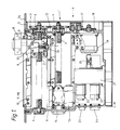
- the overall form of the throttle box is that of a box generally square when viewed side on, but relatively short in a direction normal to Figure 1.
- the throttle box 1 includes first and second threaded shafts 2, 3 rotatably mounted in bearings 4 formed in end walls 5, 6 of the box 1.
- the threads of the shafts 2 and 3 are identical in size, sense and pitch.
- the first shaft 2 carries, through a trunnion mounted ball nut 7, a control member 8 which is guided for linear movement along shaft 2 by four wheels 9 rotatably fitted to the control member 8 and running along tracks 10 bolted to the interior side wall of the throttle box.
- the throttle box is located within the aircraft cockpit adjacent the pilots seat and such that the shafts 2 and 3 are substantially parallel to the fore and aft axis of the aircraft.
- the control member 8 includes a handle (not shown) by means of which the control member may be moved along the shaft 2 by a pilot. It will be appreciated that by virtue of the threaded mounting of the control member 8 on shaft 2, as the control member is moved linearly the shaft 2 is caused to rotate in bearings 4. This rotation of shaft 2 is transmitted to a parallel second shaft 3 below through meshing identical gears 11, 12 fixed to the ends of the two shafts 2, 3.
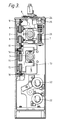
- the second shaft 3 carries thereon a counterweight 13 of substantially identical weight to the control member 8.
- the counterweight is mounted through a similar ball nut 14 as the control member 8, and is guided for linear movement by a similar wheel 15 and track 16 arrangement (See Figure 3). Since gears 11, 12, formed on the ends of shafts 2, 3 respectively, directly mesh with one another the two shafts will always rotate in opposite directions to one another, and since the thread on the two shafts is of the same sense, this means that the control member 8 and counterweight 13 will always move in linearly opposite directions, as will be discussed further below.
- the gears 11, 12 are linked, via an intermediate idler gear 17, to a further gear 18 provided at the end of an output shaft of a torque motor 19.
- the motor 19 is in turn linked by a flexible coupling 20 to a gear-box 21 and a pair of potentiometers 22 (providing a duplex electrical system) which produce output signals via output pins on sockets 23.
- the ball screw assemblies 7, 14 are of a short length type as described in our co-pending application.
- a pilot moves the control member 8 linearly to a desired position corresponding to a particular engine throttle setting.
- This linear motion of control member 8 causes rotation of shaft 2, and, through gearing 11, 12, 17, 18, rotation of shaft 3 and stepper motor 19.
- the rotation of the stepper motor 19 drives the gearbox 21 and potentiometers 22, to produce two output signals that are dependant on the position of the control member 8, and control the engine throttle opening by an electro mechanical servo system (not shown).
- the counterweight 13 moves with the control member 8, but in the opposite direction, to balance the movement of the control member. For example, if the control member is urged by an acceleration force in a first direction, by means of the coupling between the two shafts the counterweight will be urged in the opposite direction. However, the counterweight itself will also be urged in the first direction by the acceleration force to resist movement of the counterweight and thus of the linked control member.
- the throttle box When an aircraft is being flown in an autopilot mode, the throttle box will receive, as an input to the torque motor, an electrical demand signal dependant on the throttle opening selected by an autopilot. Such an input signal causes the stepper motor to rotate an amount dependant on the throttle opening demanded and such rotation of the torque motor will, through gearing 11, 12, 17, 18 cause shafts 2, 3 to rotate and, in particular, the control member 8 to move linearly.
- the control member 8 will be moved automatically by the autopilot system to indicate to the pilot the throttle opening selected by the autopilot. Again, movement of the torque motor will cause rotation of the potentiometers and hence the transmission of demand signals to the electro-mechanical engine throttle servo mechanism.
- the torque motor may also be employed if desired, to provide an artificial 'feel' or resistance to movement of the control member 8.
- the stepper motor 19 may be energised in such a sense as to urge the control member 8 in the opposite direction, though only of course to an extent that can be overcome by the pilot.
- the torque motor 19 may be energised to resist movement of the control member 8 at selected points along shaft 2. In this way an electrical detent system may be provided to indicate to the pilot when the control member 8 passes selected points on shaft 2.
- a mechanical detent system may be provided as shown in the embodiment of the Figures.
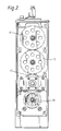
- the top wall 24 of the throttle box may be provided with a track parallel to the shaft 2 and having cam regions at selected points therealong. Engaging this track is a cam follower 25 fixed to the side of the control member 8 and biassed into engagement with the track by a spring 26. When the cam follower 25 engages the cam regions of the track a degree of resistance will be felt by the pilot.
- FIG 4 shows a detail of the throttle box that is left out of Figure 1 for clarity.
- a latching mechanism that may be used to lock the control member 8 in a "throttle off" position.
- This mechanism comprises a latch member 27 that is downwardly biassed by spring 28 but which may be raised by pulling upwardly the head 29 of shaft 30 to which the latch member 27 is attached.
- the latch member 27 is adapted to engage a corresponding recess (not shown) formed on the control member.
- the counterweight 13 may also be used to sense the position of the control member.
- a microswitch is provided that is operated by the counterweight 13 when it reaches the end of shaft 3 remote from the latching mechanism; that is to say the microswitch is operated when the control member 8 reaches its throttle closed position.
- This microswitch may be used in circuits to ensure that various functions cannot or can only (as the case may be) operate when the throttle is closed and the engine shut down.
Description
- This invention relates to control apparatus, and in particular to apparatus for controlling an aircraft engine throttle (such apparatus being known as a "throttle box").
- A throttle box is known in which a control member is linearly movable upon a shaft to generate a control output signal to control the engine throttle opening. This movement may be effected either manually by a pilot or automatically when the aircraft is under the control of an autopilot. Such a throttle box is known, for example, from GB-A-2073887. Problems may occur, however, with such a throttle box when the aircraft experiences high g-forces. Forces of up to 10g, which may be experienced for example when manoeuvring at high speeds, may cause the control member to move and produce an unwanted change in the throttle opening. Alternatively high g-forces may make it difficult for the pilot to move the control member if he does desire to change the throttle opening. Conventionally such a throttle box is disposed in the cockpit adjacent the pilot and arranged such that the control member moves in a fore-aft direction. Thus the throttle box is particularly susceptible to fore-aft acceleration forces.
- According to the present invention there is provided a control apparatus comprising a control member linearly movable on a first shaft, and means for detecting the position of said control member relative to said first shaft and generating an output control signal in response thereto, and further comprising a second shaft parallel to said first shaft and having linearly movable thereon a counterweight, said shafts being coupled and driven together such that movement of said control member causes said counterweight to move with, but in the opposite direction to, said control member.
- By means of this arrangement the above mentioned problems are overcome, or at least mitigated, by the provision of the balancing counterweight.
- In a preferred embodiment the control member and the counterweight are both threadably mounted on their respective shafts through ball screws, and said shafts are able to rotate in synchronism, but in opposite senses, by drive gearing. In such an embodiment, in an autopilot mode the shafts may be driven by a motor through said gearing to move the control member to give the pilot a visual indication of the throttle opening selected by the autopilot. In a manual mode the pilot may move the control member and cause the two shafts to rotate. The position of the control member on its shaft represents engine throttle demand and may be detected by means measuring the amount of rotation of one or other of the shafts with respect to a datum. Such rotation may be detected to produce an output signal to an engine control unit.
- In a preferred arrangement the counterweight may also be employed to operate additional control means, for example a microswitch, by its movement so that, say, the engine may not be started until the control member has moved to a given position. In addition a locking mechanism may be provided to lock the control member in a 'throttle off' position when desired.
- An embodiment of the invention will now be described by way of example and with reference to the accompanying drawings, in which:-
- Figure 1 is a section through a throttle box viewed from one side,
- Figure 2 is an end view of the throttle box in the direction of arrow A, of Figure 1,
- Figure 3 is a section along line C-C of Figure 1, and
- Figure 4 is an enlarged detail of a locking mechanism of the throttle box of Figure 1.
- Referring firstly to Figure 1 there is shown a throttle box designated generally by reference numeral 1. The overall form of the throttle box is that of a box generally square when viewed side on, but relatively short in a direction normal to Figure 1. The throttle box 1 includes first and second threaded
shafts bearings 4 formed inend walls 5, 6 of the box 1. The threads of theshafts first shaft 2 carries, through a trunnion mountedball nut 7, acontrol member 8 which is guided for linear movement alongshaft 2 by fourwheels 9 rotatably fitted to thecontrol member 8 and running alongtracks 10 bolted to the interior side wall of the throttle box. The throttle box is located within the aircraft cockpit adjacent the pilots seat and such that theshafts - The
control member 8 includes a handle (not shown) by means of which the control member may be moved along theshaft 2 by a pilot. It will be appreciated that by virtue of the threaded mounting of thecontrol member 8 onshaft 2, as the control member is moved linearly theshaft 2 is caused to rotate inbearings 4. This rotation ofshaft 2 is transmitted to a parallelsecond shaft 3 below through meshingidentical gears shafts - The
second shaft 3 carries thereon acounterweight 13 of substantially identical weight to thecontrol member 8. The counterweight is mounted through asimilar ball nut 14 as thecontrol member 8, and is guided for linear movement by asimilar wheel 15 and track 16 arrangement (See Figure 3). Sincegears shafts control member 8 andcounterweight 13 will always move in linearly opposite directions, as will be discussed further below. Thegears intermediate idler gear 17, to afurther gear 18 provided at the end of an output shaft of atorque motor 19. Themotor 19 is in turn linked by aflexible coupling 20 to a gear-box 21 and a pair of potentiometers 22 (providing a duplex electrical system) which produce output signals via output pins onsockets 23. - The ball screw assemblies 7, 14 are of a short length type as described in our co-pending application.
- In a manual mode of operation, a pilot moves the
control member 8 linearly to a desired position corresponding to a particular engine throttle setting. This linear motion ofcontrol member 8 causes rotation ofshaft 2, and, through gearing 11, 12, 17, 18, rotation ofshaft 3 andstepper motor 19. The rotation of thestepper motor 19 drives thegearbox 21 andpotentiometers 22, to produce two output signals that are dependant on the position of thecontrol member 8, and control the engine throttle opening by an electro mechanical servo system (not shown). At the same time, thecounterweight 13 moves with thecontrol member 8, but in the opposite direction, to balance the movement of the control member. For example, if the control member is urged by an acceleration force in a first direction, by means of the coupling between the two shafts the counterweight will be urged in the opposite direction. However, the counterweight itself will also be urged in the first direction by the acceleration force to resist movement of the counterweight and thus of the linked control member. - When an aircraft is being flown in an autopilot mode, the throttle box will receive, as an input to the torque motor, an electrical demand signal dependant on the throttle opening selected by an autopilot. Such an input signal causes the stepper motor to rotate an amount dependant on the throttle opening demanded and such rotation of the torque motor will, through gearing 11, 12, 17, 18 cause
shafts control member 8 to move linearly. Thus, in an autopilot mode, thecontrol member 8 will be moved automatically by the autopilot system to indicate to the pilot the throttle opening selected by the autopilot. Again, movement of the torque motor will cause rotation of the potentiometers and hence the transmission of demand signals to the electro-mechanical engine throttle servo mechanism. - Whether the throttle is being controlled manually or via an autopilot the action of g-forces in a direction parallel to the fore and aft axis of the aircraft on the
control member 8 is opposed by their action on thecounterweight 13, since movement of the control member in response to the g-forces would require the counterweight to move against those same forces. - The torque motor may also be employed if desired, to provide an artificial 'feel' or resistance to movement of the
control member 8. Thus upon detecting movement of thecontrol member 8 thestepper motor 19 may be energised in such a sense as to urge thecontrol member 8 in the opposite direction, though only of course to an extent that can be overcome by the pilot. Alternatively thetorque motor 19 may be energised to resist movement of thecontrol member 8 at selected points alongshaft 2. In this way an electrical detent system may be provided to indicate to the pilot when thecontrol member 8 passes selected points onshaft 2. - As an alternative, or in addition to, such an electrical detent system, a mechanical detent system may be provided as shown in the embodiment of the Figures. The
top wall 24 of the throttle box may be provided with a track parallel to theshaft 2 and having cam regions at selected points therealong. Engaging this track is acam follower 25 fixed to the side of thecontrol member 8 and biassed into engagement with the track by aspring 26. When thecam follower 25 engages the cam regions of the track a degree of resistance will be felt by the pilot. - Figure 4 shows a detail of the throttle box that is left out of Figure 1 for clarity. Located in the top left-hand region of the throttle box, as viewed in Figure 1, is a latching mechanism that may be used to lock the
control member 8 in a "throttle off" position. This mechanism comprises alatch member 27 that is downwardly biassed byspring 28 but which may be raised by pulling upwardly thehead 29 ofshaft 30 to which thelatch member 27 is attached. To lock thecontrol member 8 thelatch member 27 is adapted to engage a corresponding recess (not shown) formed on the control member. - The
counterweight 13 may also be used to sense the position of the control member. For example a microswitch is provided that is operated by thecounterweight 13 when it reaches the end ofshaft 3 remote from the latching mechanism; that is to say the microswitch is operated when thecontrol member 8 reaches its throttle closed position. This microswitch may be used in circuits to ensure that various functions cannot or can only (as the case may be) operate when the throttle is closed and the engine shut down.
Claims (6)
- Control apparatus comprising (8) a control member linearly moveable on a first shaft (2), and means for detecting the position of said control member (8) on the said first shaft (2) and generating an output control signal in response thereto, characterised in that it further comprises a second shaft (3) parallel to said first shaft (2) and having linearly movable thereon a counterweight (13) said shafts (2,3) being coupled and driven together such that movement of said control member (8) causes said counterweight (13) to move with, but in the opposite direction to, said control member (8).
- Apparatus according to Claim 1 wherein the control member (8) and the counterweight (13) are both threadably mounted on their respective shafts (2,3) through ball screws (7,14), and said shafts (2,3) are able to rotate in synchronism, but in opposite senses by gearing (11,12,17,18) associated with said shafts.
- Apparatus according to Claim 2 wherein the linear position of said control member (8) is detected as a function of the rotation of said first shaft (2).
- Apparatus according to Claim 3 wherein said apparatus is operable in an automatic mode in which a torque motor (19) drivingly associated with said gearing (11, 12, 17, 18) causes said first shaft (2) to rotate, and said control member (8) to move linearly thereon, to indicate the value of a control signal automatically generated.
- Apparatus according to any preceding Claim wherein the position of the counterweight (13) is detected, at least at certain locations, to generate an additional output signal.
- Apparatus according to any preceding Claim wherein a locking mechanism (27) is provided to lock the control member (8) in given position.
Applications Claiming Priority (2)
| Application Number | Priority Date | Filing Date | Title |
|---|---|---|---|
| GB898919453A GB8919453D0 (en) | 1989-08-26 | 1989-08-26 | Control apparatus |
| GB8919453 | 1989-08-26 |
Publications (2)
| Publication Number | Publication Date |
|---|---|
| EP0415467A1 EP0415467A1 (en) | 1991-03-06 |
| EP0415467B1 true EP0415467B1 (en) | 1993-05-05 |
Family
ID=10662176
Family Applications (1)
| Application Number | Title | Priority Date | Filing Date |
|---|---|---|---|
| EP90202037A Expired - Lifetime EP0415467B1 (en) | 1989-08-26 | 1990-07-25 | Control apparatus |
Country Status (5)
| Country | Link |
|---|---|
| US (1) | US5062596A (en) |
| EP (1) | EP0415467B1 (en) |
| DE (1) | DE69001529T2 (en) |
| ES (1) | ES2040551T3 (en) |
| GB (1) | GB8919453D0 (en) |
Family Cites Families (10)
| Publication number | Priority date | Publication date | Assignee | Title |
|---|---|---|---|---|
| US2207387A (en) * | 1938-03-26 | 1940-07-09 | Tampier Rene | Control surface on aircraft |
| US2667315A (en) * | 1950-10-28 | 1954-01-26 | Armstrong Whitworth Co Eng | Balancing of aircraft control columns |
| US3011739A (en) * | 1960-04-06 | 1961-12-05 | Chance Vought Corp | Three axes side controller |
| US4069720A (en) * | 1976-11-05 | 1978-01-24 | Thor Wayne A | Two axis side controller for aircraft |
| GB2073887B (en) * | 1980-03-15 | 1984-04-26 | British Aerospace | Aircraft thrust controller |
| DE3380420D1 (en) * | 1982-01-22 | 1989-09-21 | British Aerospace | Control apparatus |
| EP0265738B1 (en) * | 1982-01-22 | 1991-10-09 | British Aerospace Public Limited Company | Control apparatus |
| JPS58132812A (en) * | 1982-01-22 | 1983-08-08 | ブリテイツシユ・エアロスペイス・パブリツク・リミテツド・カンパニ− | Controller |
| US4569453A (en) * | 1982-01-28 | 1986-02-11 | Amca International | Loading and unloading crane and method of operation therefor |
| GB8321376D0 (en) * | 1983-08-09 | 1983-09-28 | British Aerospace | Control apparatus |
-
1989
- 1989-08-26 GB GB898919453A patent/GB8919453D0/en active Pending
-
1990
- 1990-07-25 ES ES199090202037T patent/ES2040551T3/en not_active Expired - Lifetime
- 1990-07-25 EP EP90202037A patent/EP0415467B1/en not_active Expired - Lifetime
- 1990-07-25 DE DE9090202037T patent/DE69001529T2/en not_active Expired - Fee Related
- 1990-08-08 US US07/564,069 patent/US5062596A/en not_active Expired - Fee Related
Also Published As
| Publication number | Publication date |
|---|---|
| DE69001529D1 (en) | 1993-06-09 |
| DE69001529T2 (en) | 1993-08-12 |
| US5062596A (en) | 1991-11-05 |
| EP0415467A1 (en) | 1991-03-06 |
| GB8919453D0 (en) | 1990-05-30 |
| ES2040551T3 (en) | 1993-10-16 |
Similar Documents
| Publication | Publication Date | Title |
|---|---|---|
| US4947070A (en) | Control apparatus | |
| EP0326439B1 (en) | Control apparatus | |
| US4834319A (en) | Differentially coupled dual channel actuator | |
| EP1536163B1 (en) | Actuator for shift-by-wire automatic transmission system | |
| GB2065042A (en) | Multifunction servoactuator apparatus for aircraft | |
| US20170299049A1 (en) | Electronic Gear Shifter Assembly for a Dual-Mode Flying and Driving Vehicle | |
| CN102884346B (en) | Translatory activation device with indirect latching | |
| EP0085518A1 (en) | Control apparatus | |
| US4297910A (en) | Transmission gear selector control | |
| US6311634B1 (en) | Synchronizing multiple steering inputs to marine rudder/steering actuators | |
| GB2114717A (en) | Control apparatus | |
| CA1196414A (en) | Transmission control interface mechanism | |
| EP0524992B1 (en) | Control system for operating a ship's motive installation | |
| EP0089177A1 (en) | Differential linkage apparatus for an aircraft series servoactuator apparatus | |
| DE102020212150A1 (en) | Spherical shift control device for electronic transmission system | |
| EP0415467B1 (en) | Control apparatus | |
| EP1043226A2 (en) | Control apparatus equipped with back drive | |
| DE4112192A1 (en) | Control system for operating ship drive - controls revs of each engine or slip of clutch for coupling drive to propeller shaft | |
| Hegg et al. | Features of active sidestick controllers | |
| CN200939355Y (en) | Model steering engine | |
| US4331039A (en) | Gear changer | |
| GB2148460A (en) | Control apparatus | |
| DE911807C (en) | Aircraft control with a device for limiting the movement of a primary rudder surface | |
| KR102559264B1 (en) | Remote controlling device for shift lever of ship and shift controlling apparatus having the same | |
| CN220085531U (en) | Flight control simulation system of airplane |
Legal Events
| Date | Code | Title | Description |
|---|---|---|---|
| PUAI | Public reference made under article 153(3) epc to a published international application that has entered the european phase |
Free format text: ORIGINAL CODE: 0009012 |
|
| AK | Designated contracting states |
Kind code of ref document: A1 Designated state(s): DE ES FR GB IT |
|
| 17P | Request for examination filed |
Effective date: 19910506 |
|
| RAP3 | Party data changed (applicant data changed or rights of an application transferred) |
Owner name: BRITISH AEROSPACE PUBLIC LIMITED COMPANY |
|
| 17Q | First examination report despatched |
Effective date: 19921007 |
|
| ITF | It: translation for a ep patent filed |
Owner name: BARZANO' E ZANARDO ROMA S.P.A. |
|
| GRAA | (expected) grant |
Free format text: ORIGINAL CODE: 0009210 |
|
| AK | Designated contracting states |
Kind code of ref document: B1 Designated state(s): DE ES FR GB IT |
|
| REF | Corresponds to: |
Ref document number: 69001529 Country of ref document: DE Date of ref document: 19930609 |
|
| ET | Fr: translation filed | ||
| REG | Reference to a national code |
Ref country code: ES Ref legal event code: FG2A Ref document number: 2040551 Country of ref document: ES Kind code of ref document: T3 |
|
| PLBE | No opposition filed within time limit |
Free format text: ORIGINAL CODE: 0009261 |
|
| STAA | Information on the status of an ep patent application or granted ep patent |
Free format text: STATUS: NO OPPOSITION FILED WITHIN TIME LIMIT |
|
| 26N | No opposition filed | ||
| PGFP | Annual fee paid to national office [announced via postgrant information from national office to epo] |
Ref country code: FR Payment date: 19940609 Year of fee payment: 5 |
|
| PGFP | Annual fee paid to national office [announced via postgrant information from national office to epo] |
Ref country code: GB Payment date: 19940620 Year of fee payment: 5 |
|
| PGFP | Annual fee paid to national office [announced via postgrant information from national office to epo] |
Ref country code: DE Payment date: 19940627 Year of fee payment: 5 |
|
| PGFP | Annual fee paid to national office [announced via postgrant information from national office to epo] |
Ref country code: ES Payment date: 19940706 Year of fee payment: 5 |
|
| PG25 | Lapsed in a contracting state [announced via postgrant information from national office to epo] |
Ref country code: GB Effective date: 19950725 |
|
| PG25 | Lapsed in a contracting state [announced via postgrant information from national office to epo] |
Ref country code: ES Free format text: LAPSE BECAUSE OF EXPIRATION OF PROTECTION Effective date: 19950726 |
|
| GBPC | Gb: european patent ceased through non-payment of renewal fee |
Effective date: 19950725 |
|
| PG25 | Lapsed in a contracting state [announced via postgrant information from national office to epo] |
Ref country code: DE Effective date: 19960402 |
|
| PG25 | Lapsed in a contracting state [announced via postgrant information from national office to epo] |
Ref country code: FR Effective date: 19960430 |
|
| REG | Reference to a national code |
Ref country code: FR Ref legal event code: ST |
|
| REG | Reference to a national code |
Ref country code: FR Ref legal event code: ST |
|
| REG | Reference to a national code |
Ref country code: FR Ref legal event code: ST |
|
| REG | Reference to a national code |
Ref country code: ES Ref legal event code: FD2A Effective date: 19990601 |
|
| PG25 | Lapsed in a contracting state [announced via postgrant information from national office to epo] |
Ref country code: IT Free format text: LAPSE BECAUSE OF NON-PAYMENT OF DUE FEES Effective date: 20050725 |