EP0415461A2 - Central processing unit supporting variable length instructions - Google Patents
Central processing unit supporting variable length instructions Download PDFInfo
- Publication number
- EP0415461A2 EP0415461A2 EP19900118287 EP90118287A EP0415461A2 EP 0415461 A2 EP0415461 A2 EP 0415461A2 EP 19900118287 EP19900118287 EP 19900118287 EP 90118287 A EP90118287 A EP 90118287A EP 0415461 A2 EP0415461 A2 EP 0415461A2
- Authority
- EP
- European Patent Office
- Prior art keywords
- register
- macroinstruction
- address
- size
- data
- Prior art date
- Legal status (The legal status is an assumption and is not a legal conclusion. Google has not performed a legal analysis and makes no representation as to the accuracy of the status listed.)
- Granted
Links
- 238000012545 processing Methods 0.000 title claims abstract description 27
- 230000004044 response Effects 0.000 claims description 4
- 238000013507 mapping Methods 0.000 claims 1
- 239000000872 buffer Substances 0.000 description 14
- 238000013519 translation Methods 0.000 description 12
- 230000006870 function Effects 0.000 description 9
- 238000010586 diagram Methods 0.000 description 4
- 230000004907 flux Effects 0.000 description 4
- 238000000034 method Methods 0.000 description 4
- 101100138677 Arabidopsis thaliana NPF8.1 gene Proteins 0.000 description 2
- 101100031674 Arabidopsis thaliana NPF8.3 gene Proteins 0.000 description 2
- 101150059273 PTR1 gene Proteins 0.000 description 2
- 101100262635 Saccharomyces cerevisiae (strain ATCC 204508 / S288c) UBR1 gene Proteins 0.000 description 2
- 101100235787 Schizosaccharomyces pombe (strain 972 / ATCC 24843) pim1 gene Proteins 0.000 description 2
- 101150114015 ptr-2 gene Proteins 0.000 description 2
- 238000012546 transfer Methods 0.000 description 2
- 238000003491 array Methods 0.000 description 1
- 238000013461 design Methods 0.000 description 1
- 238000002955 isolation Methods 0.000 description 1
- 230000000873 masking effect Effects 0.000 description 1
- 238000012986 modification Methods 0.000 description 1
- 230000004048 modification Effects 0.000 description 1
- 230000002093 peripheral effect Effects 0.000 description 1
Images


Classifications
-
- G—PHYSICS
- G06—COMPUTING; CALCULATING OR COUNTING
- G06F—ELECTRIC DIGITAL DATA PROCESSING
- G06F9/00—Arrangements for program control, e.g. control units
- G06F9/06—Arrangements for program control, e.g. control units using stored programs, i.e. using an internal store of processing equipment to receive or retain programs
- G06F9/22—Microcontrol or microprogram arrangements
- G06F9/226—Microinstruction function, e.g. input/output microinstruction; diagnostic microinstruction; microinstruction format
-
- G—PHYSICS
- G06—COMPUTING; CALCULATING OR COUNTING
- G06F—ELECTRIC DIGITAL DATA PROCESSING
- G06F9/00—Arrangements for program control, e.g. control units
- G06F9/06—Arrangements for program control, e.g. control units using stored programs, i.e. using an internal store of processing equipment to receive or retain programs
- G06F9/30—Arrangements for executing machine instructions, e.g. instruction decode
- G06F9/30003—Arrangements for executing specific machine instructions
- G06F9/30007—Arrangements for executing specific machine instructions to perform operations on data operands
- G06F9/30036—Instructions to perform operations on packed data, e.g. vector, tile or matrix operations
-
- G—PHYSICS
- G06—COMPUTING; CALCULATING OR COUNTING
- G06F—ELECTRIC DIGITAL DATA PROCESSING
- G06F9/00—Arrangements for program control, e.g. control units
- G06F9/06—Arrangements for program control, e.g. control units using stored programs, i.e. using an internal store of processing equipment to receive or retain programs
- G06F9/30—Arrangements for executing machine instructions, e.g. instruction decode
- G06F9/30003—Arrangements for executing specific machine instructions
- G06F9/30076—Arrangements for executing specific machine instructions to perform miscellaneous control operations, e.g. NOP
-
- G—PHYSICS
- G06—COMPUTING; CALCULATING OR COUNTING
- G06F—ELECTRIC DIGITAL DATA PROCESSING
- G06F9/00—Arrangements for program control, e.g. control units
- G06F9/06—Arrangements for program control, e.g. control units using stored programs, i.e. using an internal store of processing equipment to receive or retain programs
- G06F9/30—Arrangements for executing machine instructions, e.g. instruction decode
- G06F9/30098—Register arrangements
- G06F9/30101—Special purpose registers
-
- G—PHYSICS
- G06—COMPUTING; CALCULATING OR COUNTING
- G06F—ELECTRIC DIGITAL DATA PROCESSING
- G06F9/00—Arrangements for program control, e.g. control units
- G06F9/06—Arrangements for program control, e.g. control units using stored programs, i.e. using an internal store of processing equipment to receive or retain programs
- G06F9/30—Arrangements for executing machine instructions, e.g. instruction decode
- G06F9/30145—Instruction analysis, e.g. decoding, instruction word fields
- G06F9/30149—Instruction analysis, e.g. decoding, instruction word fields of variable length instructions
-
- G—PHYSICS
- G06—COMPUTING; CALCULATING OR COUNTING
- G06F—ELECTRIC DIGITAL DATA PROCESSING
- G06F9/00—Arrangements for program control, e.g. control units
- G06F9/06—Arrangements for program control, e.g. control units using stored programs, i.e. using an internal store of processing equipment to receive or retain programs
- G06F9/30—Arrangements for executing machine instructions, e.g. instruction decode
- G06F9/30145—Instruction analysis, e.g. decoding, instruction word fields
- G06F9/3016—Decoding the operand specifier, e.g. specifier format
- G06F9/30167—Decoding the operand specifier, e.g. specifier format of immediate specifier, e.g. constants
-
- G—PHYSICS
- G06—COMPUTING; CALCULATING OR COUNTING
- G06F—ELECTRIC DIGITAL DATA PROCESSING
- G06F9/00—Arrangements for program control, e.g. control units
- G06F9/06—Arrangements for program control, e.g. control units using stored programs, i.e. using an internal store of processing equipment to receive or retain programs
- G06F9/30—Arrangements for executing machine instructions, e.g. instruction decode
- G06F9/30181—Instruction operation extension or modification
- G06F9/30189—Instruction operation extension or modification according to execution mode, e.g. mode flag
-
- G—PHYSICS
- G06—COMPUTING; CALCULATING OR COUNTING
- G06F—ELECTRIC DIGITAL DATA PROCESSING
- G06F9/00—Arrangements for program control, e.g. control units
- G06F9/06—Arrangements for program control, e.g. control units using stored programs, i.e. using an internal store of processing equipment to receive or retain programs
- G06F9/30—Arrangements for executing machine instructions, e.g. instruction decode
- G06F9/30181—Instruction operation extension or modification
- G06F9/30192—Instruction operation extension or modification according to data descriptor, e.g. dynamic data typing
Landscapes
- Engineering & Computer Science (AREA)
- Software Systems (AREA)
- Theoretical Computer Science (AREA)
- Physics & Mathematics (AREA)
- General Engineering & Computer Science (AREA)
- General Physics & Mathematics (AREA)
- Mathematical Physics (AREA)
- Executing Machine-Instructions (AREA)
- Memory System Of A Hierarchy Structure (AREA)
- Exchange Systems With Centralized Control (AREA)
- Hardware Redundancy (AREA)
- Measurement Of Velocity Or Position Using Acoustic Or Ultrasonic Waves (AREA)
- Paper (AREA)
- Measuring Pulse, Heart Rate, Blood Pressure Or Blood Flow (AREA)
- Motorcycle And Bicycle Frame (AREA)
- Communication Control (AREA)
- Advance Control (AREA)
Abstract
Description
- A number of digital computers have been developed in recent years with virtual memory management systems, 32 bit data paths, data caches, the ability to use a variety of data types and addressing modes, variable length instruction formats, and other advanced features. To date, however, the result of including such features has been a computer of considerable cost and physical size. For example, it would not be unusual for the central processing unit of a computer having the attributes listed above to occupy 3200. square cms of circuit board space. As a consequence, it has been impossible or impractical to use such computers in many applications.
- The present invention provides a central processing unit for a digital computer that is compact and economical, and yet supports a 32 bit data path, Variable length instructions, a variety of addressing modes, and other advanced features. The central processing unit utilizes a pipelined, microprogrammed design and includes a number of hardware features that permit implementation of powerful functions with extremely compact microcode.
- In one preferred embodiment, the central processing unit of the present invention comprises a plurality of pointer registers which may be used to indirectly address other registers. Each of a plurality of general registers is assigned a register address. During the decoding of a macroinstruction that references a particular general register, a pointer register may be loaded with the register address of the general register. When the macroinstruction is executed, the general register is accessed by using the contents of the pointer register as an address to select the general register. Each pointer register has assigned to it (i) a direct address specifying as an operand the contents of the general register, and (ii) a unique indirect address specifying as an operand address the contents of the general register.
- In a second embodiment of the present invention, the central processing unit includes a size register, and means operative during the decoding of a macroinstruction operation code for loading the size register with a code indicating the data size specified in the macroinstruction. During execution of the macroinstruction, the size register may be used at various times to determine the number of elements in the data path.
- These and other features of the invention will be apparent from the detailed description and claims to follow, taken in conjunction with the accompanying drawings.
-
- FIGURE 1 is a block diagram of a computer system incorporating the central processing unit of the present invention.
- FIGURE 2 is a block diagram of one embodiment of a central processing unit of the present invention.
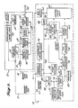
- FIGURE 3 is a block diagram of a microsequencer for use with the central processing unit of the present invention.
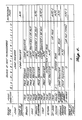
- FIGURE 4 is a table illustrating the method for determining the next microaddress by the microsequencer.
- FIGURE 5 is a table indicating the control signals that may be used to modify the next microaddress.
- FIGURE 6 is a block diagram detailing the control logic unit of the central processing unit of the present invention.
- FIGURE 1 illustrates a computer system which includes a preferred embodiment of the central processing unit of the present invention. The computer system includes central processing unit (CPU) 10, system bus 20,
memory array 22, andconsole terminal 24. The computer system can also include various peripheral devices (not shown) connected to system bus 20, for example disk controllers and network interfaces.Console terminal 24 may be omitted if a suitable interface is provided on bus 20, e.g., an interface to a local area network.CPU 10 consists ofmemory control module 12 anddata path module 14. The actual execution of program instructions is controlled bydata path module 14, andmemory control module 12 acts generally as an interface between the data path module and the system bus. The memory control and data path modules communicate via memory control bus 16 andmemory data bus 18. -
Memory control module 12 is a microprogrammed device that operates asynchronously with respect todata path module 14. The memory control module provides an interface between the CPU and the system bus and, in addition, provides address translation, instruction prefetch, and data cache functions fordata path module 14. Address translation refers to the translation of virtual addresses specified bydata path module 14 into actual physical addresses. The term data cache refers to means for the storage of recently used data in high speed memory arrays within the CPU. - Referring now to FIGURE 2,
memory control module 12 includestransceiver 30,buses 32 and 34, translation buffer/cache 40,physical address register 42,system bus interface 44, merge/rotate unit 48, microsequencer/control store 50,bus controller 52, and instruction prefetch unit 56. The function of the memory control units will be described by outlining the sequence of operations that takes place whendata path module 14 requests that data be read from a specified virtual address. The data path module places the virtual address in bus latch 64 from which point it is sent tomemory control module 12 overmemory data bus 18. The address passes throughtransceiver 30 ontobus 32. The virtual address onbus 32 is presented to translation buffer/cache 40 and if the required translation entry is present (i.e., a cache hit), the corresponding physical address is produced on bus 34. From bus 34, the physical address is loaded intophysical address register 42, from which point it is loaded ontobus 32. The physical address onbus 32 is then simultaneously presented to translation buffer/cache 40 and to the systembus interface unit 44. If the required data is in the cache, the translation buffer/cache 40 asserts the requested data onto bus 34 in the next machine cycle. If a cache miss occurs, a system bus cycle is executed to fetch the requested data frommemory array 22. then the data is received from memory, it is passed fromsystem bus interface 44 onto bus 34. Once the data from the cache or from memory is received on bus 34, it is loaded through merge/rotateunit 48 back ontobus 32. The requested data is then passed todata path module 14 viatransceiver 30 andmemory data bus 18, completing the virtual read cycle. The above-described sequence of memory control operations is carried out and coordinated by control signals emanating from microsequencer/control store 50. The particular microprogram executed by microsequencer/control store 50 is selected bymemory control command 28 sent bydata path module 14 tomemory control module 12 over memory control bus 16. This command is asserted at the same time that the virtual address is placed onmemory data bus 18. For memory control module microprograms that require the use of system bus 20, the microprograms operate throughbus controller unit 52. - An additional function performed by
memory control module 12 is the prefetching of instructions for execution bydata path module 14. The prefetched instructions are stored in instruction prefetch unit 56, and are passed todata path module 14 as needed, one byte at a time, via memory control bus 16. Memory control bus 16 therefore performs two distinct functions: the transfer of instructions frommemory control module 12 todata path module 14, and the transfer of memory control commands fromdata path module 14 tomemory control module 12. - Each macroinstruction executed by
data path module 14 generally consists of an operation code (op-code) followed by one or more operand specifiers. The operand specifiers specify either the data or the location of the data upon which the macroinstruction is to operate. In the former case, the data contained within the operand specifier is termed a literal. In the latter case, the operand specifier designates the addressing mode and the number (i.e., address) of a register. Examples of addressing modes are direct in which the designated register contains the data, and indirect, in which the designated register contains the address of the data. By way of example, in a macroinstruction to add the contents ofregisters register 3 direct and register 4 direct, respectively. In the preferred embodiment described herein, each op-code and operand specifier consists of one or more bytes, and such macroinstruction bytes are received and processed one byte at a time bydata path module 14. - Referring now to
data path module 14 in FIGURE 2, the execution of macroinstructions is carried out by means of microinstructions executed by control logic unit 60. The control logic unit includes the ALU, the general purpose registers, two pointer registers, the macroprogram counter, and other elements as described below. For each macroinstruction, control logic unit 60 executes a series of microinstructions stored incontrol store 62. The microinstruction sequence commences when the op-code of a new macroinstruction is loaded into instruction register 70 from memory control bus 16. The value of the op-code and a portion of the current microinstruction are used to address a location indecode ROM 74. In response, the decode ROM supplies a number of outputs: a next microaddress, which specifies the address incontrol store 62 of the first microinstruction corresponding to the macroinstruction op-code; a SIZE signal indicating the length in bytes of the data upon which the macroinstruction is to operate; and a CC CLASS (condition code class) signal whose function is described below. When the instruction register contains an operand specifier, decodeROM 74 in addition supplies a REGISTER signal indicating whether or not the addressing mode is direct. - The next microaddress supplied by
decode ROM 74 is passed bymicrosequencer 76 to controlstore address register 78. The address in controlstore address register 78 specifies the microinstruction which is accessed incontrol store 62. Portions of the accessed microinstruction are routed to a number of destinations. One portion goes to control logic unit 60 for execution. A second portion goes tomicrosequencer 76 where it can be used to determine the address of the next microinstruction. In certain situations,control store 62 also suppliesmemory control signal 28 and values to be loaded intosize register 88 andCC logic 90. After the first microinstruction has begun executing,microsequencer 76 causes the address of the next microinstruction to be placed into controlstore address register 78, and the sequence continues until all microinstructions corresponding to the macroinstruction have been executed.Microstack 80 is included to permit the use of microsubroutines and microtraps in the microprograms incontrol store 62. The operation of the microstack is described in detail below. - Other elements included in
data path module 14 are bus latch 64,buses latch 86,size register 88,condition code logic 90,index register 92,console interface 94, interruptcontrol logic 96, andinstruction register buffer 98.Buses Latch 86 provides isolation betweenbuses register 88 is used to hold a code, usually derived from the SIZE signal fromdecode ROM 74 or fromcontrol store 62, indicating a default data path width for control logic unit 60.Condition code logic 90 is used to control the setting of macrolevel condition codes based on control logic unit 60 outputs. Index register 92 is a four-bit register that may be used bymicrosequencer 76 to determine the next microaddress.Console interface 94 is a serial port used to interface the data path module with console terminal 24 (FIGURE 1). Interruptcontrol logic 96 compares any interrupt received from system bus 20 with the current state of the CPU, to determine whether the interrupt should be taken.Instruction register buffer 98 provides a means for sending the contents ofinstruction register 70 to control logic unit 60 viabus 82. - The function of
microsequencer 76 is to determine the sequence in which microinstructions are executed by control logic unit 60. It accomplishes this by determining, during the execution of a given microinstruction, the address incontrol store 62 of the next microinstruction, and placing that address in controlstore address register 78. The microsequencer determines the next microinstruction address based on information coded into the current microinstruction, and on the signals on various status and control lines. - FIGURE 3 illustrates
microsequencer 76 in greater detail. The next microaddress is determined by the output of MUX (multiplexer) 200. The inputs to MUX 200 arepage register 201,microprogram counter 202, andOR gate 204. The selection between these inputs is determined by the output ofJUMP MUX 206 and by certain other control signals to be described.Page register 201 contains the high order bits of the current microinstruction address. Microprogram counter 202 contains the low order bits of the current microinstruction address, plus one.Page register 201 andmicroprogram counter 202 therefore together point to the next sequential microinstruction address. The selection of these inputs byMUX 200 represents the simple case in which the computer system executes microinstructions in a sequential fashion. - OR
gate 204 performs a logical OR operation between the output ofOR MUX 208 and the address onbus 210.Bus 210 contains an address determined either bydecode ROM 74,jump register 212, ormicrostack 80. Thebus 210 address is derived fromdecode ROM 74 when a macroinstruction op-code or operand specifier byte is being decoded. In this case, the decode ROM provides either all or part of the address of the first microinstruction required to carry out the function specified by this macroinstruction byte. In general,jump register 212 is the source of the address onbus 210 when a nonsequential jump or branch is to be taken in the microinstruction sequence. The address to which the branch is to be taken is derived from the contents of the current microinstruction incontrol store 62 and placed injump register 212. Finally, microstack 80 is the source of the address onbus 210 when a return from a microsubroutine or microtrap is to be taken. The return address is stored inmicrostack 80 when the original subroutine call or trap is taken. The return address is determined either by the contents ofpage register 201 andmicroprogram counter 202 for a subroutine call, or by the contents of the page register and the microprogram counter less one (i.e., the current microaddress) for a trap. In the latter case,conditional decrementer 214 is used to subtract one from the contents ofmicroprogram counter 202. - Each microinstruction stored in
control store 62 includes three fields: a data path control field, a condition code/size field, and a next address control field. The data path control field is used to control the execution of the microinstruction by control logic unit 60 (FIGURE 2). The condition code/size field is discussed below. The next address control field is used bymicrosequencer 76 to determine the address of the next microinstruction. The next address control field can conceptually be broken down into four subfields as follows:
Type
Jump Condition
OR
Jump Address
The Type subfield specifies one of the branch types listed in FIGURE 4 and explained more fully below. The Jump Condition subfield specifies the condition to be tested to determine whether or not a nonsequential branch is to be taken in the microinstruction sequence. Referring to FIGURE 3, the Jump Condition subfield in part determines which of the inputs toJUMP MUX 206 is selected for controllingMUX 200. Typical Jump Conditions which may be selected are the ALU condition codes, whether or not an interrupt or console halt has been received, whether or not the outputs ofOR MUX 208 are zero, and whether the signal IR INVALID has been asserted. The IR INVALID signal is generated by instruction prefetch unit 56 wheneverinstruction register 70 does not contain valid information. In general, if the selected condition is true, thenMUX 200 selects the address supplied byOR gate 204 and the branch is taken. If the condition is not true,MUX 200 selects the next sequential address supplied bypage register 201 andmicroprogram counter 202. - The OR operation performed by
OR gate 204 only operates on the less significant bits of the address onbus 210. In a preferred embodiment of the present computer system, the output ofOR MUX 208 is four bits wide, and, for certain microinstruction branch types, these four bits are ORed with the low order four bits onbus 210. The OR MUX is thus capable of providing multidestination branching (i.e., casing). The output ofOR MUX 208 is controlled by the OR subfield of the current microinstruction. FIGURE 5 shows one preferred embodiment of the present invention in which the OR subfield is up to three bits wide and capable of selecting from up to eight sets of four bit inputs. For each selection, corresponding to OR subfield values zero through seven, FIGURE 5 lists the values for each of the OR MUX output bits ORMUX3 through ORMUX0. For a subfield value of zero, all OR MUX outputs are zero. For a value of one, ORMUX0 is set to one if the IR INVALID signal is asserted. For a value of two, ORMUX1 is set to one. This value may convenienuy be used to provide multiple returns from microsubroutines. For a value of three, the OR flux output is determined by the signals on four memory control status lines as indicated. MEM ERR refers to a miscellaneous error signal frommemory control module 12. PAGE CROSSING indicates an attempt to access data that crosses a 512 byte page boundary. TB MISS indicates that a translation entry for a requested virtual address was not found in translation buffer/cache 40. MODIFY REFUSE indicates that a memory write operation could not be performed because the modify bit in the corresponding translation buffer entry was not set. For a code value of four, the OR MUX output is determined by the IR INVALID signal and by BR FALSE, the latter indicating whether a macrolevel branch will be taken. For a code value of five, the OR Mux output is determined by the indicated status signals. OVERFLOW refers to the PSL V code described below. INTERRUPT and CONSOLE HALT refer to signals from interruptcontrol logic 96 andconsole interface 94, respectively. For a code value of six, the OR MUX output is equal to the contents of index register 92 (FIGURE 2). For a code value of seven, the OR MUX output is determined by the contents ofsize register 88. - FIGURE 4 summarizes the methods by which
microsequencer 76 selects the next microaddress. The Type subfield of the current microinstruction specifies one of the branch types listed in the first column of FIGURE 4. The operation of these types is described in the following paragraphs. In FIGURE 4, the symbol µPC stands formicroprogram counter 202. - When the branch type is Jump or Jump to Subroutine, the address contained in the Jump Address subfield of the current microinstruction is loaded into
Jump Register 212. This address is enabled ontobus 210, from which point it passes without modification through ORgate 204 andMUX 200. The next microaddress is therefore determined entirely by the Jump Address subfield of the current microinstruction. Jump and Jump to Subroutine branch types are used to cause unconditional branches in microinstruction flow. When a Jump to Subroutine is executed, the contents ofpage register 201 andmicroprogram counter 202 are pushed ontomicrostack 80. - A branch type of Branch is used to perform a conditional Jump to a microaddress within the current page. As indicated in FIGURE 4, the high order five bits of the next microaddress are determined by
page register 201, and the low order eight bits are determined based on the Jump Condition. If the Jump Condition is true, the low order bits are derived from the low-order Jump Address subfield of the current microinstruction viaJump Register 212. If the Jump Condition is false, no jump is taken, and the low order bits are derived frommicroprogram counter 202. The Jump Condition is equal to the signal selected byJump MUX 206 based upon the Jump Condition subfield of the current microinstruction. - The Case branch type is similar to Branch, except that if the Jump Condition is true, the low order bits of the next microaddress are determined by the Jump Register in combination with the OR MUX output. In particular, the four OR MUX output bits (FIGURE 5) are ORed with the low order four bits of the Jump Register by
OR gate 204. - The Branch to Subroutine and Trap branch types are similar to Case, except that if the Jump Condition is true, the high order bits of the next microaddress are forced to zero, and either the next sequential microaddress (Branch to Subroutine) or the current microaddress (Trap) are pushed onto
microstack 80. - The Return branch type is used to return to any microaddress which has been pushed onto
microstatck 80. The Return branch type is conditional, and will only return if the Jump Condition is true. A false Jump Condition will cause the next sequential microaddress to be selected bymicrosequencer 76. - FIGURE 4 also illustrates the way that the next microaddress is determined when control logic unit 60 executes a microinstruction which calls for the decoding of an op-code or an operand specifier in
instruction register 70. For an op-code decode, the next microaddress is determined by the address supplied bydecode ROM 74 if the specified Jump Condition is false. In this event, the high order bit of the next microaddress is set to zero. However, if the specified Jump Condition is true, then the next microaddress is determined entirely by the four bit output of ORflux 208, and the current microaddress is pushed ontomicrostack 80. In general, the Jump Condition specified in an op-code decode microinstruction will be the IR INVALID signal. As a result, whendata path module 14 attempts to decode an op-code which is not yet available ininstruction register 70, a trap is taken to a low microaddress where a subroutine waits for instruction prefetch unit 56 to catch up. - When an operand specifier decode microinstruction is executed, the next microaddress is determined by two signals: the IR INVALID signal and the REGISTER signal supplied by
decode ROM 74, the latter indicating whether the addressing mode of the operand specifier is direct. If the instruction register is valid and the mode is direct, then the next sequential microaddress is selected. If the instruction register is valid and the mode is indirect, then the microprogram jumps to a subroutine at an address whose high order portion is determined by the high-order bits ofJump Register 212, and whose low order portion is equal to the microaddress supplied bydecode ROM 74. The address inJump Register 212 is derived from Jump Address subfield of the current microinstruction. Finally, if the IR INVALID signal is asserted, then the microprogram traps to a subroutine whose address is specified by the output of ORflux 208, which in this case is set to a value equal to one. - The last situation illustrated in FIGURE 4 is power-up or a parity error. In this case,
data path module 14 begins executing microinstructions at address zero. - FIGURE 6 illustrates control logic unit 60 in greater detail. The control logic unit includes
buses barrel shifter 108 and associatedshift count register 110 and resultregister 112, pointer registers 120 and 122,register file 124,program counter 126,constant ROM 130, register savestack 132, I/O port 134, and control store register 140. - The execution of a microinstruction by control logic unit 60 commences when the data path control field of the microinstruction is loaded into control store register 140 from
control store 62. In general, the data path control field includes a micro op-code and two micro operand specifiers. When the micro op-code specifies an arithmetic or logical operation (e.g., Add, And, Mask, Compare), the operation is carried out by ALU 104. The two required operands are supplied viabuses -
Barrel shifter 108 is used for shift operations. The shift count may be stored inshift count register 110 or supplied as a literal in the microinstruction. The result of the shift operation is stored inresult register 112. -
Register file 124 contains a number of general registers accessible to the macrolevel program, plus both general and special purpose microlevel registers. The term general register will hereafter be used to refer to both macrolevel and microlevel general purpose registers inregister file 124. Each register may be read from eitherbus bus 102. Each register inregister file 124 has a unique register address associated with it, the register address being used as described below to specify the register during microinstruction execution. - Size
register 88 is used to control the width of the data path utilized by control logic unit 60, and to control microprogram branching as indicated in FIGURE 5. In a preferred embodiment of the present computer system, the data path can be up to 32 bits wide, although particular macroinstructions may specify a smaller data path such as byte (eight bits) and word (16 bits). For example, a macroinstruction might specify that a byte is to be retrieved from a particular virtual memory address and loaded into general register 3 (i.e., the general register inregister file 124 having a register address of 3). This macroinstruction would affect only the low order eight bits ofgeneral register 3, leaving thehigh order 24 bits unaffected. A full 32-bit block of data is referred to as a longword. - Size
register 88 is loaded with a two-bit code directly fromdecode ROM 74 when a macroinstruction op-code is decoded. In one preferred embodiment, the coding scheme is:
0 -byte
1 - word
2 - not used
3 - longword
Thus the data path width specified by an op-code can be made available to the control logic unit (as signals SIZE0 and SIZE1) during the entire execution sequence for that op-code, without the use of ALU operations for masking, and without any moving, rotating, or refreshing of the register. - The contents of the size register can be altered when a microinstruction for performing an operand specifier decode is executed. When such a microinstruction is executed, the condition code/size field of the microinstruction is loaded from
control store 62 intosize register 88 if the value of the field is zero (byte), 1 (word), or 3 (longword). If the value is 2, then thesize register 88 is unaffected, leaving intact the size specified by the preceding op-code. - Aside from decode microinstructions, the size register can be modified only by Move microinstructions that explicitly specify the size register as their destination operands. Microinstructions other than decodes can, however, control the data path width during their execution by means of their condition code/size field. For ALU and shift microinstructions, the condition code/size coding is discussed below. For other microinstructions, (e.g., Move, Memory Request), the condition code/size field coding is as follows:
0 - byte
1 - word
2 - use size register
3 - longword
Thus a given microinstruction can either specify its own data path width, or can specify the size register and therefore use the width specified by a preceding op-code or operand specifier. The result is that the efficiency gained by the use ofsize register 88 does not cause any corresponding loss of flexibility in the microprogramming of the present computer system. - Pointer registers 120 and 122 are six-bit registers that can each serve two functions: they can contain the address of (i.e., point to) a particular general register in
register file 124, or they can contain a literal value derived from an operand specifier. Pointer registers 120 and 122 can be read frombuses bus 102. The use of two pointer registers provides significant advantages in the execution speed of many macroinstructions. For example, a macroinstruction to add the contents of general registers R1 and R2, placing the result in general register R2, might be coded as follows:Op-code - Add Operand specifier 1 - R1, direct mode Operand specifier 2 - R2, direct mode - 1. Decode op-code
- 2.
Decode operand specifier 1 - 3. Move R1 to TEMP1
- 4.
Decode operand specifier 2 - 5. Move R2 to TEMP2
- 6. Add TEMP3 = TEMP1 + TEMP2
- 7. Move TEMP3 to R2
- 1. Decode op-code
- 2.
Decode operand specifier 1, place address of R1 in PTR1 - 3.
Decode operand specifier 2, place address of R2 in PTR2 - 4. Add TEMP1 = @PTR1 @PTR2
- 5. Move TEMP1 to @PTR2
- The Add and Move microinstructions in
steps register file 124, and is used to specify the contents of that register. For example, for a microinstruction such asMove register file 124 whose addresses are 3 and 4 respectively, the result would be that the contents ofregister 3 would be moved to register 4. Pointer registers 120 and 122 provide a different and generally more efficient method of accomplishing the same result. Each pointer register is assigned a unique indirect address different from the direct address of any register. When the indirect address is specified by a micro operand specifier, the register actually accessed is determined by the contents of the indirectly addressed pointer register. For example, if pointer registers 120 and 122 were assigned indirect addresses of 54 and 55, and contained thenumbers Move -
Program counter 126 is a register which stores the address of the next macroinstruction byte to be executed. As withpointer registers register file 124,program counter 126 may be read from eitherbus bus 102.Program counter 126 is automatically incremented, by 1, 2 or 4, when one of the following occurs: - (1) An op-code decode microinstruction is executed.
- (2) An operand specifier decode microinstruction is executed.
- (3) The current microinstruction specifies
instruction register 70 as the location of one of the microinstruction operands. - (4) A microinstruction is executed which specifies retrieval of data from the macroinstruction instruction stream.
- Cases (1) and (2) have already been described.
Program counter 126 is incremented by one whenever a new macroinstruction byte is clocked out of theinstruction register 70, such that the address inprogram counter 126 corresponds to the virtual address of the new macroinstruction byte. An example of case (3) is a situation in which a byte in the macroinstruction stream contains literal data. For example, one type of operand specifler specifies the address of the operand by specifying a register which contains a base address, and a fixed offset to be added to the base address found in the register. In this situation, the operand specifier would consist of two bytes, the first byte specifying the register address (e.g., register 2) and the addressing mode, and the second byte containing the fixed offset (i.e., a literal). The microinstructions for accessing such an operand would begin by decoding the first operand specifier byte and putting the value 2 (the register address) inpointer register 120. The following microinstruction would then Add the value pointed to bypointer register 120 to the literal contained ininstruction register 70. The microinstruction would referenceinstruction register 70 by specifying a unique register address assigned to the instruction register. The literal would reach ALU 104 frominstruction register 70 throughinstruction register buffer 98,bus 82,latch 86,bus 84, I/O port 134 andbus 102. The execution of the Add microinstruction specifying the address ofinstruction register 70 as an operand causesprogram counter 126 to be incremented by 1. - Case (4) listed above is termed an instruction stream memory request. When such a microinstruction is executed, control signals are sent from
control store 62 tomemory control module 12 via memory control bus 16. At the same time, the unincremented contents ofprogram counter 126 are driven ontobus 84 viabus 102 and I/O port 134, and from there sent tomemory control module 12 viamemory data bus 18.Program counter 126 is then incremented by 1, 2 or 4, depending upon whether the instruction stream memory request microinstruction specified a byte, word or a longword. On memory control module 12 (FIGURE 2), instruction prefetch unit 56 maintains a prefetch buffer filled with macroinstruction stream bytes. An instruction stream memory request first clears the prefetch buffer, then reads a byte, word, or longword from translation buffer/cache 40 ormemory array 22 and sends the resulting data todata path module 14 viamemory data bus 18. Instruction prefetch unit 56 then refills the prefetch buffers beginning with the next byte in the macroinstruction stream following the bytes sent todata path module 14. - Register save
stack 132 is a LIFO stack used to temporarily store the contents of specified registers. Each entry on the stack consists of the contents of a register plus the address (number) of that register. An example illustrating the use of the register save stack is the decoding of an operand specifier that specifies an autoincrement addressing mode. In such a mode, the contents of a specified register is first used as an address to access the operand, and the register is then automatically incremented by 1, 2 or 4. When autoincrement mode operand specifier is decoded, the unincremented contents of the register are automatically pushed onto the register save stack. If the attempted memory access then results in an error condition, the register can be restored to its preexisting condition by popping the stack. The push operation is controlled by the current microinstruction, which contains a bit that determines whether or not a push will occur. If a push is to occur, one of the micro operand specifiers contains the address of the register. - Condition
code logic unit 90 is used for storing and controlling two sets of condition codes: microprogram level (ALU) condition codes and macroprogram level (PSL) condition codes. Four conditions are provided at each level:
N- negative
Z - zero
V - overflow
C - carry
The ALU condition codes reflect the result of the last microinstruction executed by control logic unit 60, which specified in the condition code/size field that the ALU condition codes were to be loaded, and comprise four of the inputs to JUMP flux 206 (FIGURE 3). The ALU condition codes can therefore be used as jump control signals by microinstructions, as indicated in FIGURE 4. The PSL condition codes are the condition codes available to the macroprogram level, and may be used by the macroprogram to determine whether a macrobranch should be taken. - When an op-code is decoded by
decode ROM 74, a two-bit Condition Code Class signal is produced and sent directly to a condition code class register (not shown) contained within conditioncode logic unit 90. The contents of the condition code class register determine how the ALU codes are mapped to the PSL codes as follows:Condition Code Class Register Class 0 Logical ALU N to PSL N ALU Z to PSL Z ALU V to PSL V PSL C to PSL C 1 Arithmetic ALU N to PSL N ALU Z to PSL Z ALU V to PSL V ALU C to PSL C 2 Compare ALU N to PSL N ALU Z to PSL Z Clear PSL V ALU C to PSL C 3 Floating Point ALU N to PSL N ALU Z to PSL Z ALU V to PSL V Clear PSL C - The actual setting of condition codes by a given microinstruction is determined by the condition code/size field of that microinstruction. As described above, certain types of microinstructions (e.g., Move, Memory Request, Decode) use the condition code/size field to specify data path width, and for these microinstructions, the condition codes are never set. For other microinstructions (e.g., Add, And, Shift) the condition code/size field controls data path width and condition code setting as follows:
Condition Code/Size Field Value Data Path Width 0 longword conditions codes not affected 1 longword set ALU condition codes 2 longword set ALU & PSL condition codes 3 per size register set ALU & PSL condition codes CC logic unit 90 fromcontrol store 62.
Claims (7)
Applications Claiming Priority (3)
| Application Number | Priority Date | Filing Date | Title |
|---|---|---|---|
| US538373 | 1983-10-03 | ||
| US06/538,373 US4586130A (en) | 1983-10-03 | 1983-10-03 | Central processing unit for a digital computer |
| EP84306436A EP0138419B1 (en) | 1983-10-03 | 1984-09-20 | Central processing unit for a digital computer |
Related Parent Applications (1)
| Application Number | Title | Priority Date | Filing Date |
|---|---|---|---|
| EP84306436.1 Division | 1984-09-20 |
Publications (3)
| Publication Number | Publication Date |
|---|---|
| EP0415461A2 true EP0415461A2 (en) | 1991-03-06 |
| EP0415461A3 EP0415461A3 (en) | 1991-08-07 |
| EP0415461B1 EP0415461B1 (en) | 1995-07-19 |
Family
ID=24146659
Family Applications (2)
| Application Number | Title | Priority Date | Filing Date |
|---|---|---|---|
| EP90118287A Expired - Lifetime EP0415461B1 (en) | 1983-10-03 | 1984-09-20 | Central processing unit supporting variable length instructions |
| EP84306436A Expired - Lifetime EP0138419B1 (en) | 1983-10-03 | 1984-09-20 | Central processing unit for a digital computer |
Family Applications After (1)
| Application Number | Title | Priority Date | Filing Date |
|---|---|---|---|
| EP84306436A Expired - Lifetime EP0138419B1 (en) | 1983-10-03 | 1984-09-20 | Central processing unit for a digital computer |
Country Status (6)
| Country | Link |
|---|---|
| US (1) | US4586130A (en) |
| EP (2) | EP0415461B1 (en) |
| JP (3) | JPS60107138A (en) |
| AT (2) | ATE125374T1 (en) |
| CA (1) | CA1230181A (en) |
| DE (2) | DE3486399T2 (en) |
Cited By (1)
| Publication number | Priority date | Publication date | Assignee | Title |
|---|---|---|---|---|
| US7376814B1 (en) | 1999-09-07 | 2008-05-20 | Nxp B.V. | Method for forming variable length instructions in a processing system |
Families Citing this family (32)
| Publication number | Priority date | Publication date | Assignee | Title |
|---|---|---|---|---|
| US4812971A (en) * | 1983-10-03 | 1989-03-14 | Digital Equipment Corporation | Central processing unit for a digital computer |
| US5034879A (en) * | 1984-10-01 | 1991-07-23 | Unisys Corp. (Formerly Burroughs Corp.) | Programmable data path width in a programmable unit having plural levels of subinstruction sets |
| JPS6282402A (en) * | 1985-10-07 | 1987-04-15 | Toshiba Corp | Sequence controller |
| JPH0827716B2 (en) * | 1985-10-25 | 1996-03-21 | 株式会社日立製作所 | Data processing device and data processing method |
| US4709324A (en) * | 1985-11-27 | 1987-11-24 | Motorola, Inc. | Data processor control unit having an interrupt service using instruction prefetch redirection |
| US4811266A (en) * | 1986-11-05 | 1989-03-07 | Honeywell Bull Inc. | Multifunction arithmetic indicator |
| KR950006590B1 (en) * | 1986-11-14 | 1995-06-19 | 가부시기가이샤 히다찌세이사꾸쇼 | Microprocessor with a cache memory |
| JP2577023B2 (en) * | 1987-12-28 | 1997-01-29 | 株式会社日立製作所 | Address extension control method for information processing equipment |
| JPH01230125A (en) * | 1988-03-10 | 1989-09-13 | Nec Corp | Data processor having partial updating function of register |
| DE68927313T2 (en) * | 1988-06-27 | 1997-05-07 | Digital Equipment Corp | Operand specifier processing |
| JPH07120278B2 (en) * | 1988-07-04 | 1995-12-20 | 三菱電機株式会社 | Data processing device |
| US5119483A (en) * | 1988-07-20 | 1992-06-02 | Digital Equipment Corporation | Application of state silos for recovery from memory management exceptions |
| US5321823A (en) * | 1988-07-20 | 1994-06-14 | Digital Equipment Corporation | Digital processor with bit mask for counting registers for fast register saves |
| US5023828A (en) * | 1988-07-20 | 1991-06-11 | Digital Equipment Corporation | Microinstruction addressing in high-speed CPU |
| US5019967A (en) * | 1988-07-20 | 1991-05-28 | Digital Equipment Corporation | Pipeline bubble compression in a computer system |
| US5006980A (en) * | 1988-07-20 | 1991-04-09 | Digital Equipment Corporation | Pipelined digital CPU with deadlock resolution |
| US5590293A (en) * | 1988-07-20 | 1996-12-31 | Digital Equipment Corporation | Dynamic microbranching with programmable hold on condition, to programmable dynamic microbranching delay minimization |
| US5117487A (en) * | 1988-08-26 | 1992-05-26 | Kabushiki Kaisha Toshiba | Method for accessing microprocessor and microinstruction control type microprocessor including pointer register |
| US4994962A (en) * | 1988-10-28 | 1991-02-19 | Apollo Computer Inc. | Variable length cache fill |
| US5148528A (en) * | 1989-02-03 | 1992-09-15 | Digital Equipment Corporation | Method and apparatus for simultaneously decoding three operands in a variable length instruction when one of the operands is also of variable length |
| CA1325288C (en) * | 1989-02-03 | 1993-12-14 | Ricky C. Hetherington | Method and apparatus for controlling the conversion of virtual to physical memory addresses in a digital computer system |
| US5179691A (en) * | 1989-04-12 | 1993-01-12 | Unisys Corporation | N-byte stack-oriented CPU using a byte-selecting control for enhancing a dual-operation with an M-byte instruction word user program where M<N<2M |
| JPH03271829A (en) * | 1990-03-20 | 1991-12-03 | Fujitsu Ltd | Information processor |
| US5448707A (en) * | 1991-10-29 | 1995-09-05 | Intel Corporation | Mechanism to protect data saved on a local register cache during inter-subsystem calls and returns |
| US5715421A (en) * | 1992-10-16 | 1998-02-03 | Seiko Epson Corporation | Apparatus and method of addressing paged mode memory including adjacent page precharging |
| US5832533A (en) * | 1995-01-04 | 1998-11-03 | International Business Machines Corporation | Method and system for addressing registers in a data processing unit in an indexed addressing mode |
| US7181484B2 (en) * | 2001-02-21 | 2007-02-20 | Mips Technologies, Inc. | Extended-precision accumulation of multiplier output |
| US7711763B2 (en) * | 2001-02-21 | 2010-05-04 | Mips Technologies, Inc. | Microprocessor instructions for performing polynomial arithmetic operations |
| US7162621B2 (en) | 2001-02-21 | 2007-01-09 | Mips Technologies, Inc. | Virtual instruction expansion based on template and parameter selector information specifying sign-extension or concentration |
| US7599981B2 (en) * | 2001-02-21 | 2009-10-06 | Mips Technologies, Inc. | Binary polynomial multiplier |
| US7620057B1 (en) * | 2004-10-19 | 2009-11-17 | Broadcom Corporation | Cache line replacement with zero latency |
| FR2951938B1 (en) | 2009-10-30 | 2012-01-06 | Oreal | USE OF A PUNICA GRANATUM EXTRACT TO COMBAT CANITIS |
Citations (3)
| Publication number | Priority date | Publication date | Assignee | Title |
|---|---|---|---|---|
| US4156927A (en) * | 1976-08-11 | 1979-05-29 | Texas Instruments Incorporated | Digital processor system with direct access memory |
| US4236206A (en) * | 1978-10-25 | 1980-11-25 | Digital Equipment Corporation | Central processor unit for executing instructions of variable length |
| US4258419A (en) * | 1978-12-29 | 1981-03-24 | Bell Telephone Laboratories, Incorporated | Data processing apparatus providing variable operand width operation |
Family Cites Families (14)
| Publication number | Priority date | Publication date | Assignee | Title |
|---|---|---|---|---|
| JPS5040738B1 (en) * | 1970-06-11 | 1975-12-26 | ||
| US3725868A (en) * | 1970-10-19 | 1973-04-03 | Burroughs Corp | Small reconfigurable processor for a variety of data processing applications |
| US4104718A (en) * | 1974-12-16 | 1978-08-01 | Compagnie Honeywell Bull (Societe Anonyme) | System for protecting shared files in a multiprogrammed computer |
| JPS5178150A (en) * | 1974-12-27 | 1976-07-07 | Fujitsu Ltd | |
| IN150275B (en) * | 1977-10-25 | 1982-08-28 | Digital Equipment Corp | |
| JPS54102928A (en) * | 1978-01-31 | 1979-08-13 | Fujitsu Ltd | Data reading out control system |
| US4347566A (en) * | 1978-12-11 | 1982-08-31 | Tokyo Shibaura Denki Kabushiki Kaisha | Data processor with register file and arithmetic logic circuit on one chip and register means directly connected to the chip |
| JPS5578343A (en) * | 1978-12-11 | 1980-06-12 | Toshiba Corp | Information processing unit |
| US4293907A (en) * | 1978-12-29 | 1981-10-06 | Bell Telephone Laboratories, Incorporated | Data processing apparatus having op-code extension register |
| JPS5847053B2 (en) * | 1979-11-19 | 1983-10-20 | 株式会社日立製作所 | data processing equipment |
| JPS575153A (en) * | 1980-06-10 | 1982-01-11 | Nippon Telegr & Teleph Corp <Ntt> | Information processor |
| AU556521B2 (en) * | 1981-06-11 | 1986-11-06 | Data General Corporation | Arithmetic unit |
| US4450523A (en) * | 1981-09-11 | 1984-05-22 | Data General Corporation | Apparatus for deriving the current length of varying-length data items in a digital data processing system |
| US4491908A (en) * | 1981-12-01 | 1985-01-01 | Honeywell Information Systems Inc. | Microprogrammed control of extended integer and commercial instruction processor instructions through use of a data type field in a central processor unit |
-
1983
- 1983-10-03 US US06/538,373 patent/US4586130A/en not_active Expired - Lifetime
-
1984
- 1984-09-20 AT AT90118287T patent/ATE125374T1/en active
- 1984-09-20 EP EP90118287A patent/EP0415461B1/en not_active Expired - Lifetime
- 1984-09-20 DE DE3486399T patent/DE3486399T2/en not_active Expired - Fee Related
- 1984-09-20 AT AT84306436T patent/ATE86401T1/en not_active IP Right Cessation
- 1984-09-20 EP EP84306436A patent/EP0138419B1/en not_active Expired - Lifetime
- 1984-09-20 DE DE84306436T patent/DE3486085T2/en not_active Expired - Fee Related
- 1984-10-01 JP JP59204201A patent/JPS60107138A/en active Granted
- 1984-10-02 CA CA000464499A patent/CA1230181A/en not_active Expired
-
1988
- 1988-06-15 JP JP63145987A patent/JPS6446135A/en active Granted
- 1988-06-15 JP JP63145988A patent/JPS6446136A/en active Granted
Patent Citations (3)
| Publication number | Priority date | Publication date | Assignee | Title |
|---|---|---|---|---|
| US4156927A (en) * | 1976-08-11 | 1979-05-29 | Texas Instruments Incorporated | Digital processor system with direct access memory |
| US4236206A (en) * | 1978-10-25 | 1980-11-25 | Digital Equipment Corporation | Central processor unit for executing instructions of variable length |
| US4258419A (en) * | 1978-12-29 | 1981-03-24 | Bell Telephone Laboratories, Incorporated | Data processing apparatus providing variable operand width operation |
Cited By (1)
| Publication number | Priority date | Publication date | Assignee | Title |
|---|---|---|---|---|
| US7376814B1 (en) | 1999-09-07 | 2008-05-20 | Nxp B.V. | Method for forming variable length instructions in a processing system |
Also Published As
| Publication number | Publication date |
|---|---|
| CA1230181A (en) | 1987-12-08 |
| ATE86401T1 (en) | 1993-03-15 |
| EP0138419A3 (en) | 1988-08-10 |
| JPS60107138A (en) | 1985-06-12 |
| DE3486085D1 (en) | 1993-04-08 |
| EP0415461B1 (en) | 1995-07-19 |
| JPS6339931B2 (en) | 1988-08-09 |
| EP0138419A2 (en) | 1985-04-24 |
| JPH0210452B2 (en) | 1990-03-08 |
| CA1250666C (en) | 1989-02-28 |
| US4586130A (en) | 1986-04-29 |
| DE3486399D1 (en) | 1995-08-24 |
| JPH0128415B2 (en) | 1989-06-02 |
| JPS6446135A (en) | 1989-02-20 |
| DE3486085T2 (en) | 1993-10-14 |
| EP0415461A3 (en) | 1991-08-07 |
| EP0138419B1 (en) | 1993-03-03 |
| DE3486399T2 (en) | 1996-04-18 |
| JPS6446136A (en) | 1989-02-20 |
| ATE125374T1 (en) | 1995-08-15 |
Similar Documents
| Publication | Publication Date | Title |
|---|---|---|
| EP0415461B1 (en) | Central processing unit supporting variable length instructions | |
| US6021265A (en) | Interoperability with multiple instruction sets | |
| US5944841A (en) | Microprocessor with built-in instruction tracing capability | |
| US5293592A (en) | Decoder for pipelined system having portion indicating type of address generation and other portion controlling address generation within pipeline | |
| US5249280A (en) | Microcomputer having a memory bank switching apparatus for accessing a selected memory bank in an external memory | |
| US4591972A (en) | Data processing system with unique microcode control | |
| US4569018A (en) | Digital data processing system having dual-purpose scratchpad and address translation memory | |
| EP0730226A2 (en) | Hardware support for fast software emulation of unimplemented instructions | |
| US5940876A (en) | Stride instruction for fetching data separated by a stride amount | |
| KR100465388B1 (en) | Eight-bit microcontroller having a risc architecture | |
| US4812971A (en) | Central processing unit for a digital computer | |
| KR100385495B1 (en) | Processing system with word alignment branch target | |
| US4223381A (en) | Lookahead memory address control system | |
| US4893235A (en) | Central processing unit for a digital computer | |
| US4597041A (en) | Method and apparatus for enhancing the operation of a data processing system | |
| EP0349124B1 (en) | Operand specifier processing | |
| US7340588B2 (en) | Extending the number of instruction bits in processors with fixed length instructions, in a manner compatible with existing code | |
| US5404471A (en) | Method and apparatus for switching address generation modes in CPU having plural address generation modes | |
| EP0374526A2 (en) | Op branching for starting micro-routines | |
| EP0698884A1 (en) | Memory array for microprocessor cache | |
| CA1250666A (en) | Central processing unit for a digital computer | |
| EP0915416B1 (en) | System for allowing a two word instruction to be executed in a single cycle and method therefor | |
| JPH09505428A (en) | Microcontroller with page address mode | |
| EP0110613B1 (en) | Digital data processing system | |
| EP0312183A2 (en) | Digital data processing system |
Legal Events
| Date | Code | Title | Description |
|---|---|---|---|
| PUAI | Public reference made under article 153(3) epc to a published international application that has entered the european phase |
Free format text: ORIGINAL CODE: 0009012 |
|
| AC | Divisional application: reference to earlier application |
Ref document number: 138419 Country of ref document: EP |
|
| AK | Designated contracting states |
Kind code of ref document: A2 Designated state(s): AT BE CH DE FR GB IT LI LU NL SE |
|
| RIN1 | Information on inventor provided before grant (corrected) |
Inventor name: SHORT, ROBERT T. Inventor name: SCHNORR, PETER CHARLES Inventor name: CUTLER, DAVID N. Inventor name: BUTTS, H. BRUCE, JR. |
|
| PUAL | Search report despatched |
Free format text: ORIGINAL CODE: 0009013 |
|
| AK | Designated contracting states |
Kind code of ref document: A3 Designated state(s): AT BE CH DE FR GB IT LI LU NL SE |
|
| 17P | Request for examination filed |
Effective date: 19920203 |
|
| 18W | Application withdrawn |
Withdrawal date: 19931223 |
|
| D18W | Application withdrawn (deleted) | ||
| 17Q | First examination report despatched |
Effective date: 19941108 |
|
| GRAA | (expected) grant |
Free format text: ORIGINAL CODE: 0009210 |
|
| AC | Divisional application: reference to earlier application |
Ref document number: 138419 Country of ref document: EP |
|
| AK | Designated contracting states |
Kind code of ref document: B1 Designated state(s): AT BE CH DE FR GB IT LI LU NL SE |
|
| PG25 | Lapsed in a contracting state [announced via postgrant information from national office to epo] |
Ref country code: NL Free format text: LAPSE BECAUSE OF NON-PAYMENT OF DUE FEES Effective date: 19950719 Ref country code: LI Effective date: 19950719 Ref country code: CH Effective date: 19950719 Ref country code: BE Effective date: 19950719 Ref country code: AT Effective date: 19950719 |
|
| REF | Corresponds to: |
Ref document number: 125374 Country of ref document: AT Date of ref document: 19950815 Kind code of ref document: T |
|
| REF | Corresponds to: |
Ref document number: 3486399 Country of ref document: DE Date of ref document: 19950824 |
|
| ET | Fr: translation filed | ||
| PG25 | Lapsed in a contracting state [announced via postgrant information from national office to epo] |
Ref country code: LU Free format text: LAPSE BECAUSE OF NON-PAYMENT OF DUE FEES Effective date: 19950930 |
|
| ITF | It: translation for a ep patent filed |
Owner name: STUDIO TORTA SOCIETA' SEMPLICE |
|
| PG25 | Lapsed in a contracting state [announced via postgrant information from national office to epo] |
Ref country code: SE Effective date: 19951019 |
|
| NLV1 | Nl: lapsed or annulled due to failure to fulfill the requirements of art. 29p and 29m of the patents act | ||
| PLBE | No opposition filed within time limit |
Free format text: ORIGINAL CODE: 0009261 |
|
| STAA | Information on the status of an ep patent application or granted ep patent |
Free format text: STATUS: NO OPPOSITION FILED WITHIN TIME LIMIT |
|
| 26N | No opposition filed | ||
| PGFP | Annual fee paid to national office [announced via postgrant information from national office to epo] |
Ref country code: FR Payment date: 19980820 Year of fee payment: 15 |
|
| PGFP | Annual fee paid to national office [announced via postgrant information from national office to epo] |
Ref country code: GB Payment date: 19980826 Year of fee payment: 15 Ref country code: DE Payment date: 19980826 Year of fee payment: 15 |
|
| PG25 | Lapsed in a contracting state [announced via postgrant information from national office to epo] |
Ref country code: GB Free format text: LAPSE BECAUSE OF NON-PAYMENT OF DUE FEES Effective date: 19990920 |
|
| GBPC | Gb: european patent ceased through non-payment of renewal fee |
Effective date: 19990920 |
|
| PG25 | Lapsed in a contracting state [announced via postgrant information from national office to epo] |
Ref country code: FR Free format text: LAPSE BECAUSE OF NON-PAYMENT OF DUE FEES Effective date: 20000531 |
|
| PG25 | Lapsed in a contracting state [announced via postgrant information from national office to epo] |
Ref country code: DE Free format text: LAPSE BECAUSE OF NON-PAYMENT OF DUE FEES Effective date: 20000701 |
|
| REG | Reference to a national code |
Ref country code: FR Ref legal event code: ST |