EP0415064A2 - Wiper - Google Patents
Wiper Download PDFInfo
- Publication number
- EP0415064A2 EP0415064A2 EP90113999A EP90113999A EP0415064A2 EP 0415064 A2 EP0415064 A2 EP 0415064A2 EP 90113999 A EP90113999 A EP 90113999A EP 90113999 A EP90113999 A EP 90113999A EP 0415064 A2 EP0415064 A2 EP 0415064A2
- Authority
- EP
- European Patent Office
- Prior art keywords
- wiper
- slide bar
- lip
- wiper lip
- receptacle
- Prior art date
- Legal status (The legal status is an assumption and is not a legal conclusion. Google has not performed a legal analysis and makes no representation as to the accuracy of the status listed.)
- Granted
Links
Images
Classifications
-
- B—PERFORMING OPERATIONS; TRANSPORTING
- B23—MACHINE TOOLS; METAL-WORKING NOT OTHERWISE PROVIDED FOR
- B23Q—DETAILS, COMPONENTS, OR ACCESSORIES FOR MACHINE TOOLS, e.g. ARRANGEMENTS FOR COPYING OR CONTROLLING; MACHINE TOOLS IN GENERAL CHARACTERISED BY THE CONSTRUCTION OF PARTICULAR DETAILS OR COMPONENTS; COMBINATIONS OR ASSOCIATIONS OF METAL-WORKING MACHINES, NOT DIRECTED TO A PARTICULAR RESULT
- B23Q11/00—Accessories fitted to machine tools for keeping tools or parts of the machine in good working condition or for cooling work; Safety devices specially combined with or arranged in, or specially adapted for use in connection with, machine tools
- B23Q11/08—Protective coverings for parts of machine tools; Splash guards
- B23Q11/0875—Wipers for clearing foreign matter from slideways or slidable coverings
-
- F—MECHANICAL ENGINEERING; LIGHTING; HEATING; WEAPONS; BLASTING
- F16—ENGINEERING ELEMENTS AND UNITS; GENERAL MEASURES FOR PRODUCING AND MAINTAINING EFFECTIVE FUNCTIONING OF MACHINES OR INSTALLATIONS; THERMAL INSULATION IN GENERAL
- F16J—PISTONS; CYLINDERS; SEALINGS
- F16J15/00—Sealings
- F16J15/16—Sealings between relatively-moving surfaces
- F16J15/32—Sealings between relatively-moving surfaces with elastic sealings, e.g. O-rings
- F16J15/3204—Sealings between relatively-moving surfaces with elastic sealings, e.g. O-rings with at least one lip
Landscapes
- Engineering & Computer Science (AREA)
- Mechanical Engineering (AREA)
- General Engineering & Computer Science (AREA)
- Polishing Bodies And Polishing Tools (AREA)
- Lubricants (AREA)
- Cleaning In General (AREA)
- Cleaning Implements For Floors, Carpets, Furniture, Walls, And The Like (AREA)
- Adhesive Tape Dispensing Devices (AREA)
- Encapsulation Of And Coatings For Semiconductor Or Solid State Devices (AREA)
- Mechanical Treatment Of Semiconductor (AREA)
- Processing Of Stones Or Stones Resemblance Materials (AREA)
- Rigid Containers With Two Or More Constituent Elements (AREA)
- Nozzles For Electric Vacuum Cleaners (AREA)
- Brushes (AREA)
- Coating Apparatus (AREA)
- Valve-Gear Or Valve Arrangements (AREA)
- Preliminary Treatment Of Fibers (AREA)
- Sealing Devices (AREA)
Abstract
Description
Gegenstand der Erfindung ist ein Abstreifer für die Anordnung zwischen Abdeckkästen einer Teleskopabdeckung oder zwischen dem Support und der Führungsbahn einer Werkzeugmaschine oder für Paletten-Wechsler mit einer Halteleiste, einer darin angeordneten offenen Aufnahme, einer darin befestigten Abstreiferlippe und einer Gleitleiste.The invention relates to a wiper for the arrangement between cover boxes of a telescopic cover or between the support and the guideway of a machine tool or for pallet changers with a retaining strip, an open receptacle arranged therein, a wiper lip fastened therein and a slide strip.
Aus der DE-OS 37 36 628 ist ein verfahrbarer Schiebetische zum Wechseln von Werkzeugen bekannt, bei dem in einem winkelförmigen Formstück Ausnehmungen zur Aufnahme einer Abstreiferleiste mit Abstreifer und eine Bürstenleiste eingearbeitet sind. Bei dieser bekannten Anordnung sind Abstreiferteile in bewegungsrichtung hintereinander angeordnet und beeinflussen sich bezüglich der Abstreif- und Reinigungswirkung gegenseitig nicht. Für den Andruck an die Führungsbahn ist eine besondere Vorrichtung mit Druckfeder vorgesehen.From DE-OS 37 36 628 a movable sliding table for changing tools is known, in which recesses for receiving a wiper strip with wiper and a brush strip are incorporated in an angular shaped piece. In this known arrangement, wiper parts are arranged one behind the other in the direction of movement and do not influence one another with regard to the wiping and cleaning action. A special device with a compression spring is provided for pressing against the guideway.
Aus der DE-AS 18 03 448 ist ein Abstreifer für die Anordnung zwischen Abdeckkästen einer Teleskopabdeckung bekannt, der aus einer Halteleiste, einer darin angeordneten Aufnahme und einer in dieser Aufnahme befestigten Abstreiferlippe besteht. Dieser bekannte Abstreifer hat den Mangel, daß die Abstreiferlippe aus einem relativ harten Material bestehen muß, weil sie gleichzeitig auch eine Stützfunktion hat.From DE-AS 18 03 448 a stripper for the arrangement between cover boxes of a telescopic cover is known, which consists of a retaining strip, a receptacle arranged therein and a stripper lip fastened in this receptacle. This known scraper has the defect that the scraper lip must consist of a relatively hard material because it also has a supporting function.
Davon ausgehend liegt der Erfindung die Aufgabe zugrunde, einen verbesserten Abstreifer zu schaffen, dessen Abstreiflippe keine Stütz- oder Gleitfunktionen übernehmen muß und deshalb aus einem weichen Material mit guten Abstreifeigenschaften bestehen kann und gegen die zu reinigende Führungsbahn vorgespannt wird.Proceeding from this, the object of the invention is to create an improved scraper, the scraper lip of which does not have to perform any supporting or sliding functions and can therefore consist of a soft material with good scraper properties and is biased against the guideway to be cleaned.
Als technische Lösung wird dafür ein Abstreifer vorgeschlagen, bei dem die Gleitleiste U-förmig ausgebildet ist und unter Vorspannung in die Aufnahme eingesetzt ist und bei dem die Abstreiflippe zwischen den vorgespannten Schenkeln der Gleitleiste angeordnet ist.As a technical solution , a wiper is proposed for this purpose, in which the slide bar is U-shaped and is inserted into the receptacle under pretension and in which the wiper lip is arranged between the prestressed legs of the slide bar.
Bei einer praktischen Ausführungsform kann sich die Gleitleiste mit leistenförmigen, elastischen Auskragungen in der Aufnahme abstützen und der Abstreiferlippe beiderseits mit Klemmrippen anliegen.In a practical embodiment, the slide bar can be supported in the receptacle with strip-shaped, elastic projections and the wiper lip can rest on both sides with clamping ribs.
Als Herstellungsmaterial für die Gleitleiste hat sich ein Polytetrafluoräthylen (PTFE) und für die Abstreiferlippe ein thermoplastisches Elastomer bewährt. Die Abstreiferlippe kann aber auch aus einem weichen Filz oder einer Bürste bestehen.A polytetrafluoroethylene (PTFE) and a thermoplastic elastomer for the wiper lip have proven themselves as the production material for the slide bar. The wiper lip can also consist of a soft felt or a brush.
Ein erfindungsgemäß ausgebildeter Abstreifer hat weiterhin den Vorteil, daß die Stütz- und Gleitfunktionen von der Gleitleiste übernommen werden, die deshalb aus einem härteren Material mit guten Gleit- und Verschleißeigenschaften bestehen kann, während die Abstreiferlippe aus einem anderen, weicheren Material mit besseren Abstreif- und Reinigungseigenschaften hergestellt werden kann. Dabei resultiert aus der Vorspannung der Gleitleiste in der Aufnahme der Halteleiste ein die Reinigungswirkung der Abstreiferlippe verbessernder Druck auf die zu reinigende Unterlage.A scraper designed according to the invention has the further advantage that the support and sliding functions are taken over by the slide bar, which can therefore consist of a harder material with good sliding and wear properties, while the scraper lip made of a different, softer material with better scraper and Cleaning properties can be produced. The prestressing of the slide bar in the receptacle of the holding bar results in a pressure on the surface to be cleaned which improves the cleaning effect of the wiper lip.
Weitere Einzelheiten und Vorteile ergeben sich aus der nachfolgenden Beschreibung der zugehörigen Zeichnungen, in denen bevorzugte Ausführungsbeispiele eines erfindungsgemäß ausgebildeten Abstreifers für zwei verschiedene Anwendungen schematisch dargestellt worden sind. In den Zeichnungen zeigen:
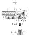
- Fig. 1 einen Abstreifer für die Anordnung zwischen Abdeckkästen einer Teleskopabdeckung im Querschnitt;
- Fig. 2 eine Abstreiferlippe aus Filz;
- Fig. 3 eine Abstreiferlippe in Bürstenform;
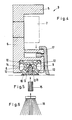
- Fig. 4 einen Abstreifer für die Anordnung zwischen dem Support und der Führungsbahn einer Werkzeugmaschine im Querschnitt;
- Fig. 5 eine Abstreiferlippe aus Filz;
- Fig. 6 eine Abstreiferlippe in Bürstenform.
- 1 shows a wiper for the arrangement between cover boxes of a telescopic cover in cross section.
- 2 shows a wiper lip made of felt;
- 3 shows a wiper lip in the form of a brush;
- 4 shows a wiper for the arrangement between the support and the guideway of a machine tool in cross section;
- 5 shows a wiper lip made of felt;
- Fig. 6 is a wiper lip in the form of a brush.
Ein Abstreifer A für die Anordnung zwischen den Abdeckkästen einer Teleskopabdeckung hat eine Halteleiste 1 mit einem waagerechten Schenkel 2 für die Auflage einer Deckwand 3 eines Abdeckkastens unter Zwischenlage eines zweiseitigen Klebebandes 4.A stripper A for the arrangement between the cover boxes of a telescopic cover has a retaining strip 1 with a
Ein Abstreifer B für die Anordnung zwischen dem Support und der Führungsbahn einer Werkzeugmaschine hat eine Halteleiste 5 mit einem senkrechten Schenkel 6 und einer Bohrung zum Einsetzen einer Befestigungsschraube 7.A stripper B for the arrangement between the support and the guideway of a machine tool has a
In den Halteleisten 1 und 5 beider Abstreifer A und B ist eine kammerartige, offene Aufnahme 8 vorgesehen, in die einer U-förmige Gleitleiste 9 unter Vorspannung eingesetzt ist, welche mit ihren Schenkeln 10,11 aus der Aufnahme 8 herausragt. Am äußeren Umfang der Gleitleiste sind leistenförmige, elastische Auskragungen 12 vorgesehen, die sich in der Aufnahme 8 abstützen. An der Innenseite der beiden Schenkel 10,11 sind Klemmrippen 13 angeordnet, welche die Vorspannung auf eine Abstreiferlippe 14 übertragen.In the
Während die Gleitleiste 9 aus einem härteren Werkstoff wie beispielsweise PTFE bestehen kann, ist es möglich, für die Abstreiferlippe ein anderes Material mit besseren Reinigungseigenschaften, beispielsweise ein thermoplastisches Elastomer zu benutzen.While the
Die Abstreiferlippe 14 kann aber auch aus einem Filz 15 oder einer Bürste 16 bestehen. Dabei werden sowohl der Filz 15 als auch die Bürste 16 zwischen die Schenkel 10,11 der Gleitleiste 9 eingesetzt, damit sie unter Vorspannung gehalten werden.The wiper lip 14 can also consist of a felt 15 or a
Bei beiden Ausführungsbeispielen sind die Halteleisten 1 und 5 an der Vorderseite mit einer Deckleiste 17 abgedeckt.In both embodiments, the
- 1 Halteleiste1 retaining bar
- 2 Schenkel2 legs
- 3 Deckwand3 top wall
- 4 Klebeband4 adhesive tape
- 5 Halteleiste5 retaining strips
- 6 Schenkel6 legs
- 7 Befestigungsschraube7 fastening screw
- 8 Aufnahme8 recording
- 9 Gleitleiste9 slide bar
- 10 Schenkel10 legs
- 11 Schenkel11 legs
- 12 Aufkragung12 cantilever
- 13 Klemmrippe13 clamping rib
- 14 Abstreiferlippe14 wiper lip
- 15 Filz15 felt
- 16 Bürste16 brush
- 17 Deckleiste17 cover strip
- A AbstreiferA scraper
- B AbstreiferB wipers
Claims (6)
dadurch gekennzeichnet,
daß die Gleitleiste (9) U-förmig ausgebildet und in die Aufnahme (8) eingesetzt ist und
daß die Abstreiferlippe (14) zwischen den vorgespannten Schenkeln (10,11) der Gleitleiste (9) angeordnet ist.1. Scraper for the arrangement between cover boxes of a telescopic cover or between the support and the guideway of a machine tool or for pallet changers with a holding bar (1,5), an open receptacle (8) arranged therein, a scraper lip (14) fastened therein and a slide bar (9),
characterized by
that the slide bar (9) is U-shaped and inserted into the receptacle (8) and
that the wiper lip (14) is arranged between the prestressed legs (10, 11) of the slide bar (9).
Priority Applications (1)
| Application Number | Priority Date | Filing Date | Title |
|---|---|---|---|
| AT90113999T ATE90254T1 (en) | 1989-08-28 | 1990-07-21 | STRIPPER. |
Applications Claiming Priority (2)
| Application Number | Priority Date | Filing Date | Title |
|---|---|---|---|
| DE3928380A DE3928380A1 (en) | 1989-08-28 | 1989-08-28 | SCRAPER |
| DE3928380 | 1989-08-28 |
Publications (3)
| Publication Number | Publication Date |
|---|---|
| EP0415064A2 true EP0415064A2 (en) | 1991-03-06 |
| EP0415064A3 EP0415064A3 (en) | 1991-05-08 |
| EP0415064B1 EP0415064B1 (en) | 1993-06-09 |
Family
ID=6388025
Family Applications (1)
| Application Number | Title | Priority Date | Filing Date |
|---|---|---|---|
| EP90113999A Expired - Lifetime EP0415064B1 (en) | 1989-08-28 | 1990-07-21 | Wiper |
Country Status (14)
| Country | Link |
|---|---|
| EP (1) | EP0415064B1 (en) |
| JP (1) | JPH0710477B2 (en) |
| KR (1) | KR960011991B1 (en) |
| CN (1) | CN1049994A (en) |
| AT (1) | ATE90254T1 (en) |
| BR (1) | BR9004215A (en) |
| CZ (1) | CZ280141B6 (en) |
| DD (1) | DD297101A5 (en) |
| DE (2) | DE3928380A1 (en) |
| ES (1) | ES2043195T3 (en) |
| HU (1) | HUT55665A (en) |
| PL (1) | PL286646A1 (en) |
| RU (1) | RU1797554C (en) |
| YU (1) | YU161590A (en) |
Families Citing this family (6)
| Publication number | Priority date | Publication date | Assignee | Title |
|---|---|---|---|---|
| JPH04118455A (en) * | 1990-04-11 | 1992-04-20 | Sankyo:Kk | Metal wall plate for curved face and its manufacture |
| DE19518834C2 (en) * | 1995-05-23 | 2003-07-03 | Ina Schaeffler Kg | Scraper device for a rail guide |
| ES2156482B1 (en) * | 1998-03-23 | 2002-01-16 | Irudex S A | CLEANING DEVICE FOR FLAT SURFACES, ESPECIALLY MACHINES. |
| ATE334780T1 (en) * | 2001-09-25 | 2006-08-15 | Schneeberger Holding Ag | STRIPPER DEVICE |
| DE10344246A1 (en) * | 2003-09-23 | 2005-04-21 | Kabelschlepp Gmbh | Sliding seal for processing equipment is prepared from a universal blank cut to size and assembled on a support mounting |
| TWI725392B (en) | 2019-03-12 | 2021-04-21 | 緯創資通股份有限公司 | Monitoring system and monitoring method thereof |
Citations (3)
| Publication number | Priority date | Publication date | Assignee | Title |
|---|---|---|---|---|
| DE3545168A1 (en) * | 1985-12-20 | 1987-06-25 | Wilhelm Carl Gmbh & Co Metallt | Wiping device on telescoping boxes of protective covers |
| EP0230120A2 (en) * | 1985-12-16 | 1987-07-29 | Hallite Holdings Limited | Making sealing ring assemblies |
| DE3736628A1 (en) * | 1987-10-29 | 1989-05-11 | Schuler Gmbh L | PRESS WITH A SLIDING TABLE REVERSIBLE TO REPLACE TOOLS |
Family Cites Families (3)
| Publication number | Priority date | Publication date | Assignee | Title |
|---|---|---|---|---|
| DE7816943U1 (en) * | 1978-06-06 | 1978-10-26 | Gebr. Hennig Gmbh, 8045 Ismaning | Stripping device for a machine tool |
| CS245770B2 (en) * | 1981-03-17 | 1986-10-16 | Gebr Hennig Gmbh | Scraper for lesding surfaces and covers of leading surfaces of machine tool |
| DE3863833D1 (en) * | 1987-05-13 | 1991-08-29 | Gebr Hennig Gmbh | SCRAPER. |
-
1989
- 1989-08-28 DE DE3928380A patent/DE3928380A1/en active Granted
-
1990
- 1990-07-21 DE DE9090113999T patent/DE59001687D1/en not_active Expired - Fee Related
- 1990-07-21 EP EP90113999A patent/EP0415064B1/en not_active Expired - Lifetime
- 1990-07-21 ES ES90113999T patent/ES2043195T3/en not_active Expired - Lifetime
- 1990-07-21 AT AT90113999T patent/ATE90254T1/en not_active IP Right Cessation
- 1990-08-03 DD DD90343245A patent/DD297101A5/en not_active IP Right Cessation
- 1990-08-10 CN CN90107245A patent/CN1049994A/en active Pending
- 1990-08-23 YU YU161590A patent/YU161590A/en unknown
- 1990-08-24 JP JP2221411A patent/JPH0710477B2/en not_active Expired - Lifetime
- 1990-08-27 RU SU904830861A patent/RU1797554C/en active
- 1990-08-27 PL PL28664690A patent/PL286646A1/en unknown
- 1990-08-27 HU HU905347A patent/HUT55665A/en unknown
- 1990-08-27 CZ CS904172A patent/CZ280141B6/en unknown
- 1990-08-27 BR BR909004215A patent/BR9004215A/en unknown
- 1990-08-28 KR KR1019900013284A patent/KR960011991B1/en not_active IP Right Cessation
Patent Citations (3)
| Publication number | Priority date | Publication date | Assignee | Title |
|---|---|---|---|---|
| EP0230120A2 (en) * | 1985-12-16 | 1987-07-29 | Hallite Holdings Limited | Making sealing ring assemblies |
| DE3545168A1 (en) * | 1985-12-20 | 1987-06-25 | Wilhelm Carl Gmbh & Co Metallt | Wiping device on telescoping boxes of protective covers |
| DE3736628A1 (en) * | 1987-10-29 | 1989-05-11 | Schuler Gmbh L | PRESS WITH A SLIDING TABLE REVERSIBLE TO REPLACE TOOLS |
Also Published As
| Publication number | Publication date |
|---|---|
| PL286646A1 (en) | 1991-03-25 |
| KR960011991B1 (en) | 1996-09-09 |
| DE3928380C2 (en) | 1992-07-30 |
| ATE90254T1 (en) | 1993-06-15 |
| HU905347D0 (en) | 1991-02-28 |
| EP0415064B1 (en) | 1993-06-09 |
| JPH0710477B2 (en) | 1995-02-08 |
| CZ417290A3 (en) | 1995-07-12 |
| CN1049994A (en) | 1991-03-20 |
| BR9004215A (en) | 1991-09-03 |
| KR910004303A (en) | 1991-03-28 |
| YU161590A (en) | 1994-01-20 |
| HUT55665A (en) | 1991-06-28 |
| JPH0392243A (en) | 1991-04-17 |
| RU1797554C (en) | 1993-02-23 |
| DE59001687D1 (en) | 1993-07-15 |
| ES2043195T3 (en) | 1993-12-16 |
| DE3928380A1 (en) | 1991-03-21 |
| EP0415064A3 (en) | 1991-05-08 |
| CZ280141B6 (en) | 1995-11-15 |
| DD297101A5 (en) | 1992-01-02 |
Similar Documents
| Publication | Publication Date | Title |
|---|---|---|
| DD297100A5 (en) | ABSTREIFER | |
| DE2249705A1 (en) | SINGLE-PIECE ELECTRIC BASE CONTACT | |
| EP0415064B1 (en) | Wiper | |
| EP0233458B1 (en) | Protective-cable terminal | |
| EP0237820B1 (en) | Multiple glazing | |
| DE20220812U1 (en) | Cover unit for machine slideways/guideways consists of metal cover elements which have an angle profile and are joined to one another by interposed leaf spring connector elements | |
| DE3736535C2 (en) | ||
| DE1814847A1 (en) | Scraper | |
| DE29916384U1 (en) | End cap for resilient mounting of slats on a slatted frame | |
| DE19533031A1 (en) | Carbon brush design for electric motor | |
| DE19961225A1 (en) | Linear bearing system has brush mounted on underside of carriage so that it cleans running surface of rail | |
| DE3338123C2 (en) | Jaw preventer | |
| EP0692218A1 (en) | Nozzle with sealing lip | |
| DE7536307U (en) | WINDOW WIPER | |
| CH424906A (en) | Electrical multi-pole cable plug connection, especially for railway operations | |
| EP1080515B1 (en) | Bar lock with earthing device | |
| DE19705311A1 (en) | Floor cleaner with plate and attached handle-fixture | |
| DE8229078U1 (en) | SCRAPER DEVICE ON SLIDING MACHINE PARTS, ESPECIALLY TELESCOPIC COVER BOXES | |
| AT399444B (en) | Toothbrushes, hairbrushes, household brushes, cosmetic or paintbrushes, brooms or the like having an exchangeable brush insert with retractable bristles | |
| DE2230466C3 (en) | Electric switch, in particular for motor vehicles | |
| DE3002589A1 (en) | Switch mounting and fixing assembly - mounts switch to support rail and has slide with two parallel guides each with spring arm | |
| DE19852475C1 (en) | Caliper holder for multiposition measuring; secures caliper seating to extension, fixing it in holder seating fixed over movable locking slide to fastening slide using ball bearings in grooved rail and thrust piece | |
| DE3942523C2 (en) | ||
| EP0160862A1 (en) | Dust seal for a sliding switch on an electric razor | |
| DE1113336B (en) | Ball joint for transferring steering and control forces, especially for the steering and control rods of motor vehicles |
Legal Events
| Date | Code | Title | Description |
|---|---|---|---|
| PUAI | Public reference made under article 153(3) epc to a published international application that has entered the european phase |
Free format text: ORIGINAL CODE: 0009012 |
|
| AK | Designated contracting states |
Kind code of ref document: A2 Designated state(s): AT DE ES FR GB IT SE |
|
| PUAL | Search report despatched |
Free format text: ORIGINAL CODE: 0009013 |
|
| AK | Designated contracting states |
Kind code of ref document: A3 Designated state(s): AT DE ES FR GB IT SE |
|
| 17P | Request for examination filed |
Effective date: 19910419 |
|
| 17Q | First examination report despatched |
Effective date: 19920731 |
|
| GRAA | (expected) grant |
Free format text: ORIGINAL CODE: 0009210 |
|
| AK | Designated contracting states |
Kind code of ref document: B1 Designated state(s): AT DE ES FR GB IT SE |
|
| REF | Corresponds to: |
Ref document number: 90254 Country of ref document: AT Date of ref document: 19930615 Kind code of ref document: T |
|
| ET | Fr: translation filed | ||
| ITF | It: translation for a ep patent filed |
Owner name: ING. ZINI MARANESI & C. S.R.L. |
|
| REF | Corresponds to: |
Ref document number: 59001687 Country of ref document: DE Date of ref document: 19930715 |
|
| GBT | Gb: translation of ep patent filed (gb section 77(6)(a)/1977) |
Effective date: 19930623 |
|
| PGFP | Annual fee paid to national office [announced via postgrant information from national office to epo] |
Ref country code: SE Payment date: 19930726 Year of fee payment: 4 Ref country code: AT Payment date: 19930726 Year of fee payment: 4 |
|
| REG | Reference to a national code |
Ref country code: ES Ref legal event code: FG2A Ref document number: 2043195 Country of ref document: ES Kind code of ref document: T3 |
|
| PLBE | No opposition filed within time limit |
Free format text: ORIGINAL CODE: 0009261 |
|
| STAA | Information on the status of an ep patent application or granted ep patent |
Free format text: STATUS: NO OPPOSITION FILED WITHIN TIME LIMIT |
|
| 26N | No opposition filed | ||
| PG25 | Lapsed in a contracting state [announced via postgrant information from national office to epo] |
Ref country code: AT Effective date: 19940721 |
|
| PG25 | Lapsed in a contracting state [announced via postgrant information from national office to epo] |
Ref country code: SE Effective date: 19940722 |
|
| EUG | Se: european patent has lapsed |
Ref document number: 90113999.8 Effective date: 19950210 |
|
| EUG | Se: european patent has lapsed |
Ref document number: 90113999.8 |
|
| PGFP | Annual fee paid to national office [announced via postgrant information from national office to epo] |
Ref country code: GB Payment date: 19980608 Year of fee payment: 9 |
|
| PGFP | Annual fee paid to national office [announced via postgrant information from national office to epo] |
Ref country code: FR Payment date: 19980617 Year of fee payment: 9 |
|
| PGFP | Annual fee paid to national office [announced via postgrant information from national office to epo] |
Ref country code: ES Payment date: 19980722 Year of fee payment: 9 |
|
| PG25 | Lapsed in a contracting state [announced via postgrant information from national office to epo] |
Ref country code: GB Free format text: LAPSE BECAUSE OF NON-PAYMENT OF DUE FEES Effective date: 19990721 |
|
| PG25 | Lapsed in a contracting state [announced via postgrant information from national office to epo] |
Ref country code: ES Free format text: LAPSE BECAUSE OF NON-PAYMENT OF DUE FEES Effective date: 19990722 |
|
| PG25 | Lapsed in a contracting state [announced via postgrant information from national office to epo] |
Ref country code: FR Free format text: THE PATENT HAS BEEN ANNULLED BY A DECISION OF A NATIONAL AUTHORITY Effective date: 19990731 |
|
| GBPC | Gb: european patent ceased through non-payment of renewal fee |
Effective date: 19990721 |
|
| REG | Reference to a national code |
Ref country code: FR Ref legal event code: ST |
|
| PGFP | Annual fee paid to national office [announced via postgrant information from national office to epo] |
Ref country code: DE Payment date: 20020927 Year of fee payment: 13 |
|
| PG25 | Lapsed in a contracting state [announced via postgrant information from national office to epo] |
Ref country code: DE Free format text: LAPSE BECAUSE OF NON-PAYMENT OF DUE FEES Effective date: 20040203 |
|
| REG | Reference to a national code |
Ref country code: ES Ref legal event code: FD2A Effective date: 20000810 |
|
| PG25 | Lapsed in a contracting state [announced via postgrant information from national office to epo] |
Ref country code: IT Free format text: LAPSE BECAUSE OF NON-PAYMENT OF DUE FEES;WARNING: LAPSES OF ITALIAN PATENTS WITH EFFECTIVE DATE BEFORE 2007 MAY HAVE OCCURRED AT ANY TIME BEFORE 2007. THE CORRECT EFFECTIVE DATE MAY BE DIFFERENT FROM THE ONE RECORDED. Effective date: 20050721 |