EP0415036A2 - Pressure detecting device responsive to load at different regions of the human body, especially at the sole of a foot - Google Patents
Pressure detecting device responsive to load at different regions of the human body, especially at the sole of a foot Download PDFInfo
- Publication number
- EP0415036A2 EP0415036A2 EP90113066A EP90113066A EP0415036A2 EP 0415036 A2 EP0415036 A2 EP 0415036A2 EP 90113066 A EP90113066 A EP 90113066A EP 90113066 A EP90113066 A EP 90113066A EP 0415036 A2 EP0415036 A2 EP 0415036A2
- Authority
- EP
- European Patent Office
- Prior art keywords
- sensor
- area
- flat body
- foot
- sole
- Prior art date
- Legal status (The legal status is an assumption and is not a legal conclusion. Google has not performed a legal analysis and makes no representation as to the accuracy of the status listed.)
- Withdrawn
Links
Images
Classifications
-
- A—HUMAN NECESSITIES
- A61—MEDICAL OR VETERINARY SCIENCE; HYGIENE
- A61B—DIAGNOSIS; SURGERY; IDENTIFICATION
- A61B5/00—Measuring for diagnostic purposes; Identification of persons
- A61B5/103—Detecting, measuring or recording devices for testing the shape, pattern, colour, size or movement of the body or parts thereof, for diagnostic purposes
- A61B5/1036—Measuring load distribution, e.g. podologic studies
Definitions
- the invention relates to a device for detecting pressure-sensitive loads on different areas of the human body, in particular on the sole of a foot, consisting of at least one sensor assigned to the respective area and at least one sensor that signals the pressure load to the outside , wherein the sensor and transmitter are designed as electrical components, and the sensor is designed as a switch and the transmitter as a transmitter, which emits an acoustic or optical signal, and which sensor is inserted in the area detecting the pressure load in such a way that it has a point and / or absorbs surface load within the area to be recorded.
- European patent application 0 286 054 has disclosed a shoe for medical purposes of this type, in which sensors, both in the heel and in the ball area, are inserted in the sole of the shoe, recorded via the corresponding pressure loads and displayed externally via an acoustic or optical signal will.
- the sensors used here are designed over a large area and are incorporated into the sole of the shoe in such a way that the foot pressing on them indicates the corresponding load to the outside when the set threshold value is reached.
- the display of the load can be triggered by acoustic or optical signals, whereby the patient quickly recognizes that the load of the concerned body part exceeds the treatment threshold.
- a control device used in this device for detecting the respective threshold value allows different pressure levels to be set by flipping different switches, so that a measuring range, e.g. B. from 10 to 60 kp, can be adjusted.
- the sensors used in this device for detecting the threshold value of the respective pressure load are embedded in a silicone rubber and are designed as so-called pressure switches which, when two electrical printed circuit boards are brought together, after the silicone rubber has been pressed through, establish the electrical contact and thus trigger the corresponding signal.
- the senor consists of a lattice-like, elastic flat body and these sandwich-like conductor bodies, at least one of which has a conductor body with knobs immersed in the lattice-shaped recesses of the flat body, and the other conductor body is designed as a plate-shaped circuit board lying on the flat body, and in that the knobs of one Conductor body with relieved flat body at a distance from the circuit board, when the flat body is loaded, however, come to rest on the circuit board, and that the degree of the pressure load to be recorded on the area to be measured is determined by the elasticity of the flat body, as is the load itself by supplying the Printed circuit board and the conductor body can be detected with electrical current and signaled electrically to the outside.
- the parts that transmit the signal to the outside are electrical components in the form of flat plates and those with knobs, which function like a switch and trigger the signal when they are brought into contact.
- the conductor body with knobs, as well as the circuit boards are connected to a power supply via wires and they are connected to the respective acoustic or optical signal transmitter via further connections, which are no longer shown in the drawing, which means that hardly any Disabilities occur for the patient through the care means.
- the device is integrated in an insole of a shoe, and this insole is formed by at least two sole surfaces lying congruently one on top of the other, just as the device is inserted between these sole surfaces and the area to be detected of the pressure load to be measured, which is to be covered covers.
- This embodiment of the device makes it possible to produce sensors which can be made very flat and which can be inserted between sole surfaces, for example an insole, as a result of which they hardly protrude beyond the surface of these insoles.
- a further, advantageous development of the device is characterized in that at least one sensor is inserted in the area of the heel and at least one further sensor in the area of the ball of the foot and / or the toes of a foot between the sole surfaces.
- pressure loads can be measured, for example on a sole, in various areas, so that both the so-called rolling process of walking and the direct, full-surface placement of the foot can be detected.
- the sensors thereof can be designed to cover the whole area, and the respective elastic flat bodies can have the lattice-like structure over almost their entire extent.
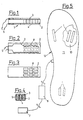
- the device 1 essentially becomes formed by an elastic flat body 2 and two conductor means 3, 4 covering these upwards and downwards, which are connected via appropriate lines 5 both to an electrical power supply 6 and to a signal transmitter 7.
- the flat body 2 made of the elastic material, for. B. a rubber or plastic (polyurethane), is provided over almost its entire extent with a series of recesses 8, and it is a conductor means as a flat circuit board 4 and the other, preferably overlying conductor means 3 as a, with knobs 9 provided conductor body 3, formed.
- the knobs 9 of this conductor body 3 dip into the lattice-shaped recesses 8 of the flat body 2 to such an extent that they do not yet touch the underlying printed circuit board 4 before loading this flat body.
- the conductor means 3, 4 can consist of a metal foil or also of a rubber-like material which is vapor-coated or provided on the surface side with an electrically conductive layer. In order to make these conductor means 3, 4 as flat as possible and still maintain their elasticity over a longer effective range, it is advisable to produce the conductor means from a plastic and to provide them with the current-conducting layer which conducts the corresponding current flow.
- the device 1 itself, consisting of the flat body 2 and the conductor means 3, 4 attached to it, is generally very flat, the strength of which is determined on the one hand by the respective threshold value and on the other hand by the pressure loads to be detected.
- this device 1 it is advisable to insert the device between the sole halves 10, 11 of an insole 12 and to design this device 1 so flat that after it has been inserted into the sole halves, these hardly cover the surface of the insole 12 protrudes. Due to this configuration of the device 1, it is possible to provide it on different areas of an insole 12, so that, for example, the area of the heel can also be detected, such as, for. B.
- the signal transmitter used for displaying the corresponding pressure load to the outside can be an acoustic or optical signal transmitter, although it is of course not excluded to also carry out a radio transmission of the measured threshold values.
- the individual devices 1 can be set to a respectively determined threshold value, which is determined by the hardness or elasticity of the flat body 2, and in such a case insoles 12 with different devices 1 can be used with respect to their threshold values, so that accordingly treatment of a patient with one and the same shoe different insoles can be worn optionally.
- the individual loads for. B. that of a foot, continuously during therapy Detect and evaluate so that the threshold values of the load can be increased as the respective body part gets better.
- the invention was here based on the example of an insole 12 for detecting the pressure loads, in particular for carrying out a partial load therapy after interventions on the lower extremity, e.g. B. after total hip endoprosthesis, fractures near the joints, etc., shown and described.
- a partial load therapy after interventions on the lower extremity, e.g. B. after total hip endoprosthesis, fractures near the joints, etc., shown and described.
- this does not exclude the use of such devices 1 in ulcer prophylaxis on the diabetic foot or for the detection of other stresses, on other parts of the body, for example the bending of a knee or arm or the detection of a pressure load in the area of the buttocks, etc.
- the early detection of the respective stress on the one hand and the control of the same during the treatment process on the other hand are guarantors for optimal treatment and should be indispensable in the treatment of various diseases.
Abstract
Description
Die Erfindung bezieht sich auf eine Vorrichtung zum Erfassen von auf Druck ansprechenden Belastungen an verschiedenen Bereichen des menschlichen Körpers, wie insb. an der Sohle eines Fußes, bestehend aus mindestens einem, dem jeweiligen Bereich zugeordneten Sensor und mindestens einem, die Druckbelastung nach außen signalisierenden Geber, wobei Sensor und Geber als elektrische Bauteile ausgeführt, sowie der Sensor als Schalter und der Geber als ein, ein akustisches oder optisches Signal gebender Sender ausgebildet sind, und welcher Sensor an dem die Druckbelastung erfassenden Bereich derart eingelegt ist, daß er eine Punkt- und/oder Flächenbelastung innerhalb des zu erfassenden Bereiches aufnimmt.The invention relates to a device for detecting pressure-sensitive loads on different areas of the human body, in particular on the sole of a foot, consisting of at least one sensor assigned to the respective area and at least one sensor that signals the pressure load to the outside , wherein the sensor and transmitter are designed as electrical components, and the sensor is designed as a switch and the transmitter as a transmitter, which emits an acoustic or optical signal, and which sensor is inserted in the area detecting the pressure load in such a way that it has a point and / or absorbs surface load within the area to be recorded.
Es ist in der Medizintechnik allgemein bekannt, nach entsprechenden Verletzungen diverser Körperteile deren Rehabilitation einzuleiten und im Rahmen der Behandlung derselben neben einer Reihe von meßbaren Ergebnissen auch die Möglichkeiten der Druckbelastung entsprechender Körperteile zu erfassen. Die Erfassung entsprechender Druckbelastungen kann auch zur Vorsorge bei einer Reihe von Erkrankungen herangezogen werden, so etwa in der Ulcus-Prophylaxe an einem diabetischem Fuß u. a. Es ist bekannt, daß bei einer derartigen Erkrankung verschiedene Stellen an der Fußsohle ihr Druckempfinden nach und nach verlieren, wodurch sich bei Fortschreiten dieser Krankheit Knochen freilegen können, die bei einem derartigen Fortschritt der Erkrankung zu Amputationen u. a. führen können.It is generally known in medical technology to initiate rehabilitation after corresponding injuries to various parts of the body and in the context of the treatment thereof in addition to a series of measurable results, also to record the possibilities of pressure loading of corresponding body parts. The detection of appropriate pressure loads can also be used to prevent a number of diseases, such as ulcer prophylaxis on a diabetic foot, among others. It is known that with such a disease, various points on the sole of the foot gradually lose their pressure sensation, as a result of which if this disease progresses, bones can be exposed, which can lead to amputations, among other things, if the disease progresses in this way.
In der orthopädischen Rehabilitation ist es vielfach erwünscht, eine kontrollierte Teilbelastungstherapie durchzuführen, so daß verschiedene Körperteile nur so lange belastet werden, wie dies, ohne Beeinträchtigung der Rehabilitation, möglich erscheint. Es ist bei dieser Behandlungsart erforderlich, sogenannte Sensibilitätsstauungen rechtzeitig zu erkennen und durch Belastung anderer Körperteile so weit zu entlasten, daß die vorher belasteten Körperteile nicht überbeansprucht werden.In orthopedic rehabilitation, it is often desirable to carry out a controlled partial exercise therapy, so that different parts of the body are loaded only as long as this appears possible without impairing the rehabilitation. With this type of treatment, it is necessary to recognize so-called sensitivity congestion in good time and to relieve it by loading other parts of the body to such an extent that the previously loaded body parts are not overstressed.
Durch die europäische Patentanmeldung 0 286 054 ist ein Schuh für derartige medizinische Zwecke bekannt geworden, bei dem in dessen Schuhsohle Sensoren, sowohl im Fersen- als auch im Ballenbereich eingelegt sind, über die entsprechende Druckbelastungen aufgenommen und nach außen über eine akustische oder optische Signalgabe angezeigt werden. Die hier verwendeten Sensoren sind großflächig ausgelegt und sie sind so in die Schuhsohle eingearbeitet, daß der auf sie drückende Fuß bei Erreichen des jeweils eingestellten Schwellenwertes die entsprechende Belastung nach außen anzeigen. Das Anzeigen der Belastung kann dabei durch akustische oder optische Signale ausgelöst werden, wodurch der jeweilige Patient schnell erkennt, daß die Belastung des betreffenden Körperteiles den für die Behandlung vorgesehenen Schwellenwert überschreitet. Eine bei dieser Vorrichtung verwendete Steuereinrichtung für das Erfassen des jeweiligen Schwellenwertes erlaubt durch Umlegen von verschiedenen Schaltern verschiedene Druckstufen einzustellen, so daß ein Meßbereich, z. B. von 10 bis 60 kp, eingestellt werden kann. Die bei dieser Vorrichtung verwendeten Sensoren für das Erfassen des Schwellenwertes der jeweiligen Druckbelastung sind in einem Silikonkautschuk eingebettet und als sogenannte Druckschalter ausgebildet, die beim Zusammenführen zweier elektrischer Leiterplatten, nach Durchdrücken des Silikonkautschuks, den elektrischen Kontakt herstellen und damit das entsprechende Signal auslösen. Zwar haben sich derartige Vorrichtungen in der Praxis sehr gut bewährt, indessen ist vielfach erwünscht, den jeweiligen Schwellenwert einfacher einstellen zu können, um entsprechend dem Fortschritt der Behandlung die entsprechenden Belastungsänderungen festzulegen.European patent application 0 286 054 has disclosed a shoe for medical purposes of this type, in which sensors, both in the heel and in the ball area, are inserted in the sole of the shoe, recorded via the corresponding pressure loads and displayed externally via an acoustic or optical signal will. The sensors used here are designed over a large area and are incorporated into the sole of the shoe in such a way that the foot pressing on them indicates the corresponding load to the outside when the set threshold value is reached. The display of the load can be triggered by acoustic or optical signals, whereby the patient quickly recognizes that the load of the concerned body part exceeds the treatment threshold. A control device used in this device for detecting the respective threshold value allows different pressure levels to be set by flipping different switches, so that a measuring range, e.g. B. from 10 to 60 kp, can be adjusted. The sensors used in this device for detecting the threshold value of the respective pressure load are embedded in a silicone rubber and are designed as so-called pressure switches which, when two electrical printed circuit boards are brought together, after the silicone rubber has been pressed through, establish the electrical contact and thus trigger the corresponding signal. Although such devices have proven themselves very well in practice, it is often desirable to be able to set the respective threshold value more easily in order to determine the corresponding changes in stress in accordance with the progress of the treatment.
Hier setzt nun die Erfindung ein, der die Aufgabe zugrunde liegt, eine Vorrichtung dahingehend weiter zu bilden, daß mit dieser exakte Schwellenwerte eingestellt werden können und entsprechend dem Fortschritt der Behandlung die einzelnen Körperteile mit zunehmenden Druckbelastungen belastet und dennoch kontrolliert bleiben können.This is where the invention comes in, which is based on the object of further developing a device in such a way that exact threshold values can be set with it and the individual body parts can be subjected to increasing pressure loads and still remain controlled in accordance with the progress of the treatment.
Gemäß der Erfindung wird diese Aufgabe bei einer Vorrichtung der eingangs genannten Art dadurch gelöst, daß der Sensor von einem gitterförmig ausgestatteten, elastischen Flachkörper und diesen sandwichartig begrenzenden Leiterkörpern besteht, von denen mindestens der eine Leiterkörper mit in die gitterförmigen Aussparungen des Flachkörpers eintauchenden Noppen ausgestattet, und der andere Leiterkörper als eine plattenförmige, an dem Flachkörper liegende Leiterplatte ausgebildet ist, und daß die Noppen des einen Leiterkörpers bei entlastetem Flachkörper mit Abstand zur Leiterplatte, bei Belastung des Flachkörpers hingegen auf die Leiterplatte zur Anlage kommen, und daß der Grad der zu erfassenden Druckbelastung am zu messenden Bereich von der Elastizität des Flachkörpers bestimmt ist, wie auch die Belastung selbst durch eine Versorgung der Leiterplatte und des Leiterkörpers mit elektrischem Strom erfaßbar und elektrisch nach außen signalisierbar ist.According to the invention, this object is achieved in a device of the type mentioned at the outset in that the sensor consists of a lattice-like, elastic flat body and these sandwich-like conductor bodies, at least one of which has a conductor body with knobs immersed in the lattice-shaped recesses of the flat body, and the other conductor body is designed as a plate-shaped circuit board lying on the flat body, and in that the knobs of one Conductor body with relieved flat body at a distance from the circuit board, when the flat body is loaded, however, come to rest on the circuit board, and that the degree of the pressure load to be recorded on the area to be measured is determined by the elasticity of the flat body, as is the load itself by supplying the Printed circuit board and the conductor body can be detected with electrical current and signaled electrically to the outside.
Durch diese Maßnahmen wird nicht nur die der Erfindung zugrunde liegende Aufgabe vorteilhaft gelöst, sondern es wird noch eine Reihe weiterer Vorteile erzielt. Durch die Anwendung des elastischen Flachkörpers als Indikator der jeweils zulässigen Druckbelastung läßt sich ein breites Band unterschiedlicher Belastungen für verschiedene Anwendungsfälle, allein durch die Wahl des jeweiligen Materials und damit der Shorehärte des betreffenden Flachkörpers, festlegen. Außerdem hat dieses Material die Eigenschaft, daß es selbst bei unterschiedlichen Temperaturen seine Elastizität beibehält, wodurch Änderungen der betreffenden Schwellenwerte nicht eintreten. Der Druck, der nun direkt auf den Flachkörper bei entsprechender Belastung desselben einwirkt, muß nicht über andere Materialien länger geführt werden, sondern wirkt direkt auf diesen Flachkörper ein, so daß die entsprechende Belastung sofort erfaßt und bei Überschreiten deren Schwellenwertes nach außen signalisiert wird. Die das Signal nach außen übermittelnden Teile sind elektrische Bauteile in Form von flächigen Platten und solchen mit Noppen versehene, die nach Art eines Schalters funktionieren und bei entsprechender Kontaktbringung das Signal auslösen. Die Leiterkörper mit Noppen, wie auch die Leiterplatten sind über Drähte an einer Stromversorgung angeschlossen und sie sind über weitere, in der Zeichnung nicht mehr dargestellte Verbindungen mit dem jeweiligen akustischen oder optischen Signalgeber verbunden was zur Folge hat, daß kaum Behinderungen für den Patienten durch die Versorgungsmittel auftreten.These measures not only advantageously achieve the object on which the invention is based, but also achieve a number of further advantages. By using the elastic flat body as an indicator of the permissible pressure load in each case, a wide range of different loads can be determined for different applications, solely through the choice of the respective material and thus the Shore hardness of the respective flat body. In addition, this material has the property that it retains its elasticity even at different temperatures, as a result of which changes in the relevant threshold values do not occur. The pressure that now acts directly on the flat body with a corresponding load does not have to be passed over other materials longer, but acts directly on this flat body, so that the corresponding load is detected immediately and is signaled to the outside when its threshold value is exceeded. The parts that transmit the signal to the outside are electrical components in the form of flat plates and those with knobs, which function like a switch and trigger the signal when they are brought into contact. The conductor body with knobs, as well as the circuit boards are connected to a power supply via wires and they are connected to the respective acoustic or optical signal transmitter via further connections, which are no longer shown in the drawing, which means that hardly any Disabilities occur for the patient through the care means.
Gemäß einer vorteilhaften Weiterbildung der Erfindung ist die Vorrichtung in einer Einlegesohle eines Schuhs integriert, und es ist diese Einlegesohle von mindestens zwei, deckungsgleich aufeinanderliegenden Sohlenflächen gebildet, wie auch die Vorrichtung zwischen diesen Sohlenflächen eingelegt ist und flächenförmig den zu erfassenden Bereich der jeweils zu messenden Druckbelastung abdeckt.According to an advantageous development of the invention, the device is integrated in an insole of a shoe, and this insole is formed by at least two sole surfaces lying congruently one on top of the other, just as the device is inserted between these sole surfaces and the area to be detected of the pressure load to be measured, which is to be covered covers.
Durch diese Ausführung der Vorrichtung lassen sich Sensoren herstellen, die sehr flach ausgeführt werden können und die zwischen Sohleflächen, beispielsweise einer Einlegesohle eingelegt sein können, wodurch sie kaum über die Fläche dieser Einlegesohlen hervorragen.This embodiment of the device makes it possible to produce sensors which can be made very flat and which can be inserted between sole surfaces, for example an insole, as a result of which they hardly protrude beyond the surface of these insoles.
Eine weitere, vorteilhafte Weiterbildung der Vorrichtung zeichnet sich dadurch aus, daß mindestens ein Sensor im Bereich der Ferse und mindestens ein weiterer Sensor im Bereich des Ballens und/oder der Zehen eines Fußes zwischen den Sohleflächen eingelegt ist.A further, advantageous development of the device is characterized in that at least one sensor is inserted in the area of the heel and at least one further sensor in the area of the ball of the foot and / or the toes of a foot between the sole surfaces.
Auf diese Weise lassen sich, beispielsweise an einer Sohle an verschiedenen Bereichen Druckbelastungen messen, so daß sowohl der sogenannte Abrollvorgang des Gehens, als auch das direkte, vollflächige Aufsetzen des Fußes erfaßt werden können.In this way, pressure loads can be measured, for example on a sole, in various areas, so that both the so-called rolling process of walking and the direct, full-surface placement of the foot can be detected.
Um möglichst viele Stellen innerhalb eines Bereichs zu erfassen, können nach einer Weiterbildung der Vorrichtung deren Sensoren flächendeckend ausgeführt sein, und es können die jeweiligen, elastischen Flachkörper annähernd in deren gesamten Ausdehnung die gitterförmige Struktur aufweisen.In order to detect as many locations as possible within an area, according to a further development of the device, the sensors thereof can be designed to cover the whole area, and the respective elastic flat bodies can have the lattice-like structure over almost their entire extent.
Weitere vorteilhafte Weiterbildungen der Erfindung können insb. den verbleibenden Unteransprüchen, für die im Rahmen des Hauptanspruches Schutz begehrt wird, entnommen werden.Further advantageous developments of the invention can be found in particular in the remaining subclaims, for which protection is sought within the scope of the main claim.
In der Zeichnung ist eine der möglichen Ausführungen einer derartigen Vorrichtung als Sensor selbst und am Beispiel dessen Anwendung bei einer Einlegesohle schematisch dargestellt. Es zeigt:
- Fig. 1 eine vergrößerte Seitenansicht auf eine Vorrichtung mit dem elastischen Flachkörper und den diesen sandwichartig begrenzenden Leiterplatte und Leiterkörper, von denen letzterer mit durch den Flachkörper dringenden Noppen ausgeführt ist,
- Fig. 2 eine Draufsicht auf die Vorrichtung nach Fig. 1, mit kreisrunden Aussparungen für die Noppen des Leiterkörpers,
- Fig. 3 eine Draufsicht auf den Flachkörper mit rechteckigen Aussparungen für entsprechende Noppen, jedoch ohne den darüber liegenden Leiterkörper,
- Fig. 4 einen Schnitt durch die Vorrichtung in der Ebene IV-IV in Fig. 1,
- Fig. 5 eine Draufsicht auf eine Einlegesohle mit den in dieser eingelegten Vorrichtungen bzw. deren Sensoren im Bereich der Ferse und des Ballens eines Fußes, nebst den den Leiterkörper und die Leiterplatte mit elektrischer Energie versorgenden Leitungen und den die Druckbelastung nach außen signalisierenden Geber.
- 1 is an enlarged side view of a device with the elastic flat body and the circuit board and conductor body delimiting it in a sandwich-like manner, of which the latter is designed with knobs penetrating through the flat body,
- 2 shows a plan view of the device according to FIG. 1, with circular recesses for the knobs of the conductor body,
- 3 shows a plan view of the flat body with rectangular cutouts for corresponding knobs, but without the conductor body lying above it,
- 4 shows a section through the device in the plane IV-IV in FIG. 1,
- Fig. 5 is a plan view of an insole with the devices inserted therein or their sensors in the area of the heel and ball of a foot, in addition to the lines supplying the conductor body and the printed circuit board with electrical energy and the transmitter signaling the pressure load to the outside.
Die Vorrichtung 1 gemäß der Erfindung wird im wesentlichen von einem elastischen Flachkörper 2 und zwei diesen nach oben und unten abdeckenden Leitermitteln 3, 4 gebildet, welche über entsprechende Leitungen 5 sowohl an einer elektrischen Energieversorgung 6 als auch einem Signalgeber 7 angeschlossen sind. Der Flachkörper 2, der aus dem elastischen Werkstoff, z. B. einem Gummi oder Kunststoff (Polyurethan), bestehen kann, ist über annähernd seine gesamte Ausdehnung mit einer Reihe von Aussparungen 8 versehen, und es ist ein Leitermittel als eine flache Leiterplatte 4 und das andere, vorzugsweise darüberliegende Leitermittel 3 als ein, mit Noppen 9 versehener Leiterkörper 3, ausgebildet. Die Noppen 9 dieses Leiterkörpers 3 tauchen in die gitterförmigen Aussparungen 8 des Flachkörpers 2 so weit ein, daß sie vor Belastung dieses Flachkörpers die darunterliegende Leiterplatte 4 noch nicht berühren. Erst bei Belastung dieses Flachkörpers 2 senken sich die einzelnen Noppen 9 in die gitterförmigen Aussparungen 8 des Flachkörpers ein und sie senken sich dabei so weit, daß sie auf die darunterliegende Leiterplatte 4 zur Anlage kommen. Durch diese Anlage der Noppen 9 auf die darunterliegende Leiterplatte 4 wird ein Kontakt geschaffen und damit ein Stromfluß ausgelöst, der zur Folge hat, daß dieser über den Signalgeber 7 die entsprechende Belastung und damit den eingestellten Schwellenwert nach außen anzeigt. Während der Flachkörper 2 aus dem elastischen Werkstoff besteht, können die Leitermittel 3, 4 aus einer Metallfolie oder auch aus einem gummiähnlichen Werkstoff bestehen, der oberflächenseitig mit einer stromleitenden Schicht bedampft bzw. versehen ist. Um diese Leitermittel 3, 4 dabei so flach wie möglich auszuführen und dennoch deren Elastizität über einen längeren Wirkungsbereich aufrecht zu erhalten, empfiehlt es sich, die Leitermittel aus einem Kunststoff herzustellen und diesen mit der stromleitenden Schicht zu versehen, die den entsprechenden Stromfluß leitet.The
Die Vorrichtung 1 selbst, bestehend aus dem Flachkörper 2 und den an diesem angebrachten Leitermitteln 3, 4 ist in der Regel sehr flach ausgeführt, wobei deren Stärke von dem jeweiligen Schwellenwert einerseits und den zu erfassenden Druckbelastungen andererseits bestimmt wird. Bei Anwendung dieser Vorrichtung 1 für die Erfassung von Druckbelastungen eines Fußes empfiehlt es sich, die Vorrichtung zwischen die Sohlenhälften 10, 11 einer Einlegesohle 12 einzubringen und diese Vorrichtung 1 so flach auszubilden, daß nach deren Einlegung in den Sohlenhälften diese kaum über die Fläche der Einlegesohle 12 ragt. Aufgrund dieser Ausgestaltung der Vorrichtung 1 ist es möglich, diese an verschiedenen Bereichen einer Einlegesohle 12 vorzusehen, so daß beispielsweise der Bereich der Ferse ebenso erfaßt werden kann, wie z. B. der Bereich des Ballens eines Fußes, wodurch sowohl Rollbewegungen des Fußes als auch abrupte, senkrechte Belastungen desselben erfaßt werden können. Der verwendete Signalgeber für das Anzeigen der entsprechenden Druckbelastung nach außen kann ein akustischer oder optischer Signalgeber sein, wobei es selbstverständlich nicht ausgeschlossen ist, auch eine Funkübertragung der gemessenen Schwellenwerte vorzunehmen.The
Die einzelnen Vorrichtungen 1 können auf einen jeweils bestimmten Schwellenwert eingestellt sein, welcher durch die Härte bzw. Elastizität des Flachkörpers 2 bestimmt wird, und es können in einem solchen Fall Einlegesohlen 12 mit unterschiedlichen Vorrichtungen 1 im Bezug auf deren Schwellenwerte verwendet werden, so daß entsprechend der Behandlung eines Patienten mit einem und dem gleichen Schuh verschiedene Einlegesohlen wahlweise, getragen werden können.The
Auf diese Weise lassen sich die einzelnen Belastungen, z. B. die eines Fußes, während einer Therapie kontinuierlich erfassen und auswerten, so daß mit zunehmender Gesundung des jeweiligen Körperteiles die Schwellenwerte der Belastung angehoben werden können.In this way, the individual loads, for. B. that of a foot, continuously during therapy Detect and evaluate so that the threshold values of the load can be increased as the respective body part gets better.
Die Erfindung wurde hier am Beispiel einer Einlegesohle 12 für das Erfassen der Druckbelastungen, insb. für die Durchführung einer Teilbelastungstherapie nach Eingriffen an der unteren Extremität, z. B. nach Totalhüftendoprothese, gelenknahen Knochenbrüchen usw, dargestellt und beschrieben. Dies schließt natürlich nicht aus, solche Vorrichtungen 1 auch in der Ulcusprophylaxe am diabetischen Fuß oder für das Erfassen anderer Belastungen, an anderer Körperteile zu verwenden, so beispielsweise der Beuge eines Knies oder Armes oder dem Erfassen einer Druckbelastung im Bereich des Gesäßes usw.The invention was here based on the example of an insole 12 for detecting the pressure loads, in particular for carrying out a partial load therapy after interventions on the lower extremity, e.g. B. after total hip endoprosthesis, fractures near the joints, etc., shown and described. Of course, this does not exclude the use of
Das Früherfassen der jeweiligen Belastung einerseits und das Kontrollieren derselben während des Behandlungsvorganges andererseits sind Mitgaranten für eine optimale Behandlung und dürften in der Behandlung diverser Erkrankungen unentbehrlich sein.The early detection of the respective stress on the one hand and the control of the same during the treatment process on the other hand are guarantors for optimal treatment and should be indispensable in the treatment of various diseases.
- 1 Vorrichtung1 device
- 2 Flachkörper2 flat bodies
- 3 Leiterkörper3 conductor bodies
- 4 Leiterkörper4 conductor bodies
- 5 Leitung5 line
- 6 Energieversorgung6 energy supply
- 7 Signalgeber7 signal transmitters
- 8 Aussparung8 recess
- 9 Noppen9 knobs
- 10 Sohlenhälften10 sole halves
- 11 Sohlenhälften11 sole halves
- 12 Einlegesohle12 insole
Claims (11)
Applications Claiming Priority (2)
| Application Number | Priority Date | Filing Date | Title |
|---|---|---|---|
| DE8910258U | 1989-08-28 | ||
| DE8910258U DE8910258U1 (en) | 1989-08-28 | 1989-08-28 |
Publications (2)
| Publication Number | Publication Date |
|---|---|
| EP0415036A2 true EP0415036A2 (en) | 1991-03-06 |
| EP0415036A3 EP0415036A3 (en) | 1991-04-17 |
Family
ID=6842340
Family Applications (1)
| Application Number | Title | Priority Date | Filing Date |
|---|---|---|---|
| EP19900113066 Withdrawn EP0415036A3 (en) | 1989-08-28 | 1990-07-09 | Pressure detecting device responsive to load at different regions of the human body, especially at the sole of a foot |
Country Status (2)
| Country | Link |
|---|---|
| EP (1) | EP0415036A3 (en) |
| DE (1) | DE8910258U1 (en) |
Cited By (11)
| Publication number | Priority date | Publication date | Assignee | Title |
|---|---|---|---|---|
| WO1994001041A1 (en) * | 1992-07-01 | 1994-01-20 | Goldman Robert J | Capacitive biofeedback sensor with resilient polyurethane dielectric |
| DE9406117U1 (en) * | 1994-04-13 | 1994-09-08 | Dekumed Ges Fuer Kunststoff Un | Shoe insert with load monitoring |
| ES2070692A2 (en) * | 1992-11-17 | 1995-06-01 | Univ Politecnica De Valencia I | Soles instrumented to measure pressures |
| US5437289A (en) * | 1992-04-02 | 1995-08-01 | Liverance; Howard L. | Interactive sports equipment teaching device |
| NL9402147A (en) * | 1994-12-16 | 1996-08-01 | Robert Leonard Krullaards | Device for determining the squeezing (muscular) strength |
| DE19751878A1 (en) * | 1997-11-22 | 1999-05-27 | Sonja Lange | Indication system for occurrence of loading on foot or leg e.g. for rehabilitation, therapy and athletic research |
| WO2003045239A1 (en) * | 2001-11-29 | 2003-06-05 | Koninklijke Philips Electronics N.V. | Shoe based force sensor and equipment for use with the same |
| FR2851428A1 (en) * | 2003-02-26 | 2004-08-27 | Ass De Promotion De L I De Pro | Instrumented sole for e.g. medial application, has housing that receives dynamometric sensor to measure pressure of support on zone of foot planting surface, and plates fixed to sensor for transmitting support pressure to sensor |
| CN104093357A (en) * | 2011-11-29 | 2014-10-08 | 李珍旭 | Shoe insole sensor for diagnosing gait, and shoe insole substrate connected thereto |
| DE102015105004B3 (en) * | 2015-03-31 | 2016-09-01 | Fraunhofer-Gesellschaft zur Förderung der angewandten Forschung e.V. | Textile material with incorporated elastomer sensors |
| CN117122326A (en) * | 2023-08-24 | 2023-11-28 | 上海市第四人民医院 | Foot muscle strength intelligent testing device, method and system |
Families Citing this family (5)
| Publication number | Priority date | Publication date | Assignee | Title |
|---|---|---|---|---|
| DE9202462U1 (en) * | 1992-02-26 | 1992-04-30 | Paromed Medizintechnik Gmbh, 8201 Neubeuern, De | |
| DE4418775C2 (en) * | 1994-05-28 | 1999-11-04 | Heinz Lammer | Device for detecting pressure loads on the sole of a patient's foot |
| DE19949653A1 (en) * | 1999-10-14 | 2001-04-19 | Robert Wagner | Re-useable alarm for progressive healing of broken bone, is placed in loading path as e.g. insole, and allows for progressive increase of load-warning threshold |
| ES2221577B1 (en) * | 2003-06-05 | 2006-02-16 | Juan Carlos Chasco Perez De Arenaza | SMART LAMINATED PRESORA SURFACE. |
| WO2006128931A1 (en) * | 2005-05-30 | 2006-12-07 | Chasco Perez De Arenaza Juan C | Sheet comprising zones that are communicated with one another |
Citations (4)
| Publication number | Priority date | Publication date | Assignee | Title |
|---|---|---|---|---|
| FR2206495A1 (en) * | 1972-11-13 | 1974-06-07 | Gradisar Ivan Albin | |
| DE3011266A1 (en) * | 1980-03-24 | 1981-10-01 | Battelle-Institut E.V., 6000 Frankfurt | Measurement mat for laminar pressure distributions - has transverse and longitudinal conductors on either side forming electrodes |
| GB2115935A (en) * | 1982-03-01 | 1983-09-14 | Lord Corp | Measuring force electrically |
| EP0286054A1 (en) * | 1987-04-08 | 1988-10-12 | AMOENA Medizin-Orthopädie-Technik GmbH | Applied load control device |
-
1989
- 1989-08-28 DE DE8910258U patent/DE8910258U1/de not_active Expired
-
1990
- 1990-07-09 EP EP19900113066 patent/EP0415036A3/en not_active Withdrawn
Patent Citations (4)
| Publication number | Priority date | Publication date | Assignee | Title |
|---|---|---|---|---|
| FR2206495A1 (en) * | 1972-11-13 | 1974-06-07 | Gradisar Ivan Albin | |
| DE3011266A1 (en) * | 1980-03-24 | 1981-10-01 | Battelle-Institut E.V., 6000 Frankfurt | Measurement mat for laminar pressure distributions - has transverse and longitudinal conductors on either side forming electrodes |
| GB2115935A (en) * | 1982-03-01 | 1983-09-14 | Lord Corp | Measuring force electrically |
| EP0286054A1 (en) * | 1987-04-08 | 1988-10-12 | AMOENA Medizin-Orthopädie-Technik GmbH | Applied load control device |
Cited By (20)
| Publication number | Priority date | Publication date | Assignee | Title |
|---|---|---|---|---|
| US5437289A (en) * | 1992-04-02 | 1995-08-01 | Liverance; Howard L. | Interactive sports equipment teaching device |
| WO1994001041A1 (en) * | 1992-07-01 | 1994-01-20 | Goldman Robert J | Capacitive biofeedback sensor with resilient polyurethane dielectric |
| US5449002A (en) * | 1992-07-01 | 1995-09-12 | Goldman; Robert J. | Capacitive biofeedback sensor with resilient polyurethane dielectric for rehabilitation |
| US5608599A (en) * | 1992-07-01 | 1997-03-04 | Goldman; Robert J. | Capacitive biofeedback sensor with resilient polyurethane dielectric for rehabilitation |
| US5662123A (en) * | 1992-07-01 | 1997-09-02 | Goldman; Robert J. | Capacitive biofeedback sensor with resilient polyurethane dielectric for rehabilitation |
| US5775332A (en) * | 1992-07-01 | 1998-07-07 | Goldman; Robert J. | Capacitive biofeedback sensor with resilient polyurethane dielectric for rehabilation |
| ES2070692A2 (en) * | 1992-11-17 | 1995-06-01 | Univ Politecnica De Valencia I | Soles instrumented to measure pressures |
| DE9406117U1 (en) * | 1994-04-13 | 1994-09-08 | Dekumed Ges Fuer Kunststoff Un | Shoe insert with load monitoring |
| NL9402147A (en) * | 1994-12-16 | 1996-08-01 | Robert Leonard Krullaards | Device for determining the squeezing (muscular) strength |
| DE19751878A1 (en) * | 1997-11-22 | 1999-05-27 | Sonja Lange | Indication system for occurrence of loading on foot or leg e.g. for rehabilitation, therapy and athletic research |
| WO2003045239A1 (en) * | 2001-11-29 | 2003-06-05 | Koninklijke Philips Electronics N.V. | Shoe based force sensor and equipment for use with the same |
| US6807869B2 (en) | 2001-11-29 | 2004-10-26 | Koninklijke Philips Electronics N.V. | Shoe based force sensor and equipment for use with the same |
| FR2851428A1 (en) * | 2003-02-26 | 2004-08-27 | Ass De Promotion De L I De Pro | Instrumented sole for e.g. medial application, has housing that receives dynamometric sensor to measure pressure of support on zone of foot planting surface, and plates fixed to sensor for transmitting support pressure to sensor |
| EP1464281A1 (en) * | 2003-02-26 | 2004-10-06 | Association De Promotion De L'institut De Productique De Franche-Comte (Apip) | Instrumented shoe sole and shoe with instrumented sole |
| CN104093357A (en) * | 2011-11-29 | 2014-10-08 | 李珍旭 | Shoe insole sensor for diagnosing gait, and shoe insole substrate connected thereto |
| CN104093357B (en) * | 2011-11-29 | 2016-05-11 | 李珍旭 | For the shoe-pad sensor of walking diagnosis and the shoe-pad substrate being in contact with it |
| DE102015105004B3 (en) * | 2015-03-31 | 2016-09-01 | Fraunhofer-Gesellschaft zur Förderung der angewandten Forschung e.V. | Textile material with incorporated elastomer sensors |
| EP3076145A1 (en) | 2015-03-31 | 2016-10-05 | Fraunhofer-Gesellschaft zur Förderung der angewandten Forschung e.V. | Textile material with incorporated elastomer sensors |
| CN117122326A (en) * | 2023-08-24 | 2023-11-28 | 上海市第四人民医院 | Foot muscle strength intelligent testing device, method and system |
| CN117122326B (en) * | 2023-08-24 | 2024-02-20 | 上海市第四人民医院 | Foot muscle strength intelligent testing device, method and system |
Also Published As
| Publication number | Publication date |
|---|---|
| DE8910258U1 (en) | 1989-10-12 |
| EP0415036A3 (en) | 1991-04-17 |
Similar Documents
| Publication | Publication Date | Title |
|---|---|---|
| EP0415036A2 (en) | Pressure detecting device responsive to load at different regions of the human body, especially at the sole of a foot | |
| EP3270841B1 (en) | Textile fabric for placing on the skin and/or a wound of a patient, and transdermal patch and arrangement consisting of a transdermal patch and an evaluation unit | |
| DE3930451C2 (en) | Device for high-frequency coagulation of biological tissue | |
| DE2656864C3 (en) | Device for detecting the weight load on a foot | |
| EP3348185B1 (en) | Device for preventing excessive loads on the human foot during walking and method for the operation thereof | |
| DE3906071C2 (en) | ||
| EP2525746B1 (en) | Liner with integrated electrode | |
| DE8205363U1 (en) | Neutral electrode for high frequency surgery | |
| DE202014105408U1 (en) | Device for the diagnosis of circulatory disorders and developing inflammation in the feet of patients with diabetes | |
| DE102014008091A1 (en) | Device for detecting pressure loads and / or temperature differences for the diabetic foot | |
| EP2033575B1 (en) | Method for continuously or step by step manufacturing of biomedical multiple electrodes for single use, and matrix electrode system consisting of same | |
| DE3631923A1 (en) | Device for measuring compressive forces | |
| EP3020298A1 (en) | Device for diagnosing circulation disorders and inflammation in the feet of diabetes patients | |
| DE3732891A1 (en) | Shoe with measurement device | |
| DE2848396A1 (en) | Broken leg member protection system during healing - measures force between foot and ground when walking and emits warning signal | |
| DE3743835C1 (en) | Limit-load annunciator for detecting weight loading in shoes | |
| DE4308945A1 (en) | Shoe insert for ulcer prophylaxis for diabetic foot - has hydrocell with pressure sensor connected to liquid in cell which activates warning signal if adjustable max. pressure threshold is exceeded | |
| DE202016008231U1 (en) | Ladder unit of an insole for recording biophysical parameters in shoes with sensors | |
| DE102014103441B4 (en) | Force plate | |
| EP2877091A1 (en) | Device for sensing the size of a load on a biological system | |
| DE4418775C2 (en) | Device for detecting pressure loads on the sole of a patient's foot | |
| WO2016116100A1 (en) | Training apparatus for improving force, mobility, endurance and control at the level of various joints and the soft tissue structures surrounding them | |
| DE10038446A1 (en) | Insole for control of rehabilitation, after foot surgery, has sensors which are activated on breaching given load thresholds, to generate an acoustic signal or distort to give a sensation | |
| DE10247404A1 (en) | Sensor for detecting force magnitude and direction for pressure measurement has conducting track structure of concentric track sectors, pressure transfer layer, rigid pressure distribution body | |
| WO2023051879A1 (en) | Insole and foot pressure measuring arrangement |
Legal Events
| Date | Code | Title | Description |
|---|---|---|---|
| PUAI | Public reference made under article 153(3) epc to a published international application that has entered the european phase |
Free format text: ORIGINAL CODE: 0009012 |
|
| PUAL | Search report despatched |
Free format text: ORIGINAL CODE: 0009013 |
|
| AK | Designated contracting states |
Kind code of ref document: A2 Designated state(s): AT BE CH DE DK ES FR GB GR IT LI LU NL SE |
|
| RHK1 | Main classification (correction) |
Ipc: A61B 5/103 |
|
| STAA | Information on the status of an ep patent application or granted ep patent |
Free format text: STATUS: THE APPLICATION HAS BEEN WITHDRAWN |
|
| AK | Designated contracting states |
Kind code of ref document: A3 Designated state(s): AT BE CH DE DK ES FR GB GR IT LI LU NL SE |
|
| 18W | Application withdrawn |
Withdrawal date: 19910409 |
|
| R18W | Application withdrawn (corrected) |
Effective date: 19910409 |