EP0414344B1 - Marine seismic reflection geophysical surveying - Google Patents
Marine seismic reflection geophysical surveying Download PDFInfo
- Publication number
- EP0414344B1 EP0414344B1 EP90306104A EP90306104A EP0414344B1 EP 0414344 B1 EP0414344 B1 EP 0414344B1 EP 90306104 A EP90306104 A EP 90306104A EP 90306104 A EP90306104 A EP 90306104A EP 0414344 B1 EP0414344 B1 EP 0414344B1
- Authority
- EP
- European Patent Office
- Prior art keywords
- water
- pressure
- velocity
- wave
- seismic
- Prior art date
- Legal status (The legal status is an assumption and is not a legal conclusion. Google has not performed a legal analysis and makes no representation as to the accuracy of the status listed.)
- Expired - Lifetime
Links
- XLYOFNOQVPJJNP-UHFFFAOYSA-N water Substances O XLYOFNOQVPJJNP-UHFFFAOYSA-N 0.000 claims description 158
- 238000000034 method Methods 0.000 claims description 36
- 239000000463 material Substances 0.000 claims description 22
- 230000026683 transduction Effects 0.000 claims description 14
- 238000010361 transduction Methods 0.000 claims description 14
- 239000007787 solid Substances 0.000 claims description 13
- 238000012937 correction Methods 0.000 claims description 9
- 230000001419 dependent effect Effects 0.000 claims description 7
- 239000000126 substance Substances 0.000 claims description 3
- 238000001028 reflection method Methods 0.000 claims description 2
- 239000002245 particle Substances 0.000 description 32
- 230000014509 gene expression Effects 0.000 description 12
- NCGICGYLBXGBGN-UHFFFAOYSA-N 3-morpholin-4-yl-1-oxa-3-azonia-2-azanidacyclopent-3-en-5-imine;hydrochloride Chemical compound Cl.[N-]1OC(=N)C=[N+]1N1CCOCC1 NCGICGYLBXGBGN-UHFFFAOYSA-N 0.000 description 9
- 230000001427 coherent effect Effects 0.000 description 7
- 230000004044 response Effects 0.000 description 7
- 230000001902 propagating effect Effects 0.000 description 5
- 238000005311 autocorrelation function Methods 0.000 description 4
- 230000005540 biological transmission Effects 0.000 description 4
- 238000004458 analytical method Methods 0.000 description 3
- 238000003491 array Methods 0.000 description 3
- 230000015572 biosynthetic process Effects 0.000 description 3
- 230000000694 effects Effects 0.000 description 3
- 238000005755 formation reaction Methods 0.000 description 3
- 238000012545 processing Methods 0.000 description 3
- 238000001228 spectrum Methods 0.000 description 3
- 230000001133 acceleration Effects 0.000 description 2
- 230000006835 compression Effects 0.000 description 2
- 238000007906 compression Methods 0.000 description 2
- 238000013480 data collection Methods 0.000 description 2
- 238000006073 displacement reaction Methods 0.000 description 2
- 238000001914 filtration Methods 0.000 description 2
- 238000001615 p wave Methods 0.000 description 2
- 238000007619 statistical method Methods 0.000 description 2
- 230000003321 amplification Effects 0.000 description 1
- 238000010420 art technique Methods 0.000 description 1
- ROJMAHHOFDIQTI-UHFFFAOYSA-L calcium;2-[2-[bis(carboxylatomethyl)amino]ethyl-(carboxylatomethyl)amino]acetate;hydron;piperazine Chemical compound [Ca+2].C1CNCCN1.OC(=O)CN(CC([O-])=O)CCN(CC(O)=O)CC([O-])=O ROJMAHHOFDIQTI-UHFFFAOYSA-L 0.000 description 1
- 238000004364 calculation method Methods 0.000 description 1
- 238000009795 derivation Methods 0.000 description 1
- 239000002360 explosive Substances 0.000 description 1
- 238000005259 measurement Methods 0.000 description 1
- ORQBXQOJMQIAOY-UHFFFAOYSA-N nobelium Chemical compound [No] ORQBXQOJMQIAOY-UHFFFAOYSA-N 0.000 description 1
- 238000003199 nucleic acid amplification method Methods 0.000 description 1
- 230000000704 physical effect Effects 0.000 description 1
- 238000012797 qualification Methods 0.000 description 1
- 230000005855 radiation Effects 0.000 description 1
- 238000011084 recovery Methods 0.000 description 1
- 238000002310 reflectometry Methods 0.000 description 1
- 230000004043 responsiveness Effects 0.000 description 1
- 239000011343 solid material Substances 0.000 description 1
- 238000006467 substitution reaction Methods 0.000 description 1
Images


Classifications
-
- G—PHYSICS
- G01—MEASURING; TESTING
- G01V—GEOPHYSICS; GRAVITATIONAL MEASUREMENTS; DETECTING MASSES OR OBJECTS; TAGS
- G01V1/00—Seismology; Seismic or acoustic prospecting or detecting
- G01V1/28—Processing seismic data, e.g. for interpretation or for event detection
- G01V1/36—Effecting static or dynamic corrections on records, e.g. correcting spread; Correlating seismic signals; Eliminating effects of unwanted energy
- G01V1/364—Seismic filtering
-
- G—PHYSICS
- G01—MEASURING; TESTING
- G01V—GEOPHYSICS; GRAVITATIONAL MEASUREMENTS; DETECTING MASSES OR OBJECTS; TAGS
- G01V1/00—Seismology; Seismic or acoustic prospecting or detecting
- G01V1/38—Seismology; Seismic or acoustic prospecting or detecting specially adapted for water-covered areas
- G01V1/3808—Seismic data acquisition, e.g. survey design
-
- G—PHYSICS
- G01—MEASURING; TESTING
- G01V—GEOPHYSICS; GRAVITATIONAL MEASUREMENTS; DETECTING MASSES OR OBJECTS; TAGS
- G01V2210/00—Details of seismic processing or analysis
- G01V2210/50—Corrections or adjustments related to wave propagation
- G01V2210/56—De-ghosting; Reverberation compensation
Definitions
- This invention relates to marine seismic surveying and, more particularly, to a seismic reflection method of geophysical prospecting.
- marine seismic surveys are conducted by towing an energy source and seismic detectors behind a vessel.
- the source imparts an acoustic wave to the water, creating a wavefield which travels coherently into the underlying earth.
- the wavefield strikes interfaces between earth formations, or strata, it is reflected back through the earth and water to the detectors, where it is converted to electrical signals and recorded.
- electrical signals Through analysis of these signals, it is possible to determine the shape, position and lithology of the sub-bottom formations.
- VSP vertical seismic profiling
- a seismic wave generated in (or reflected off) earth strata passes into the water in a generally upward direction.
- This wave termed the "primary” travels through the water and past the seismic detector which records its presence.
- the wavefield continues upward to the water's surface, where it is reflected back downwards.
- This reflected, or “ghost”, wavefield also travels through the water and past the detector, where it is again recorded.
- the ghost wavefield may itself be reflected upwards through the water, giving rise to a series of one or more subsequent ghost reflections.
- This reverberation of the seismic wavefield in the water obscures seismic data, amplifying certain frequencies and attenuating others, thereby making it difficult to analyze the underlying earth formations.
- Ruehle United States Patent No. 4,486,865 discloses a technique for reducing ghosting wherein a pressure detector and a particle velocity detector are positioned in close proximity to one another in the water. The output of at least one of the detectors is gain-adjusted and filtered, using a deconvolution operation having a predetermined amount of white noise to the zero lag of the autocorrelation function. The patent suggests that, by adding this deconvolved/gain-adjusted signal to the output of the other detector, ghost reflections may be cancelled.
- Berni, United States Patent No. 4,345,473 suggests the use of a vertical component accelerometer in combination with a hydrophone for cancelling surface-reflected noise in marine seismic operations.
- Gal'perin "Vertical Seismic Profiling", Special Publication No. 12 of the Society of Exploration Geophysicists, suggests the use of a seismic detector which combines the output of a pressure and velocity sensor for use in VSP surveying.
- EP-A-0089700 refers to a marine seismic method (and system) which reduces the effect of surface reflection, employing a sensing of both the pressure waves and the motion of the water particles.
- US-A-4752916 describes a method (and system) for removing the effect of the source wavelet from seismic data measuring both the pressure field and the particle velocity.
- an object of this invention is to provide an improved system for marine seismic reflection prospecting, especially (but not exclusively) for marine seismic prospecting capable of attenuating coherent noise resulting, for example, from water column reverberation.
- the coherent noise is reduced by applying a scale factor to the output of a pressure transducer and a particle velocity transducer positioned substantially adjacent one another in the water.
- the transducers can be positioned at a point in the water above the bottom and, thereby, eliminate downgoing components of reverberation, or they can be positioned at the bottom of the water and thereby eliminate both upgoing and downgoing components of the reverberation.
- the scale factor which derives from the acoustical impedance of the water or water-bottom material, can be determined both deterministically and statistically.
- the former involves measuring and comparing the responses of the pressure and velocity transducers to a pressure wave induced in the water.
- the latter involves comparing the magnitude of the pressure signal autocorrelation to the pressure and velocity signal crosscorrelation at selected lag values or, alternatively, comparing the magnitude of the pressure signal autocorrelation to the velocity signal autocorrelation at selected lag values.
- the water velocity-representative and water pressure-representative signals can be scaled by multiplying at least a selected one of them by a scale factor dependent upon an acoustical impedance of the water.
- the scaled signals are then summed to produce the so-called enhanced seismic reflection signal.
- this scale factor can be expressed as ( ⁇ ′ ⁇ ′/Dir corr )*(G p /G v ), where ⁇ ′ is a density of the water; ⁇ ′ is a velocity of propagation of the seismic wave in the water; G p is a transduction constant associated with the water pressure detecting step (e.g. a transduction constant of the transducer with which the water pressure is recorded); G v is a transduction constant associated with the water velocity detecting step (e.g. a transduction constant of the transducer with which the particle velocity is detected); and Dir corr is a directivity correction factor associated with an angle of propagation of the seismic wave in the water.
- the directivity correction factor, Dir corr is expressed as a function of ⁇ p ′, the angle of propagation from vertical of the seismic wave in the water.
- Dir corr is equal to cos( ⁇ p ′) for ⁇ p ′ less than a selected critical angle and, otherwise, is equal to 1.
- the critical angle is a function of the propagation velocity of the seismic wave and is substantially equal to arcsin( ⁇ ′/ ⁇ ); where ( ⁇ ′) is the velocity of propagation of the seismic wave in the water and ( ⁇ ) is a velocity of propagation of the seismic wave in an earth material at said water's bottom.
- the invention provides a method for seismic reflection prospecting in water covered areas in which the water pressure and particle velocity signals are generated by detectors placed on, or substantially near, the water's bottom.
- the pressure and velocity measured by those detectors can be scaled and summed to produce an enhanced seismic reflection signal.
- the scale factor depends upon an acoustical impedance of a solid earth material at the water's bottom and is defined by the term ( ⁇ /Dir corr )*(G p /G v ), where ( ⁇ ) is the density of the earth material at the water's bottom; ( ⁇ ) is the propagation velocity of the seismic wave in that earth material; and Dir corr , G p and G v are defined as above.
- the aforementioned scale factor can be determined statistically or deterministically.
- the former involves determining the ratio of a selected lag of the autocorrelation of the water pressure to a selected lag of crosscorrelation of the water pressure and water velocity at selected lag values or, preferrably, determining the ratio of a selected lag of the autocorrelation of the water pressure to a selected lag of the water velocity.
- the selected lags can correspond, for example, to a time of two-way travel of seismic wave through said water between the position at which the pressure and velocity detectors reside and the water's surface. Preferably, however, the selected lag is zero.
- Derivation of the scale factor deterministically involves generating a pressure wave from a position above the sensor point (i.e. the point at which the pressure and particle velocity readings are taken during seismic data collection).
- the scale factor can then be derived from the ratio of the absolute values of the pressure and particle velocity magnitudes at the sensor point during selected arrivals, e.g. the first arrival of that pressure wave.
- Figure 1 depicts a preferred marine seismic reflection prospecting system constructed in accord with the invention and having a hydrophone/geophone sensor pair disposed above the water bottom.
- a marine craft 14 tows a seismic source 16 and streamer 18 through a body of water 10, e.g., a lake or ocean, overlying a portion of the earth's surface 12 to be studied.
- the source 16 is preferably an acoustic energy source, e.g., an explosive device or compressed air gun, constructed and operated in a manner conventional to the art.
- Illustrated streamer 18 includes sensor 22, including a hydrophone for detecting water pressure and a geophone for detecting water particle velocity.
- the streamer 18 and its accompanying hydrophone/geophone pair 22 are constructed and operated in a manner conventional to the art. In this regard, it will be appreciated, for example, that whereas only one sensor 22 is shown, in practice the streamer 18 could include a plurality of such units.
- the streamer 18 and hydrophone/geophone pair 22 are positioned on the water's bottom.
- Such an arrangement is ideal for use in three dimensional "bottom-cable" operations, where a long cable with sensors is deployed on the bottom 12, and a set of parallel lines, or swath, is shot with an airgun source 16.
- the bottom cable 18 is retrieved and redeployed in a line displaced from, but parallel to, the previous location. There, another swath of shot lines is shot.
- a separate electrical signal is sent to the recording system for each hydrophone and each geophone spatial array.
- the marine vessel 14 fires source 16 at predetermined locations while the signals from the hydrophone and geophone arrays are recorded. These data are referred to as reflection data.
- the shooting vessel 14 makes one traverse directly over the cable 18, shooting the marine seismic source 16 directly over each spatial array of hydrophones and geophones, e.g., pair 22, or as close thereto as practical.
- the resulting signals from the two arrays directly below the source are recorded. These data are referred to as calibration data.
- the recorded hydrophone and geophone reflection data are demultiplexed, gain-removed and amplitude recovered using identical amplitude recovery curves.
- the gain-removal process properly uses the K-gain settings of the recording instruments.
- the calibration data are also demultiplexed and gain-removed.
- the gain-removal process properly uses the K-gain settings of the recording instruments.
- the particle velocity component of the geophone reflection and calibration data are then multiplicatively scaled by a factor (G p /G v )( ⁇ ′)( ⁇ ′) where
- the illustrated system uses a filter designed in accord with the theoretical or measured impulse responses of the hydrophones and geophones to convert the phase spectrum and normalized amplitude spectrum of the geophone to match that of the hydrophone, or vice versa.
- This filter is applied to every trace of the reflection and calibration geophone data or the hydrophone data subsequent to scaling.
- a scale factor K is determined from the calibration data for each receiver station (i) by dividing the hydrophone first-arrival peak amplitude by the geophone first-arrival peak amplitude and taking the absolute value of the resultant value. Then, for each pair of traces recorded at receiver location (i), the geophone trace is multiplied by a factor K (not to be confused with the "K-gain" of the transducers) and added to the hydrophone trace.
- the resulting data are then processed in the manner conventional to the art for water-bottom cable data.
- the factor K is calculated as the absolute value of the geophone first-arrival peak divided by the hydrophone first-arrival peak.
- K is multiplied by the hydrophone trace prior to adding it to the geophone trace.
- the factor K is determined as follows. Geophone traces are multiplied by a range of potential, or candidate, factors, K, and added to their respective hydrophone traces. The resulting data is then stacked. Autocorrelation functions and amplitude spectra of the stacked data sets are computed and displayed. By iteratively performing these steps, an optimal value of K can be determined which minimizes the effects of the water-column reverberations.
- seismic waves generated by seismic source 16 travel downward, as indicated by rays 30 and are reflected off earth strata 26, 28 or, more particularly, off the interface 36 between those strata.
- the upwardly reflected waves 32 travel past the area occupied by the streamer 18 to the water's surface 38.
- passing the waves 32 are detected by the sensor 22 which generates electrical signals representative of pressure and particle velocity changes inherent to the wavefield and transmit those signals back to the vessel 14 for recording and processing.
- FIG. 2 outlines a preferred operating sequence for a marine seismic reflection system of the type shown in Figure 1.
- seismic source 16 generates an acoustic wave for transmission through the water and reflection from earth strata 26, 28.
- Wavefields representing primary and ghost reflections, as well as those coherent noise, travel through the water and past the streamers, where they are detected by hydrophone/geophone pair 22, step 42.
- the pair generates a water pressure-representative signal and a particle velocity-representative signal for recording and processing according to the teachings provided herein.
- the hydrophone/geophone pair 22 may be positioned anywhere in the water and, preferably, on or near the water's bottom 12.
- the system In steps 44 and 46, the system generates an enhanced seismic reflection signal representing a selected linear combination of the water pressure and the water velocity.
- this enhanced seismic reflection signal is characterized as being substantially free of at least downwardly-propagating components of reverberation of said seismic wave within the water.
- the enhanced seismic reflection signal is characterized as being substantially free of both upwardly and downwardly propagating components of reverberation.
- step 44 the system scales the water pressure-representative signal and the particle velocity-representative signal by multiplying at least one of them by a scale factor dependent on
- the system executes step 44 by multiplying the recorded particle velocity function by a scale factor as derived below and by multiplying the measured pressure function by one.
- a scale factor, determined in step 48, for use in conjunction with a hydrophone/geophone pair positioned at a point in the water above the bottom is ( ⁇ ′ ⁇ ′/Dir corr )*(G p /G v )
- ⁇ ′ is a density of the water
- ⁇ ′ is a velocity of propagation of the seismic wave in the water
- G p is a transduction constant associated with the water pressure detecting step (e.g., a transduction constant of the transducer with which the water pressure is recorded)
- G v is a transduction constant associated with the water velocity detecting step (e.g., a transduction constant of the transducer with which the particle velocity is detected)
- Dir corr is a directivity correction factor associated with an angle of propagation of the seismic wave in the water.
- the aforementioned directivity correction factor, Dir corr is expressed as a function of ⁇ p ′, the angle of propagation from vertical of the seismic wave in the water.
- Dir corr is equal to cos( ⁇ p ′) for ⁇ p ′ less than a selected critical angle and, otherwise, is equal to 1.
- the critical angle is a function of the propagation velocity of the seismic wave and can be substantially equal to arcsin( ⁇ ′/ ⁇ ), where ( ⁇ ′) is the velocity of propagation of the seismic wave in the water and ( ⁇ ) is a velocity of propagation of the seismic wave in an earth material at said water's bottom.
- step 50 the system determines the critical angle. As indicated above, this angle is determined by computing arcsin( ⁇ ′/ ⁇ ).
- a preferred scale factor for use in conjunction with a hydrophone/geophone pair positioned at the water bottom is ( ⁇ /Dir corr )*(G p /G v ) where ( ⁇ ) is the density of the earth material at the water's bottom; ( ⁇ ) is the propagation velocity of the seismic wave in that earth material; and Dir corr , G p and G v are defined as above.
- Figure 14 depicts a preferred configuration of elements in a system constructed in accord with the invention and operating with the method shown in Figure 2.
- the system 88 includes stores 90 and 92 for retaining pressure-representative and particle velocity-representative signals generated by hydrophone/geophone pair 22.
- Element 94 scales the pressure and/or velocity signal as described above in conjunction with step 44 ( Figure 2).
- Element 96 sums the scaled pressure and velocity signal as discussed above in conjunction with step 46 ( Figure 2).
- the system 88 further includes element 98 for determining a directivity correction factor as discussed above in conjunction with steps 50 and 52. That correction factor is multiplied, in accord with the teachings provided herein, as indicated over the data flow path indicator connecting elements 98 and 94.
- System 88 further includes element 100 for determining a scale factor in the manner discussed above in conjunction with step 48, above.
- An apparatus constructed in accord with Figure 14 and operating according to the method of Figure 2 can be implemented in special purpose hardware using implementation techniques conventional to the art. Preferably, however, such apparatus is implemented on a general purpose digital data processor having conventional seismic data processing software tools.
- One preferred package of software tools is commercially available from the assignee hereof under the mark "TIPEX.”
- the ray marked p zz indicates the stress (pressure) acting in the outward direction from the cube 60 and in the direction of the z-axis 62.
- F z ( ⁇ p zz / ⁇ z) ⁇ x ⁇ y ⁇ z
- Figure 4 depicts a simplified physical model of the environment in which the invention is practiced. More particularly, the illustration shows the air 66, water 10 and solid earth material 26 below the water bottom 12. Hydrophone/geophone pair 22 is shown in the water at a point above the water bottom 12. For purposes of the immediate discussion, it is assumed that plane waves vary in the direction of the x-axis 64 and the z-axis 62, but not in the direction of the y-axis.
- the water 10 depth is equal to (d) and the detector 22 is z d meters above the water bottom.
- p d ⁇ (t-(z/ ⁇ ))
- the pressure field on the water side of the interface must equal that on the solid side, at that instant of time. Accordingly, the amplitude of the transmitted pressure wave in the water is equal to 1+R′.
- an upward traveling pressure wave will continue until it encounters the air/water interface (i.e., the interface between the water 10 and the air 66).
- This interface has a reflection coefficient equal to -1. Accordingly, the pressure wave is reflected downward, in its entirety, and its sign is changed, i.e. from a compression pulse to a rarefaction pulse.
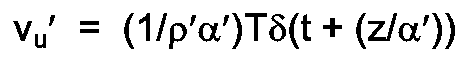
- v d ′ (T/ ⁇ ′ ⁇ ′) ⁇ (t-((2d-z)/ ⁇ ′))
- a marine prospecting system of the type depicted in Figure 1 and constructed in accord with one preferred practice of the invention, where the detectors 22 are positioned above the water's bottom, can eliminate downwardly travelling components of coherent reverberations if the pressure function is added to the velocity function, where the later is scaled by ⁇ ′ ⁇ ′.
- K ⁇ ′ ⁇ ′((1+R)/(1-R))
- K ⁇ ′ ⁇ ′( ⁇ + ⁇ ′ ⁇ ′+ ⁇ - ⁇ ′ ⁇ ′)/( ⁇ + ⁇ ′ ⁇ ′- ⁇ + ⁇ ′ ⁇ ′)
- K ⁇
- K depends on the acoustic impedance of the water-bottom material
- a system constructed in accord with the invention must consider K to be a variable from survey area to survey area, and probably for each received group within a survey area.
- Figure 7 depicts a preferred processing sequence for determining the aforementioned scale factor deterministically and statistically.
- steps 70, 72 and 74 indicate a decision to determine the scale factor by one or both methods. While the deterministic method, which requires the sounding and measurement of transducer responsiveness, is preferred, the statistical method based on ratios of the pressure and particle velocity autocorrelations and crosscorrelations can also be used. Those skilled in the art will appreciate, of course, that both methods can be used in combination.
- a marine seismic reflection system constructed in accord with the invention computes the autocorrelation of the pressure at a selected lag; see step 76.
- the system also computes the autocorrelation of the velocity at a selected lag; see step 77.
- the system computes the crosscorrelation of the pressure and particle velocity at a selected lag to wit, the two-way travel time of the seismic wave in the water column; see step 78.
- the lags for the computations of steps 76 and 77 are zero.
- the lags for this combination can also be equal to the two-way travel time of the seismic wave between the sensor 22 and the water surface.
- the system preferably divides the pressure autocorrelation by the velocity autocorrelation or, alternatively, the system divides the pressure autocorrelation by the pressure-velocity crosscorrelation.
- K ( ⁇ pp (0)/ ⁇ vv (0))
- the ratio of the pressure wave autocorrelation to the velocity wave autocorrelation at a lag equal to the two-way travel time of the seismic wave in the water column may be expressed mathematically as follows.
- ⁇ pp ( ⁇ 2d/ ⁇ ′) T2 ⁇ -(1+R)-R(1+R)2-R3(1+R)2-... ⁇
- ⁇ vv ( ⁇ 2d/ ⁇ ′) T2 ⁇ (1-R)-R(1-R)2-R3(1-R)2-... ⁇
- - ⁇ pp ( ⁇ 2d/ ⁇ ′) ⁇ vv ( ⁇ 2d/ ⁇ ′) (1+R)+R(1+R)2+R3(1+R)2+...
- a seismic energy source 16 is used to generate a pressure wave at a point disposed directly above the location of the sensor 22 in the water; see step 82.
- the output of the pressure and particle velocity detectors of the sensor 22 are then measured at a selected arrival of the resulting pressure wave; see step 84.
- a ratio of this measured pressure signal to the particle velocity signal is then used as the aforementioned scale factor; see step 86.
- Figure 15 depicts a preferred configuration of elements 102 used for determining a scale factor in a system constructed and operated in accord with the invention.
- the illustrated configuration 102 includes element 102 for routing data and controlling the other scale factor-determining elements, e.g., elements 104-120.
- Illustrated element 104 selectively determines an autocorrelation of the particle velocity signal.
- Element 106 selectively determines a crosscorrelation of the pressure and particle velocity signals, while element 108 selectively determines an autocorrelation of the pressure signal.
- the output of the autocorrelation and crosscorrelation elements 104-108 is routed through multiplexor 110 which selectively routes the appropriate values to element 112 for ratio calculations.
- the illustrated apparatus 102 includes elements 114 and 116 for identifying a selected arrival of the pressure wave, as described above in conjunction with step 84 ( Figure 7).
- the apparatus also includes element 120 for determining a ratio of the arrival-representative signal, as described above in conjunction with step 86 ( Figure 7).
- An apparatus constructed in accord with Figure 15 and operating according to the method of Figure 7 can be implemented in special purpose hardware using implementation techniques conventional to the art. Preferably, however, such apparatus is implemented on a general purpose digital data processor having conventional seismic data processing software tools.
- One preferred package of software tools is commercially available from the assignee hereof under the mark "TIPEX.”
- Figure 8 depicts the environment of Figure 4 in a manner required to permit analysis of the more complicated case of a p-wave reflection A1 arriving at the water-bottom at angle-of-incidence ⁇ p from vertical.
- rays marked with the letter A denote p-waves
- those marked with the letter B denote s-waves.
- scalar and vector displacement potential functions can be derived as solutions to the elastic wave equation, subject to the boundary conditions imposed by the model of Figure 8. From these potential functions, the pressure and particle velocity waves which will strike detectors 22 can be determined.
- v′/p′ cos ⁇ p ′/ ⁇ ′ ⁇ ′ which corresponds to the ratio of the amplitudes of the first arrivals in Figure 5.
- the additional cosine factor accounts for the directivity of the velocity detector.
- p′ and v′ each represent a wave traveling in the - ⁇ direction (upward) and the second term a wave traveling in the + ⁇ direction (downward). It will also be noted that they are again frequency domain representations of Dirac delta functions.
- K R depends upon the water-bottom material and the angle of incidence as follows:
- the scale factor required for v(t) involves the reflection coefficient of the water-bottom, and, therefore, its acoustic impedance. Methods for determining that scale factor are discussed in detail above.
Landscapes
- Life Sciences & Earth Sciences (AREA)
- Physics & Mathematics (AREA)
- Engineering & Computer Science (AREA)
- Remote Sensing (AREA)
- Geology (AREA)
- Environmental & Geological Engineering (AREA)
- Acoustics & Sound (AREA)
- General Life Sciences & Earth Sciences (AREA)
- General Physics & Mathematics (AREA)
- Geophysics (AREA)
- Oceanography (AREA)
- Geophysics And Detection Of Objects (AREA)
- Investigating Or Analyzing Materials By The Use Of Ultrasonic Waves (AREA)
Description
- This invention relates to marine seismic surveying and, more particularly, to a seismic reflection method of geophysical prospecting.
- Generally speaking, marine seismic surveys are conducted by towing an energy source and seismic detectors behind a vessel. The source imparts an acoustic wave to the water, creating a wavefield which travels coherently into the underlying earth. As the wavefield strikes interfaces between earth formations, or strata, it is reflected back through the earth and water to the detectors, where it is converted to electrical signals and recorded. Through analysis of these signals, it is possible to determine the shape, position and lithology of the sub-bottom formations.
- A problem encountered in marine surveying as well as in inverse vertical seismic profiling, or "VSP", is that of water column reverberation. The problem, which arises as a result of the inherent reflectivity of the water surface and bottom, may be explained as follows.
- A seismic wave generated in (or reflected off) earth strata passes into the water in a generally upward direction. This wave, termed the "primary", travels through the water and past the seismic detector which records its presence. The wavefield continues upward to the water's surface, where it is reflected back downwards. This reflected, or "ghost", wavefield also travels through the water and past the detector, where it is again recorded. Depending upon the nature of the earth material at the water's bottom, the ghost wavefield may itself be reflected upwards through the water, giving rise to a series of one or more subsequent ghost reflections.
- This reverberation of the seismic wavefield in the water obscures seismic data, amplifying certain frequencies and attenuating others, thereby making it difficult to analyze the underlying earth formations.
- In instances where the earth material at the water bottom is particularly hard, excess acoustic energy or noise generated by the seismic source can also become trapped in the water column, reverberating in the same manner as the reflected seismic waves themselves. This noise is often high in amplitude and, as a result, tends to cover the weaker seismic reflection signals sought for study.
- In the art, Ruehle, United States Patent No. 4,486,865, discloses a technique for reducing ghosting wherein a pressure detector and a particle velocity detector are positioned in close proximity to one another in the water. The output of at least one of the detectors is gain-adjusted and filtered, using a deconvolution operation having a predetermined amount of white noise to the zero lag of the autocorrelation function. The patent suggests that, by adding this deconvolved/gain-adjusted signal to the output of the other detector, ghost reflections may be cancelled.
- Haggerty, United States Patent No. 2,757,356, discloses a marine seismic reflection surveying system in which two seismometer spreads are disposed at two distinct depths in the water such that water column reverberations received by them are 180 degrees out of phase. By combining the output of the detectors, the patent suggests that the reverberations will cancel.
- Berni, United States Patent No. 4,345,473, suggests the use of a vertical component accelerometer in combination with a hydrophone for cancelling surface-reflected noise in marine seismic operations.
- Gal'perin, "Vertical Seismic Profiling", Special Publication No. 12 of the Society of Exploration Geophysicists, suggests the use of a seismic detector which combines the output of a pressure and velocity sensor for use in VSP surveying.
- EP-A-0089700 refers to a marine seismic method (and system) which reduces the effect of surface reflection, employing a sensing of both the pressure waves and the motion of the water particles.
- US-A-4752916 describes a method (and system) for removing the effect of the source wavelet from seismic data measuring both the pressure field and the particle velocity.
- While the aforementioned prior art techniques may be effective under certain circumstances, none is considered adequate for use in water-bottom cable surveying in deep water operations, i.e., surveys in depths greater than 15.2 to 30.5 m (50 - 100 feet). Moreover, techniques of the type proposed in the Ruehle patent suffer losses in signal quality inherent to the filtering process, for example, amplification of noise in certain frequencies.
- Accordingly, an object of this invention is to provide an improved system for marine seismic reflection prospecting, especially (but not exclusively) for marine seismic prospecting capable of attenuating coherent noise resulting, for example, from water column reverberation.
- According to the present invention, there is provided a method of geophysical prospecting in water covered areas, comprising the steps of:
- A. generating a seismic wave for reflection from earth strata;
- B. detecting water pressure at a first position in the water resulting from said seismic wave and generating a signal representative thereof;
- C. detecting water velocity at a position substantially near said first position resulting from said seismic wave and generating a signal representative thereof; and characterised by
- D. generating an enhanced seismic reflection signal by multiplying at least one of said water pressure-representative signal and the water velocity-representative signal by a scale factor dependent upon an acoustical impedance of a substance through which said seismic wave travels, and by summing said scaled water velocity-representative and water pressure-representative signals, said enhanced seismic reflection signal being substantially free of at least downwardly-propagating components of reverberation of said seismic wave within the water.
- In the method of the invention, the coherent noise is reduced by applying a scale factor to the output of a pressure transducer and a particle velocity transducer positioned substantially adjacent one another in the water. The transducers can be positioned at a point in the water above the bottom and, thereby, eliminate downgoing components of reverberation, or they can be positioned at the bottom of the water and thereby eliminate both upgoing and downgoing components of the reverberation.
- The scale factor, which derives from the acoustical impedance of the water or water-bottom material, can be determined both deterministically and statistically. The former involves measuring and comparing the responses of the pressure and velocity transducers to a pressure wave induced in the water. The latter involves comparing the magnitude of the pressure signal autocorrelation to the pressure and velocity signal crosscorrelation at selected lag values or, alternatively, comparing the magnitude of the pressure signal autocorrelation to the velocity signal autocorrelation at selected lag values.
- The water velocity-representative and water pressure-representative signals can be scaled by multiplying at least a selected one of them by a scale factor dependent upon an acoustical impedance of the water. The scaled signals are then summed to produce the so-called enhanced seismic reflection signal.
- According to one aspect of the invention, this scale factor can be expressed as (ρ′α′/Dircorr)*(Gp/Gv), where ρ′ is a density of the water; α′ is a velocity of propagation of the seismic wave in the water; Gp is a transduction constant associated with the water pressure detecting step (e.g. a transduction constant of the transducer with which the water pressure is recorded); Gv is a transduction constant associated with the water velocity detecting step (e.g. a transduction constant of the transducer with which the particle velocity is detected); and Dircorr is a directivity correction factor associated with an angle of propagation of the seismic wave in the water.
- According to another aspect of the invention, the directivity correction factor, Dircorr, is expressed as a function of γp′, the angle of propagation from vertical of the seismic wave in the water. Here, Dircorr is equal to cos(γp′) for γp′ less than a selected critical angle and, otherwise, is equal to 1. The critical angle is a function of the propagation velocity of the seismic wave and is substantially equal to arcsin(α′/α); where (α′) is the velocity of propagation of the seismic wave in the water and (α) is a velocity of propagation of the seismic wave in an earth material at said water's bottom.
- In another aspect, the invention provides a method for seismic reflection prospecting in water covered areas in which the water pressure and particle velocity signals are generated by detectors placed on, or substantially near, the water's bottom. As above, the pressure and velocity measured by those detectors can be scaled and summed to produce an enhanced seismic reflection signal. Here, however, the scale factor depends upon an acoustical impedance of a solid earth material at the water's bottom and is defined by the term (ρα/Dircorr)*(Gp/Gv), where (ρ) is the density of the earth material at the water's bottom; (α) is the propagation velocity of the seismic wave in that earth material; and Dircorr, Gp and Gv are defined as above.
- The aforementioned scale factor can be determined statistically or deterministically. The former involves determining the ratio of a selected lag of the autocorrelation of the water pressure to a selected lag of crosscorrelation of the water pressure and water velocity at selected lag values or, preferrably, determining the ratio of a selected lag of the autocorrelation of the water pressure to a selected lag of the water velocity. The selected lags can correspond, for example, to a time of two-way travel of seismic wave through said water between the position at which the pressure and velocity detectors reside and the water's surface. Preferably, however, the selected lag is zero.
- Derivation of the scale factor deterministically involves generating a pressure wave from a position above the sensor point (i.e. the point at which the pressure and particle velocity readings are taken during seismic data collection). The scale factor can then be derived from the ratio of the absolute values of the pressure and particle velocity magnitudes at the sensor point during selected arrivals, e.g. the first arrival of that pressure wave.
- In order that the invention may be more fully understood, reference is made to the accompanying drawings, wherein:
- Figure 1 depicts a preferred embodiment of marine seismic reflection prospecting system constructed in accord with the invention;
- Figure 2 outlines a preferred operating sequence for a marine seismic reflection system of the type shown in Figure 1;
- Figure 3 depicts a cube of matter through which a pressure wave travels;
- Figure 4 depicts a simplified physical model of an environment in which the invention operates;
- Figure 5 depicts pressure and velocity waveforms arriving at a detector shown in Figure 4;
- Figure 6 depicts the waveforms of Figure 5 modified for detectors placed at the bottom of the water (e.g. at the sea-bed);
- Figure 7 depicts a preferred operating sequence for determining a scale factor in a system constructed in accord with a preferred practice of the invention;
- Figures 8 - 10 depict further simplified physical models of an environment in which the invention operates;
- Figure 11 depicts pressure and velocity waveforms arriving at a detector shown in Figures 8 - 10;
- Figure 12 depicts the waveforms of Figure 11 modified for detectors placed at the bottom of the water (e.g. at the sea-bed);
- Figure 13 is a table of physical constants; and
- Figures 14 - 15 depict preferred configurations of elements used in an apparatus constructed in accord with the invention.
- Figure 1 depicts a preferred marine seismic reflection prospecting system constructed in accord with the invention and having a hydrophone/geophone sensor pair disposed above the water bottom. In the illustration, a
marine craft 14 tows aseismic source 16 and streamer 18 through a body ofwater 10, e.g., a lake or ocean, overlying a portion of the earth'ssurface 12 to be studied. Thesource 16 is preferably an acoustic energy source, e.g., an explosive device or compressed air gun, constructed and operated in a manner conventional to the art. - Illustrated streamer 18 includes
sensor 22, including a hydrophone for detecting water pressure and a geophone for detecting water particle velocity. The streamer 18 and its accompanying hydrophone/geophone pair 22 are constructed and operated in a manner conventional to the art. In this regard, it will be appreciated, for example, that whereas only onesensor 22 is shown, in practice the streamer 18 could include a plurality of such units. - According to a preferred practice, the streamer 18 and hydrophone/
geophone pair 22 are positioned on the water's bottom. Such an arrangement is ideal for use in three dimensional "bottom-cable" operations, where a long cable with sensors is deployed on the bottom 12, and a set of parallel lines, or swath, is shot with anairgun source 16. When the swath of shot lines is completed, the bottom cable 18 is retrieved and redeployed in a line displaced from, but parallel to, the previous location. There, another swath of shot lines is shot. - More particularly, a cable 18 with identical spatial arrays of hydrophones and geophones, with each individual hydrophone having a gimballed geophone positioned next to it, is deployed on the water bottom. A separate electrical signal is sent to the recording system for each hydrophone and each geophone spatial array. The
marine vessel 14fires source 16 at predetermined locations while the signals from the hydrophone and geophone arrays are recorded. These data are referred to as reflection data. - Preferably, before the water-bottom cable is retrieved and redeployed, the shooting
vessel 14 makes one traverse directly over the cable 18, shooting the marineseismic source 16 directly over each spatial array of hydrophones and geophones, e.g.,pair 22, or as close thereto as practical. The resulting signals from the two arrays directly below the source are recorded. These data are referred to as calibration data. - In accord with this preferred practice, the recorded hydrophone and geophone reflection data are demultiplexed, gain-removed and amplitude recovered using identical amplitude recovery curves. Here, the gain-removal process properly uses the K-gain settings of the recording instruments.
- The calibration data are also demultiplexed and gain-removed. Here, again, the gain-removal process properly uses the K-gain settings of the recording instruments. The particle velocity component of the geophone reflection and calibration data are then multiplicatively scaled by a factor

where - Gp
- = hydrophone array transduction constant in units, for example, of volts/Newton/square meter
- Gv
- = geophone array transduction constant (volts/meter/second)
- ρ′
- = density of water (kilograms/cubic meter)
- α′
- = sound velocity of water (meters/second)
- The illustrated system uses a filter designed in accord with the theoretical or measured impulse responses of the hydrophones and geophones to convert the phase spectrum and normalized amplitude spectrum of the geophone to match that of the hydrophone, or vice versa. This filter is applied to every trace of the reflection and calibration geophone data or the hydrophone data subsequent to scaling.
- In further accord with a preferred practice, a scale factor K is determined from the calibration data for each receiver station (i) by dividing the hydrophone first-arrival peak amplitude by the geophone first-arrival peak amplitude and taking the absolute value of the resultant value. Then, for each pair of traces recorded at receiver location (i), the geophone trace is multiplied by a factor K (not to be confused with the "K-gain" of the transducers) and added to the hydrophone trace.
- The resulting data are then processed in the manner conventional to the art for water-bottom cable data.
- According to another preferred practice, the factor K is calculated as the absolute value of the geophone first-arrival peak divided by the hydrophone first-arrival peak. Here, K is multiplied by the hydrophone trace prior to adding it to the geophone trace.
- In another preferred practice, the factor K applied to the geophone traces is determined statistically, i.e., from the hydrophone and geophone reflection data. Using portions of traces where clean, vertical reflections are evident or, using stacked traces, K is estimated by way of any of the following expressions:

where - Φpp
- = autocorrelation function of a hydrophone trace
- Φvv
- = autocorrelation function of a geophone trace
- Φpv
- = crosscorrelation function of a hydrophone and geophone trace
- d
- = water depth (meters)
- α′
- = sound velocity in water (meters/second)
- According to yet another preferred practice, if the calibration data were not shot and the signal-to-noise ratio of the data is too poor for the above method using autocorrelation and crosscorrelation functions to yield stable values of K, the factor K is determined as follows. Geophone traces are multiplied by a range of potential, or candidate, factors, K, and added to their respective hydrophone traces. The resulting data is then stacked. Autocorrelation functions and amplitude spectra of the stacked data sets are computed and displayed. By iteratively performing these steps, an optimal value of K can be determined which minimizes the effects of the water-column reverberations.
- Referring again to Figure 1, during data collection, seismic waves generated by
seismic source 16 travel downward, as indicated byrays 30 and are reflected offearth strata interface 36 between those strata. The upwardly reflectedwaves 32 travel past the area occupied by the streamer 18 to the water'ssurface 38. During their first, or primary, passing thewaves 32 are detected by thesensor 22 which generates electrical signals representative of pressure and particle velocity changes inherent to the wavefield and transmit those signals back to thevessel 14 for recording and processing. - Upon striking the water/
air interface 38, most of the energy in thewavefield 32 is reflected back toward thewater bottom 12, as indicated byrays 34, resulting in a second, downwardly travelling set of reflection data, or ghosts. These ghost reflections once again pass through the area occupied by the streamer 18, causing the hydrophone/geophone pair 22 to generate a further set of electrical signals. Depending upon the nature of the earth material at the water's bottom 12, a significant portion of the energy in the ghost reflections striking the water's bottom may once again be reflected back upward, creating a further ghost wavefield (not shown). In addition, thewater 10 often carries reverberant wavefields of trapped coherent energy, e.g., excess energy or noise generated bysource 16 and bymarine craft 14. This energy, which is not shown in the illustration, also reverberates in the manner discussed above betweenwater surface 38 and bottom 12. - Because the ghost reflections and trapped coherent energy tend to overlap, or interfere with, the primary reflections, raw marine seismic reflection data is difficult to interpret. Whereas prior art schemes such as those disclosed in the Ruehle patent have focused on the use of filtering schemes to eliminate ghost reflection data, the inventor named herein has discovered that coherent noise (both trapped and ghost) can be reduced by applying a selected scale factor to the outputs of a pressure transducer and a particle velocity transducer positioned substantially adjacent one another and, preferably, on the water's bottom. The scale factor, which can be derived from the acoustical impedance of the water or water-bottom material, may be determined either deterministically and statistically, as discussed more fully below.
- Figure 2 outlines a preferred operating sequence for a marine seismic reflection system of the type shown in Figure 1. In
step 40,seismic source 16 generates an acoustic wave for transmission through the water and reflection fromearth strata geophone pair 22,step 42. The pair generates a water pressure-representative signal and a particle velocity-representative signal for recording and processing according to the teachings provided herein. The hydrophone/geophone pair 22 may be positioned anywhere in the water and, preferably, on or near the water's bottom 12. - In
steps - More particularly, in
step 44, the system scales the water pressure-representative signal and the particle velocity-representative signal by multiplying at least one of them by a scale factor dependent on - a) the acoustical impedance of the water, if the hydrophone/geophone pair is positioned at a point in the
water 10 above the bottom 12; and - b) the acoustical impedance of the
earth material 26 at the water's bottom, if the hydrophone/geophone pair is positioned on the bottom 12. - Preferably, the system executes
step 44 by multiplying the recorded particle velocity function by a scale factor as derived below and by multiplying the measured pressure function by one. - A scale factor, determined in
step 48, for use in conjunction with a hydrophone/geophone pair positioned at a point in the water above the bottom is
where ρ′ is a density of the water; α′ is a velocity of propagation of the seismic wave in the water; Gp is a transduction constant associated with the water pressure detecting step (e.g., a transduction constant of the transducer with which the water pressure is recorded); Gv is a transduction constant associated with the water velocity detecting step (e.g., a transduction constant of the transducer with which the particle velocity is detected); and Dircorr is a directivity correction factor associated with an angle of propagation of the seismic wave in the water. - A preferred sequence for computing the scale factor is described below in conjunction with Figure 7.
- The aforementioned directivity correction factor, Dircorr, is expressed as a function of γp′, the angle of propagation from vertical of the seismic wave in the water. Here, Dircorr is equal to cos(γp′) for γp′ less than a selected critical angle and, otherwise, is equal to 1. The critical angle is a function of the propagation velocity of the seismic wave and can be substantially equal to arcsin(α′/α), where (α′) is the velocity of propagation of the seismic wave in the water and (α) is a velocity of propagation of the seismic wave in an earth material at said water's bottom.
- A preferred sequence for calculating the aforementioned directivity correction factor is shown in steps 50 - 54 of Figure 2. Particularly, in
step 50, the system determines the critical angle. As indicated above, this angle is determined by computing arcsin(α′/α). - A preferred scale factor for use in conjunction with a hydrophone/geophone pair positioned at the water bottom is

where (ρ) is the density of the earth material at the water's bottom; (α) is the propagation velocity of the seismic wave in that earth material; and Dircorr, Gp and Gv are defined as above. - Figure 14 depicts a preferred configuration of elements in a system constructed in accord with the invention and operating with the method shown in Figure 2. The
system 88 includes stores 90 and 92 for retaining pressure-representative and particle velocity-representative signals generated by hydrophone/geophone pair 22.Element 94 scales the pressure and/or velocity signal as described above in conjunction with step 44 (Figure 2).Element 96 sums the scaled pressure and velocity signal as discussed above in conjunction with step 46 (Figure 2). Thesystem 88 further includeselement 98 for determining a directivity correction factor as discussed above in conjunction withsteps indicator connecting elements System 88 further includeselement 100 for determining a scale factor in the manner discussed above in conjunction withstep 48, above. - An apparatus constructed in accord with Figure 14 and operating according to the method of Figure 2 can be implemented in special purpose hardware using implementation techniques conventional to the art. Preferably, however, such apparatus is implemented on a general purpose digital data processor having conventional seismic data processing software tools. One preferred package of software tools is commercially available from the assignee hereof under the mark "TIPEX."
- A further understanding of the invention and, more particularly, the aforementioned scale factor, may be attained by reference to the discussion which follows.
- In order to understand the relationship between upward and downward traveling pressure and particle velocity fields, it is helpful to focus on a very small cube of matter 60, as shown in Figure 3.
- In this figure, the ray marked pzz indicates the stress (pressure) acting in the outward direction from the cube 60 and in the direction of the z-
axis 62. As shown, the net force operating on the cube in the +z direction may be expressed as follows
The mass of the cube 60 may be expressed as
where ρ is the density of the cube
While, the acceleration of the cube in the +z direction may be expressed as
- Since

then
- As used herein, compression is expressed as a positive pressure pulse, accordingly

since pzz causes a rarefaction; where p is a scalar value. - Likewise, with respect to a geophone sitting upright on the xy plane of Figure 3, as used herein a positive velocity pulse will be expressed as a "bump" in the -z direction. Accordingly,

Substituting this into the above,
- Figure 4 depicts a simplified physical model of the environment in which the invention is practiced. More particularly, the illustration shows the
air 66,water 10 andsolid earth material 26 below thewater bottom 12. Hydrophone/geophone pair 22 is shown in the water at a point above thewater bottom 12. For purposes of the immediate discussion, it is assumed that plane waves vary in the direction of thex-axis 64 and the z-axis 62, but not in the direction of the y-axis. - For convenience, in the illustration z=0 is shown to be at
water bottom 12. Thewater 10 depth is equal to (d) and thedetector 22 is zd meters above the water bottom. - A plane pressure wave traveling in the -z direction in the solid can be expressed as

where δ(t) represents the Dirac delta function. - Likewise, a pressure wave traveling in the +z direction in the solid may be expressed as

- Using [Eq. 1-1] to determine the corresponding particle velocity plane waves

Likewise,
- So, from the foregoing, the relationships necessary to develop the responses of detectors 22 (i.e., a hydrophone/geophone pair) to vertically propagating waves are:
For thesolid material 26 at the water's bottom:
For the water 10:
- A vertically traveling reflection wavefield in the solid 26 of Figure 4 can be represented as

- This implies that t=0 corresponds to the instant the wave arrives at the water-
bottom 12, i.e., at z=0. - Of course, a portion of the pressure wave will be reflected back in the -z direction. Therefore,

where R′ = (ρ′α′-ρα)/(ρ′α′+ρα)
and is defined as the normal incidence reflection coefficient - At the instant an incident wave strikes the water-
bottom 12, the pressure field on the solid side of the solid/water interface is
- To avoid infinite acceleration of molecules at the solid/water interface, the pressure field on the water side of the interface must equal that on the solid side, at that instant of time. Accordingly, the amplitude of the transmitted pressure wave in the water is equal to 1+R′.
- Therefore,

where T is the normal incidence transmission coefficient and equals 1+R′ - From [Eq. 1-3], the corresponding particle velocity wave is
- Since the
detectors 22 are located at an arbitrary distance zd meters above the water-bottom, these waves will arrive at thedetectors 22 at t = (zd/α′) seconds. The outputs of the pressure and velocity detectors can, accordingly, be expressed as
- Note that [Eq. 2-1] does not take into account the transduction constants of the pressure and velocity detectors, nor any differences in their response characteristics to their respective fields. The use of these transduction constants is discussed below.
- Referring to [Eq. 2-1], it will be appreciated that for a vertically arriving reflection pulse, the pressure and velocity signals are in phase; their relative amplitudes are related only by the acoustic impedance of the water (ρ′α′); and, with some qualification, these two observations are true independent of the value of z.
- Returning to Figure 4, an upward traveling pressure wave will continue until it encounters the air/water interface (i.e., the interface between the
water 10 and the air 66). This interface has a reflection coefficient equal to -1. Accordingly, the pressure wave is reflected downward, in its entirety, and its sign is changed, i.e. from a compression pulse to a rarefaction pulse. - Therefore, the initial downwardly travelling component of the pressure wave can be represented by the equation

and, from [Eq. 1-3], the downwardly travelling component of the velocity wave can be represented by the equation
These waves will strikedetectors 22 at
Accordingly, these signals can be added to [Eq. 2-1] to produce the outputs:
where, [Eq. 2-2] represents responses to the initial upwardly-travelling and downwardly-travelling components of the pressure and particle velocity waves. - The downward-traveling pressure and velocity waves continue until they again encounter the water-
bottom interface 12, which is represented by the reflection coefficient
Accordingly, the reflected pressure wave becomes
and from [Eq. 1-3]
These waves encounterdetectors 22 at time
- [Eq. 2-2] can be updated to include these new signals, i.e., to represent the initial upwardly-travelling and downwardly-travelling components as well as the subsequent upwardly-travelling wave, as follows:

- The above process continues ad infinitum, and the signals p(t) and v(t) can be illustrated in Figure 5.
- Referring to Figure 5, it is evident that if the
detectors 22 are disposed at a position above the water bottom, i.e., zd<d, v(t) can be scaled by ρ′α′ and added to p(t) to yield the sum signal, s(t) as follows
- Comparing this to p(t), it is evident that all downwardly propagating components of the reverberations have been eliminated. While, the upward propagating components remain.
- It is, accordingly, seen that a marine prospecting system of the type depicted in Figure 1 and constructed in accord with one preferred practice of the invention, where the
detectors 22 are positioned above the water's bottom, can eliminate downwardly travelling components of coherent reverberations if the pressure function is added to the velocity function, where the later is scaled by ρ′α′. - If the
detectors 22 are disposed at thewater bottom 12, i.e., at zd=0, the pressure and particle velocity waves are modified. as shown in Figure 6. Upon substitution of the corresponding values into the prior sum equation yields
and
- Here, it is seen that all the reverberations due to the reflection wavelet, both upgoing and downgoing, are eliminated. However, the scale factor for v(t), K, must be expressed as follows

- Since K depends on the acoustic impedance of the water-bottom material, a system constructed in accord with the invention must consider K to be a variable from survey area to survey area, and probably for each received group within a survey area.
- If, instead, (ρ′α′) were used to scale v(t), then

which is identical to [Eq. 2-3] with zd=0. - Figure 7 depicts a preferred processing sequence for determining the aforementioned scale factor deterministically and statistically. In the illustration, steps 70, 72 and 74 indicate a decision to determine the scale factor by one or both methods. While the deterministic method, which requires the sounding and measurement of transducer responsiveness, is preferred, the statistical method based on ratios of the pressure and particle velocity autocorrelations and crosscorrelations can also be used. Those skilled in the art will appreciate, of course, that both methods can be used in combination.
- According to the
statistical method 72, a marine seismic reflection system constructed in accord with the invention computes the autocorrelation of the pressure at a selected lag; seestep 76. The system also computes the autocorrelation of the velocity at a selected lag; seestep 77. Alternatively, the system computes the crosscorrelation of the pressure and particle velocity at a selected lag to wit, the two-way travel time of the seismic wave in the water column; seestep 78. Preferably, the lags for the computations ofsteps sensor 22 and the water surface. Instep 80, the system preferably divides the pressure autocorrelation by the velocity autocorrelation or, alternatively, the system divides the pressure autocorrelation by the pressure-velocity crosscorrelation. - In the discussion which follows, it is assumed that the velocity signal has been multiplied by the factor

- Mathematically, the autocorrelation/crosscorrelation ratio is expressed as follow.

Therefore

which is equal to the required scale factor for v(t). - Mathematically, the ratio of the pressure and velocity autocorrelations at zero lag is expressed as follows.

- Forming the ratio of these two values yields

- Accordingly, K is obtained as follows:

- Further, the ratio of the pressure wave autocorrelation to the velocity wave autocorrelation at a lag equal to the two-way travel time of the seismic wave in the water column may be expressed mathematically as follows.

Forming the following ratio:
Therefore
- According to the
deterministic method 74, aseismic energy source 16 is used to generate a pressure wave at a point disposed directly above the location of thesensor 22 in the water; seestep 82. The output of the pressure and particle velocity detectors of thesensor 22 are then measured at a selected arrival of the resulting pressure wave; seestep 84. A ratio of this measured pressure signal to the particle velocity signal is then used as the aforementioned scale factor; seestep 86. - Figure 15 depicts a preferred configuration of
elements 102 used for determining a scale factor in a system constructed and operated in accord with the invention. - In the configuration, statistical determinations are handled by elements 104-112 which are implemented to carry out the processes described above in conjunction with 72 and 76-80 (Figure 7). More particularly, the illustrated
configuration 102 includeselement 102 for routing data and controlling the other scale factor-determining elements, e.g., elements 104-120. Illustratedelement 104 selectively determines an autocorrelation of the particle velocity signal.Element 106 selectively determines a crosscorrelation of the pressure and particle velocity signals, whileelement 108 selectively determines an autocorrelation of the pressure signal. The output of the autocorrelation and crosscorrelation elements 104-108 is routed throughmultiplexor 110 which selectively routes the appropriate values to element 112 for ratio calculations. - In the configuration, deterministic determinations are handled by elements 114 - 120 which are implemented to carry out the processes described above in conjunction with
steps 74 and 82-86 (Figure 7). More particularly, theillustrated apparatus 102 includeselements - An apparatus constructed in accord with Figure 15 and operating according to the method of Figure 7 can be implemented in special purpose hardware using implementation techniques conventional to the art. Preferably, however, such apparatus is implemented on a general purpose digital data processor having conventional seismic data processing software tools. One preferred package of software tools is commercially available from the assignee hereof under the mark "TIPEX."
- Figure 8 depicts the environment of Figure 4 in a manner required to permit analysis of the more complicated case of a p-wave reflection A₁ arriving at the water-bottom at angle-of-incidence γp from vertical. In this and subsequent figures, rays marked with the letter A (or A′, etc.) denote p-waves, while those marked with the letter B denote s-waves.
- In the discussion which follows, three types of water-bottom materials will be referred to as Normal, Hard and Soft. The physical properties for these three materials (and water) are contained in Figure 13.
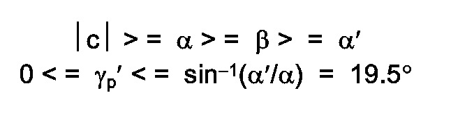
- For the Normal water-bottom, the following velocity relationships apply:

- Since the phase velocity of the arriving wave-front along the x-axis can be expressed as

then

- In like manner, the ranges of values for the angles γs and γp′ can be determined, resulting in

- Using the method described by White in the text Seismic Waves - Radiation, Transmission, and Attenuation (McGraw-Hill, 1965), to which reference may be made for further details, scalar and vector displacement potential functions can be derived as solutions to the elastic wave equation, subject to the boundary conditions imposed by the model of Figure 8. From these potential functions, the pressure and particle velocity waves which will strike
detectors 22 can be determined. - Using Whites' method, the following expressions are obtained for the pressure waves and particle velocity waves (in the-z direction) in the water:

where A₁′ = displacement potential amplitude
- Substituting the location of the detectors 22 (x=0, z=-zd) into the above expressions,

Recalling that
Substituting
into the above expression, the following are obtained
- The scalar potential function yielding these expressions for p′ and v′ indicates that they are frequency-domain representations of Dirac delta functions occurring at time

- They therefore correspond to the first arrivals of p(t) and v(t) of Figure 5.
- It will be appreciated that the ratio of v′ and p′ is

which corresponds to the ratio of the amplitudes of the first arrivals in Figure 5. The additional cosine factor accounts for the directivity of the velocity detector. - The expression relating p′ in the water to the incident pressure wave p is

where
- For normal incidence (c→∞), this expression reduces to the transmission coefficient T described above.
- For the Hard water-bottom, the following velocity relationships apply:

For
the ranges of angles for the various reflected and refracted waves can be calculated. The results are
and the expressions of [Eq. 3-1]-[Eq. 3-4] also apply to the Hard water-bottom case. - The velocity relationships for the Soft water-bottom case are

and for
all the preceding expressions also apply. - The ranges of the angles for this condition are:

- At this point, expressions for p(t) and v(t) corresponding to those of [Eq. 2-1] can be written as follows.

where KT is given in [Eq. 3-4] - In the model, an upward-propagating reflection wave has encountered the
detectors 22 at z=-zd and is preparing to strike the air/water interface. This is depicted in Figure 9 where, it will be noted, the origin of the coordinate system has been shifted to the surface of the water. - Solving the elastic wave equation subject to the boundary conditions imposed by this model, it is found that

and
- Substituting the position of our detectors (o₁ζd), and c=α′/sinγp′ into the above expressions,

- It will be noted that the first term of p′ and v′ each represent a wave traveling in the -ζ direction (upward) and the second term a wave traveling in the +ζ direction (downward). It will also be noted that they are again frequency domain representations of Dirac delta functions.
- The total time delay between the arrival of the above waves at our detectors is

- To relate this to the coordinate system of Figure 8, note that

Therefore
and substituting above,
- This represents the delay time between the arrival of the reflection of [Eq. 3-5] and the water surface ghost. Therefore, adding the time-domain representation of the downward-propagating components of [Eq. 3-6] to [Eq. 3-5] we obtain

- The downward-propagating wave is now ready to strike the water-bottom and to be partially reflected back toward our detectors. This model is shown in Figure 10.
- Once again, solving the elastic wave equation,

Substituting for the position of thedetectors 22
- Here, the first term of p′ and v′ each represents the upward-propagating wave and the second term the downward. The time delay between the arrival of the two waves at our detectors is

Updating p(t) and v(t) in [Eq. 3-7] yields
where
- The value of KR depends upon the water-bottom material and the angle of incidence as follows:
- For the condition

where

where
For
where
- For the condition
KR is given by [Eq. 3-10]
For
KR is given by [Eq. 3-11]
For
where
- For the condition

KR is given by [Eq. 3-10] - Referring back to the expressions for p(t) and v(t) in [Eq. 3-9] and comparing them to Figure 5, those skilled in the art will readily appreciate how to modify the signals of Figure 5 to account for non-vertical incidence. An illustration so modified is shown in Figure 11. In that figure, it can be seen that to cancel all downward- propagating waves, v(t) must be scaled by (ρ′α′/cosγp′) and added to p(t).

- Assuming, once again, that the
detectors 22 are placed at the water-bottom (zd=0), the signals of Figure 11 are modified as shown in Figure 12. Here, it is also seen that all water-column reverberations may be eliminated through proper choice of a scale factor. More particularly, this can be accomplished if v(t) is scaled as shown below and add it to p(t).
- As above, the scale factor required for v(t) involves the reflection coefficient of the water-bottom, and, therefore, its acoustic impedance. Methods for determining that scale factor are discussed in detail above.
Claims (10)
- A seismic reflection method of geophysical prospecting in water covered areas, comprising the steps of:A. generating a seismic wave for reflection from earth strata;B. detecting water pressure at a first position in the water resulting from said seismic wave and generating a signal representative thereof;C. detecting water velocity at a position substantially near said first position resulting from said seismic wave and generating a signal representative thereof; characterized byD. generating an enhanced seismic reflection signal by multiplying at least one of said water pressure-representative signal and the water velocity-representative signal by a scale factor dependent upon an acoustical impedance of a substance through which said seismic wave travels, and by summing said scaled water velocity-representative and water pressure-representative signals, said enhanced seismic reflection signal being substantially free of at least downwardly-propagating components of reverberation of said seismic wave within the water.
- A method according to claim 1, wherein a pressure detector and a velocity detector are positioned substantially near the bottom of the water for detecting said water pressure and said water velocity and for generating signals representative thereof.
- A method according to claim 2, wherein in step D the substance is solid earth material at the bottom of the water.
- A method according to claim 3, wherein said scaling step (i) includes the further step of multiplying said at least one selected signal by a value dependent upon

- A method according to claim 4, wherein said scaling step (i) includes the step of multiplying said at least one selected signal by a value dependent upon

- A method according to claim 4 or 5, wherein said scaling step (i) includes the step of generating said directivity correction factor, Dircorr, to be equal to cos(γp′) for γp′ less than a selected critical angle, and to otherwise be equal to 1, where γp′ is an angle of propagation from vertical of the seismic wave in the water.
- A method according to claim 6, wherein said scaling step (i) includes the step of determining said critical angle to be substantially equal to arcsin (α′/α), where α′ is the velocity of propagation of the seismic wave in the water and α is a velocity of propagation of the seismic wave in said solid earth material at the bottom of the water.
- A method according to claim 3, including the step of determining said scale factor deterministically.
- A method according to claim 8, where said scale factor determining step includes:(a) generating a pressure wave from a position above the position of said pressure and velocity detectors,(b) detecting, with said water pressure detector, water pressure during a selected arrival of said pressure wave and generating a signal representative thereof,(c) detecting, with said velocity detector, a signal representative of the water velocity during a selected arrival of said pressure wave and generating a signal representative thereof, and(d) determining said scale factor as dependent on a ratio of the absolute values of the magnitudes of the pressure wave velocity-representative signal and the pressure wave pressure-representative signal.
- A method according to claim 9, wherein said pressure wave-generating step includes the step of generating said pressure wave from a position directly over said pressure and velocity detectors, and wherein preferably said pressure wave pressure detecting step includes the step of detecting water pressure during a first arrival of said pressure wave, and preferably said pressure wave velocity detecting step includes the step of detecting water velocity during a first arrival of said pressure wave.
Applications Claiming Priority (2)
| Application Number | Priority Date | Filing Date | Title |
|---|---|---|---|
| US07/398,809 US4979150A (en) | 1989-08-25 | 1989-08-25 | System for attenuation of water-column reverberations |
| US398809 | 1989-08-25 |
Publications (3)
| Publication Number | Publication Date |
|---|---|
| EP0414344A2 EP0414344A2 (en) | 1991-02-27 |
| EP0414344A3 EP0414344A3 (en) | 1992-05-13 |
| EP0414344B1 true EP0414344B1 (en) | 1995-03-29 |
Family
ID=23576891
Family Applications (1)
| Application Number | Title | Priority Date | Filing Date |
|---|---|---|---|
| EP90306104A Expired - Lifetime EP0414344B1 (en) | 1989-08-25 | 1990-06-05 | Marine seismic reflection geophysical surveying |
Country Status (8)
| Country | Link |
|---|---|
| US (1) | US4979150A (en) |
| EP (1) | EP0414344B1 (en) |
| AU (1) | AU5716490A (en) |
| CA (1) | CA2019007C (en) |
| DE (1) | DE69018161T2 (en) |
| EG (1) | EG19158A (en) |
| MY (1) | MY106741A (en) |
| NO (1) | NO303033B1 (en) |
Families Citing this family (88)
| Publication number | Priority date | Publication date | Assignee | Title |
|---|---|---|---|---|
| US5163028A (en) * | 1991-09-27 | 1992-11-10 | Halliburton Geophysical Services, Inc. | Method for correcting impulse response differences of hydrophones and geophones as well as geophone coupling to the water-bottom in dual-sensor, bottom-cable seismic operations |
| US5278774A (en) * | 1991-10-01 | 1994-01-11 | Rockwell International Corporation | Alarm for transient underwater events |
| US5408440A (en) * | 1993-03-19 | 1995-04-18 | Western Atlas International, Inc. | Hydrophone circuit with electrical characteristics of a geophone |
| US5365492A (en) * | 1993-08-04 | 1994-11-15 | Western Atlas International, Inc. | Method for reverberation suppression |
| US5396472A (en) * | 1993-09-24 | 1995-03-07 | Western Atlas International | Method for deriving water bottom reflectivity in dual sensor seismic surveys |
| US5774416A (en) * | 1995-04-07 | 1998-06-30 | Pgs, Tensor, Inc. | Method and device for attenuating water column reverberations using co-located hydrophones and geophones in ocean bottom seismic processing |
| US5621699A (en) * | 1995-07-07 | 1997-04-15 | Pgs Ocean Bottom Seismic, Inc. | Apparatus and method of calibrating vertical particle velocity detector and pressure detector in a sea-floor cable with in-situ passive monitoring |
| US5724306A (en) | 1995-12-29 | 1998-03-03 | Western Atlas International, Inc. | Method for correcting dual sensor data for imperfect geophone coupling using production seismic data |
| FR2743896B1 (en) * | 1996-01-23 | 1998-04-10 | Geophysique Cie Gle | METHOD FOR PROCESSING FOR CALIBRATION OF A PAIR OF HYDROPHONE/GEOPHONE SENSORS AND METHOD FOR SEISMIC PROSPECTING IMPLEMENTING THIS PROCESSING |
| FR2743897B1 (en) * | 1996-01-23 | 1998-04-10 | Geophysique Cie Gle | PROCESS FOR MARINE SEISMIC PROSPECTION USING A COUPLE OF HYDROPHONE AND GEOPHONE SENSORS |
| US5754492A (en) * | 1996-02-12 | 1998-05-19 | Pgs Tensor, Inc. | Method of reverberation removal from seismic data and removal of dual sensor coupling errors |
| US5696734A (en) * | 1996-04-30 | 1997-12-09 | Atlantic Richfield Company | Method and system for eliminating ghost reflections from ocean bottom cable seismic survey signals |
| US5621700A (en) * | 1996-05-20 | 1997-04-15 | Schlumberger Technology Corporation, Geco-Prakla Div. | Method for attenuation of reverberations using a pressure-velocity bottom cable |
| US5793702A (en) * | 1996-05-21 | 1998-08-11 | Western Atlas International, Inc. | Method for measuring the water bottom reflectivity |
| US5774417A (en) * | 1996-10-25 | 1998-06-30 | Atlantic Richfield Company | Amplitude and phase compensation in dual-sensor ocean bottom cable seismic data processing |
| US5724307A (en) * | 1997-04-14 | 1998-03-03 | Western Atlas International, Inc. | Method for improving the coupling response of a water-bottom seismic sensor |
| US6201764B1 (en) * | 1997-10-31 | 2001-03-13 | Input/Output, Inc. | Apparatus and method for correcting for capacitance variations in hydrophones |
| GB9800741D0 (en) * | 1998-01-15 | 1998-03-11 | Geco As | Multiple attenuation of multi-component sea-bottom data |
| US5991238A (en) * | 1998-06-09 | 1999-11-23 | Western Atlas International, Inc. | Weighted backus filter method of combining dual sensor traces |
| GB9906995D0 (en) | 1998-09-16 | 1999-05-19 | Geco Prakla Uk Ltd | Seismic detection apparatus and related method |
| US6246637B1 (en) | 1998-09-28 | 2001-06-12 | Pgs Tensor, Inc. | Method and system for combining three component seismic data |
| GB9906456D0 (en) * | 1999-03-22 | 1999-05-12 | Geco Prakla Uk Ltd | Method and system for reducing effects of sea surface ghost contamination in seismic data |
| US6539308B2 (en) | 1999-06-25 | 2003-03-25 | Input/Output Inc. | Dual sensor signal processing method for on-bottom cable seismic |
| US6314371B1 (en) * | 1999-06-25 | 2001-11-06 | Input/Output, Inc. | Dual sensor signal processing method for on-bottom cable seismic wave detection |
| US6263285B1 (en) | 1999-09-15 | 2001-07-17 | Pgs Tensor, Inc. | Amplitude spectra estimation |
| CN1188711C (en) * | 2000-01-21 | 2005-02-09 | 施鲁博格控股有限公司 | System and method for seismic wave field separation |
| AU774883B2 (en) * | 2000-01-21 | 2004-07-08 | Schlumberger Holdings Limited | System and method for estimating seismic material properties |
| GB0015810D0 (en) * | 2000-06-29 | 2000-08-23 | Geco As | A method of processing seismic data |
| US20020118602A1 (en) | 2001-02-27 | 2002-08-29 | Sen Mrinal K. | Angle dependent surface multiple attenuation for two-component marine bottom sensor data |
| WO2002097472A2 (en) | 2001-05-25 | 2002-12-05 | Exxonmobil Upstream Research Company | Multiple suppression for ocean bottom seismic data |
| US6738715B2 (en) | 2001-09-14 | 2004-05-18 | Exxonmobil Upstream Research Company | Method for attenuating noise in seismic data |
| US7239577B2 (en) * | 2002-08-30 | 2007-07-03 | Pgs Americas, Inc. | Apparatus and methods for multicomponent marine geophysical data gathering |
| US6937938B2 (en) | 2002-09-04 | 2005-08-30 | Stanley A. Sansone | Method and apparatus for interferometry, spectral analysis, and three-dimensional holographic imaging of hydrocarbon accumulations and buried objects |
| US6763305B2 (en) | 2002-09-13 | 2004-07-13 | Gx Technology Corporation | Subsurface illumination, a hybrid wave equation-ray-tracing method |
| WO2004086094A1 (en) * | 2003-03-26 | 2004-10-07 | Westergeco Seismic Holdings Limited | Processing seismic data representative of the acceleration wavefield |
| US7561493B2 (en) * | 2003-05-30 | 2009-07-14 | Fairfield Industries, Inc. | Method and apparatus for land based seismic data acquisition |
| US7310287B2 (en) | 2003-05-30 | 2007-12-18 | Fairfield Industries Incorporated | Method and apparatus for seismic data acquisition |
| US7123543B2 (en) * | 2003-07-16 | 2006-10-17 | Pgs Americas, Inc. | Method for seismic exploration utilizing motion sensor and pressure sensor data |
| GB2404736B (en) * | 2003-08-01 | 2006-01-04 | Westerngeco Seismic Holdings | Determination of geophone coupling |
| GB2405473B (en) * | 2003-08-23 | 2005-10-05 | Westerngeco Ltd | Multiple attenuation method |
| US6943729B2 (en) * | 2003-10-01 | 2005-09-13 | S5 Wireless, Inc. | Method and system for time difference of arrival (TDOA) location services |
| GB2410551B (en) * | 2004-01-30 | 2006-06-14 | Westerngeco Ltd | Marine seismic acquisition system |
| US7359283B2 (en) * | 2004-03-03 | 2008-04-15 | Pgs Americas, Inc. | System for combining signals of pressure sensors and particle motion sensors in marine seismic streamers |
| US7139217B2 (en) * | 2004-05-27 | 2006-11-21 | Pgs Americas, Inc. | Water bottom cable seismic survey cable and system |
| KR100741875B1 (en) * | 2004-09-06 | 2007-07-23 | 동부일렉트로닉스 주식회사 | CMOS Image sensor and method for fabricating the same |
| US7336561B2 (en) * | 2004-09-07 | 2008-02-26 | Pgs Americas, Inc. | System for attenuation of water bottom multiples in seismic data recorded by pressure sensors and particle motion sensors |
| US7450468B2 (en) * | 2004-10-19 | 2008-11-11 | Landmark Graphics Corporation | Methods, systems, and computer readable media for interactively determining parameters for ocean-bottom hydrophone/geophone receiver combination deghosting |
| US20060133202A1 (en) * | 2004-12-22 | 2006-06-22 | Tenghamn Stig R L | Motion sensors in a marine seismic streamer |
| US8534959B2 (en) | 2005-01-17 | 2013-09-17 | Fairfield Industries Incorporated | Method and apparatus for deployment of ocean bottom seismometers |
| US7477992B2 (en) * | 2005-02-18 | 2009-01-13 | Exxonmobil Upstream Research Company | Method for combining seismic data sets |
| US7319636B2 (en) * | 2005-03-14 | 2008-01-15 | Westerngeco, L.L.C. | Calibration of pressure gradient recordings |
| US20060209633A1 (en) * | 2005-03-17 | 2006-09-21 | George Nicholas C | Ocean bottom seismic sensor cable system including torque-relieving swivel |
| US8127706B2 (en) * | 2005-05-02 | 2012-03-06 | Fairfield Industries Incorporated | Deck configuration for ocean bottom seismometer launch platforms |
| US7768869B2 (en) * | 2005-05-05 | 2010-08-03 | Pgs Americas, Inc. | Method for deghosting and water layer multiple reflection attenuation in marine seismic data |
| US7590028B2 (en) * | 2005-05-12 | 2009-09-15 | Westerngeco L.L.C. | Seabed seismic cables and methods of stabilizing same when deployed on a seabed |
| US7623414B2 (en) * | 2006-02-22 | 2009-11-24 | Westerngeco L.L.C. | Particle motion vector measurement in a towed, marine seismic cable |
| US7167413B1 (en) | 2006-05-01 | 2007-01-23 | Input/Output | Towed streamer deghosting |
| US7466625B2 (en) * | 2006-06-23 | 2008-12-16 | Westerngeco L.L.C. | Noise estimation in a vector sensing streamer |
| US8559267B2 (en) * | 2006-10-26 | 2013-10-15 | Schlumberger Technology Corporation | Methods and apparatus of borehole seismic surveys |
| US8243547B2 (en) * | 2006-12-15 | 2012-08-14 | Exxonmobil Upstream Research Co. | Identification and suppression of multiples in ocean bottom seismic data |
| US20080144435A1 (en) * | 2006-12-15 | 2008-06-19 | Morley Lawrence C | Deep low frequency towed-array marine survey |
| US8593907B2 (en) * | 2007-03-08 | 2013-11-26 | Westerngeco L.L.C. | Technique and system to cancel noise from measurements obtained from a multi-component streamer |
| US8553490B2 (en) * | 2007-11-09 | 2013-10-08 | Pgs Geophysical As | Array grouping of seismic sensors in a marine streamer for optimum noise attenuation |
| US8781749B2 (en) * | 2007-12-28 | 2014-07-15 | Westerngeco L.L.C. | Attenuating noise in seismic data |
| US8611191B2 (en) * | 2008-05-22 | 2013-12-17 | Fairfield Industries, Inc. | Land based unit for seismic data acquisition |
| US7675812B2 (en) | 2008-06-30 | 2010-03-09 | Pgs Geophysical As | Method for attenuation of multiple reflections in seismic data |
| US9207349B2 (en) | 2008-08-27 | 2015-12-08 | Pgs Geophysical As | Methods and apparatus for determining seismic streamer array geometry and seismic sensor response |
| US8089825B2 (en) * | 2008-08-29 | 2012-01-03 | Pgs Geophysical As | Method of summing dual-sensor towed streamer signals using cross-ghosting analysis |
| DE102009034444A1 (en) * | 2009-07-23 | 2011-01-27 | Siemens Aktiengesellschaft | Method for monitoring an environment with multiple acoustic sensors |
| US20110044127A1 (en) * | 2009-08-19 | 2011-02-24 | Clement Kostov | Removing free-surface effects from seismic data acquired in a towed survey |
| US9110187B2 (en) * | 2009-10-05 | 2015-08-18 | Westerngeco L.L.C. | Sensor assembly having a seismic sensor and a divergence sensor |
| US8712694B2 (en) * | 2009-10-05 | 2014-04-29 | Westerngeco L.L.C. | Combining seismic data from sensors to attenuate noise |
| US8838392B2 (en) * | 2009-10-05 | 2014-09-16 | Westerngeco L.L.C. | Noise attenuation in passive seismic data |
| US20110085417A1 (en) * | 2009-10-12 | 2011-04-14 | Daniel Ronnow | String of Sensor Assemblies Having a Seismic Sensor and Pressure Sensor |
| US8520469B2 (en) * | 2009-10-12 | 2013-08-27 | Westerngeco L.L.C. | Sensor assembly having a seismic sensor, pressure sensor, and processor to apply first and second digital filters |
| FR2955397B1 (en) * | 2010-01-15 | 2012-03-02 | Cggveritas Services Sa | METHOD AND DEVICE FOR ACQUIRING MARINE SEISMIC DATA |
| FR2955396B1 (en) | 2010-01-15 | 2013-03-01 | Cggveritas Services Sa | DEVICE FOR PROCESSING SEISMIC MARINE DATA |
| CA2787296C (en) | 2010-01-22 | 2018-11-20 | Ion Geophysical Corporation | Seismic system with ghost and motion rejection |
| US8902699B2 (en) * | 2010-03-30 | 2014-12-02 | Pgs Geophysical As | Method for separating up and down propagating pressure and vertical velocity fields from pressure and three-axial motion sensors in towed streamers |
| FR2961316A1 (en) | 2010-06-10 | 2011-12-16 | Cggveritas Services Sa | PROCESS FOR PROCESSING SEISMIC MARINE DATA |
| US20110310698A1 (en) | 2010-06-21 | 2011-12-22 | Sercel, Inc. | Dual Axis Geophones For Pressure/Velocity Sensing Streamers Forming a Triple Component Streamer |
| RU2562711C2 (en) | 2010-09-02 | 2015-09-10 | Ион Геофизикал Корпорейшн | Multicomponent acoustic wave sensor and methods |
| AU2011232767B2 (en) * | 2010-10-14 | 2014-05-08 | Cggveritas Services Sa | Method and device to acquire seismic data |
| US9091783B2 (en) | 2010-11-04 | 2015-07-28 | Westerngeco L.L.C. | Computing a calibration term based on combining divergence data and seismic data |
| US9594174B2 (en) | 2013-02-01 | 2017-03-14 | Westerngeco L.L.C. | Computing rotation data using a gradient of translational data |
| US9841519B2 (en) | 2013-03-14 | 2017-12-12 | Ion Geophysical Corporation | Seismic sensor devices, systems, and methods including noise filtering |
| US10408954B2 (en) | 2014-01-17 | 2019-09-10 | Westerngeco L.L.C. | Seismic sensor coupling |
| US11493652B2 (en) * | 2018-09-05 | 2022-11-08 | Pgs Geophysical As | Two-axis sensing element |
Family Cites Families (89)
| Publication number | Priority date | Publication date | Assignee | Title |
|---|---|---|---|---|
| USRE23552E (en) * | 1952-09-30 | Apparatus for marine seismic prospecting | ||
| US1584613A (en) * | 1920-02-25 | 1926-05-11 | Kalmus Comstock & Wescott Inc | Wave detector |
| US2627930A (en) * | 1948-07-09 | 1953-02-10 | Atlantic Refining Co | Apparatus for underwater seismic operations |
| US2753948A (en) * | 1952-09-29 | 1956-07-10 | Int Research & Dev Co Ltd | Filtering cell prod for vibratory pick-up devices |
| US2923367A (en) * | 1952-10-06 | 1960-02-02 | Sun Oil Co | Method and apparatus for seismic surveying |
| US3286227A (en) * | 1953-02-20 | 1966-11-15 | Gerard T Aldrich | Line hydrophone |
| US2882988A (en) * | 1953-03-16 | 1959-04-21 | Socony Mobil Oil Co Inc | Elimination of near surface reflection effects |
| US2740945A (en) * | 1953-07-06 | 1956-04-03 | United Geophysical Corp | Seismic prospecting system |
| US2757356A (en) * | 1954-01-08 | 1956-07-31 | Texas Instruments Inc | Method and apparatus for canceling reverberations in water layers |
| US2791757A (en) * | 1954-03-24 | 1957-05-07 | California Research Corp | Pressure cable construction |
| US2807793A (en) * | 1954-10-01 | 1957-09-24 | Exxon Research Engineering Co | Continuous reelable geophone |
| US2856594A (en) * | 1955-03-04 | 1958-10-14 | Vector Mfg Company | Seismic detector |
| US2906992A (en) * | 1957-05-23 | 1959-09-29 | Kenneth H Wilcoxon | Towed hydrophone |
| US3964424A (en) * | 1958-04-02 | 1976-06-22 | The United States Of America As Represented By The Secretary Of The Navy | Influence detecting gear with improved towing characteristics |
| US3054085A (en) * | 1958-08-25 | 1962-09-11 | Jersey Prod Res Co | Self-orienting geophone |
| US3274542A (en) * | 1963-03-25 | 1966-09-20 | Socony Mobil Oil Co Inc | Methods of band-equalizing seismograms |
| US3290645A (en) * | 1964-02-13 | 1966-12-06 | Whitehall Electronics Corp | Method and underwater streamer apparatus for improving the fidelity of recorded seismic signals |
| US3343626A (en) * | 1965-01-18 | 1967-09-26 | Pan American Petroleum Corp | Cancelling seismic multiple reflections by transmitting only the down-travelling seismic signals detected from the original transmitted signal |
| US3304364A (en) * | 1965-01-25 | 1967-02-14 | Stauffer Chemical Co | Conducting tow line structure |
| US3299397A (en) * | 1965-03-08 | 1967-01-17 | Sonic Engineering Company | Underwater detector streamer apparatus for improving the fidelity of recorded seismic signals |
| US3281768A (en) * | 1965-03-11 | 1966-10-25 | Sonic Engineering Company | Method and cardioid system comprising pressure sensor means with output compensated displacement or acceleration sensor |
| FR91705E (en) * | 1965-05-22 | 1968-08-02 | Inst Francais Du Petrole | Pressure sensors insensitive to noise |
| US3319734A (en) * | 1965-06-17 | 1967-05-16 | Whitehall Electronics Corp | Elastic detection streamer dead section for a water borne seismic surveying system |
| US3354984A (en) * | 1965-08-19 | 1967-11-28 | Whitehall Electronics Corp | Depth controlled marine seismic detection cable |
| US3350683A (en) * | 1966-03-08 | 1967-10-31 | Mobil Oil Corp | Optimum detector type and depth in marine seismic exploration |
| US3354860A (en) * | 1966-06-27 | 1967-11-28 | John R Dale | Mechanical isolation of hydrophones by hydroplanes |
| US3369216A (en) * | 1966-07-28 | 1968-02-13 | Mobil Oil Corp | System for reducing the transmission of noise in marine seismic surveying |
| US3409871A (en) * | 1966-10-12 | 1968-11-05 | Exxon Production Research Co | Elimination of multiple events on seismograms obtained at water-covered areas of the earth |
| US3491848A (en) * | 1968-01-10 | 1970-01-27 | Texas Instruments Inc | Wave generator arrays for marine seismic exploration |
| US3441902A (en) * | 1968-04-01 | 1969-04-29 | Western Geophysical Co | Extendable intersection hydrophone arrays |
| US3518677A (en) * | 1968-09-16 | 1970-06-30 | Mark Products | Electric marine cable |
| US3860899A (en) * | 1968-10-08 | 1975-01-14 | Us Navy | Strum noise reducing device |
| US3739328A (en) * | 1970-07-13 | 1973-06-12 | Schlumberger Technology Corp | Acoustic impedance logging using reflection coefficients |
| US3696329A (en) * | 1970-11-12 | 1972-10-03 | Mark Products | Marine streamer cable |
| GB1316479A (en) * | 1970-11-23 | 1973-05-09 | Mobil Oil Corp | Seismic data records by frequency domain operation |
| US3710006A (en) * | 1971-07-01 | 1973-01-09 | Schlumberger Technology Corp | Marine streamer cable |
| US3866161A (en) * | 1973-01-24 | 1975-02-11 | Petty Ray Geophysical Inc | Method and apparatus for obtaining a more accurate measure of input seismic energy |
| US3863201A (en) * | 1973-05-29 | 1975-01-28 | Amoco Prod Co | Seismometer arrays using operational amplifiers |
| US3943484A (en) * | 1973-11-26 | 1976-03-09 | Avance Oil & Gas Company, Inc. | Method of attenuating unwanted seismic reflections in underwater seismic exploration |
| US3893065A (en) * | 1973-12-05 | 1975-07-01 | Sperry Rand Corp | Hydrophone array |
| US3930254A (en) * | 1974-04-09 | 1975-12-30 | Whitehall Corp | Seismic streamer construction for minimizing hydrophone response to vibration produced pressure fields |
| US3979713A (en) * | 1974-08-19 | 1976-09-07 | Texaco Inc. | Method of marine reflection-type seismic exploration |
| US3932835A (en) * | 1974-09-25 | 1976-01-13 | The United States Of America As Represented By The Secretary Of The Navy | Towable VLF sonar projector |
| US4146871A (en) * | 1975-02-28 | 1979-03-27 | Mobil Oil Corporation | Determination of reflectivity and water depth for firing marine sources as an inverse distortion operator |
| US3990039A (en) * | 1975-04-07 | 1976-11-02 | Miller Larry D | Tuned ground motion detector utilizing principles of mechanical resonance |
| US4348749A (en) * | 1975-06-30 | 1982-09-07 | Mobil Oil Corporation | Phase correcting seismic traces |
| US4038630A (en) * | 1975-10-28 | 1977-07-26 | Bolt Associates, Inc. | Airgun marine seismic survey streamer method and apparatus |
| US4160229A (en) * | 1976-07-08 | 1979-07-03 | Honeywell Inc. | Concentric tube hydrophone streamer |
| US4078223A (en) * | 1976-09-10 | 1978-03-07 | Western Geophysical Co. Of America | Geophone and seismic cable assembly |
| US4210897A (en) * | 1976-12-06 | 1980-07-01 | Huntec (70) Limited | Heave compensation system |
| US4090168A (en) * | 1977-05-17 | 1978-05-16 | The United States Of America As Represented By The Secretary Of The Navy | Solid filled vibration isolation module for a towed sonar array |
| US4134097A (en) * | 1977-06-13 | 1979-01-09 | Shell Oil Company | Combination geophone-hydrophone |
| US4117447A (en) * | 1977-08-29 | 1978-09-26 | The United States Of America As Represented By The Secretary Of The Navy | Bouyant electrode with anti-birdnesting device |
| CA1128189A (en) * | 1977-09-21 | 1982-07-20 | Standard Oil Company | Field fan filter |
| CA1137205A (en) * | 1978-08-17 | 1982-12-07 | Roger W. Hutchins | Body motion compensation filter |
| US4276620A (en) * | 1978-10-27 | 1981-06-30 | Geosource Inc. | Method and apparatus for obtaining a composite field response _to a variable source array using weighting coefficients |
| US4296481A (en) * | 1979-12-17 | 1981-10-20 | Exploration Company | Streamer bulkhead |
| US4317185A (en) * | 1980-06-06 | 1982-02-23 | Western Geophysical Co. Of America | Streamer cable towing link |
| US4353121A (en) * | 1980-07-24 | 1982-10-05 | Fairfield Industries, Inc. | High resolution, marine seismic stratigraphic system |
| US4380059A (en) * | 1980-08-20 | 1983-04-12 | Mobil Oil Corporation | F-K Filtering of multiple reflections from a seismic section |
| US4486865A (en) * | 1980-09-02 | 1984-12-04 | Mobil Oil Corporation | Pressure and velocity detectors for seismic exploration |
| US4345473A (en) * | 1980-11-26 | 1982-08-24 | Shell Oil Company | Vertical component accelerometer |
| US4402069A (en) * | 1981-06-03 | 1983-08-30 | The United States Of America As Represented By The Secretary Of The Navy | Acoustic envelope having minimal vibration and flow induced noises |
| US4477887A (en) * | 1981-09-08 | 1984-10-16 | Shell Oil Company | Low noise mounting for accelerometer used in marine cable |
| US4415997A (en) * | 1981-11-12 | 1983-11-15 | Mobil Oil Corporation | Method for determining source and receiver statics in marine seismic exploration |
| US4437175A (en) * | 1981-11-20 | 1984-03-13 | Shell Oil Company | Marine seismic system |
| US4449208A (en) * | 1981-11-23 | 1984-05-15 | Mobil Oil Corporation | Lithologic studies utilizing acoustic wave attenuation |
| US4510588A (en) * | 1981-12-22 | 1985-04-09 | Shell Oil Company | Hydrophone cable decoupler |
| USH387H (en) * | 1981-12-22 | 1987-12-01 | Shell Oil Company | Wavelength filter for marine seismic cables |
| US4837751A (en) * | 1981-12-22 | 1989-06-06 | Shell Oil Company | Shielded hydrophone assembly |
| US4520467A (en) * | 1982-03-18 | 1985-05-28 | Shell Oil Company | Marine seismic system |
| US4439497A (en) * | 1982-05-27 | 1984-03-27 | Shell Oil Company | Ultrasonic sound absorber |
| US4679179A (en) * | 1982-06-15 | 1987-07-07 | Raychem Corporation | Sonar detection apparatus |
| DE3373713D1 (en) * | 1982-06-28 | 1987-10-22 | Britoil Plc | Scaling of sound source signatures in underwater seismic exploration |
| US4633449A (en) * | 1982-10-15 | 1986-12-30 | Ingram John D | Method and apparatus for indirect determination of shear velocity from guided modes |
| US4581724A (en) * | 1983-12-12 | 1986-04-08 | Mobil Oil Corporation | Method for determining source and receiver statics in marine seismic exploration |
| US4644508A (en) * | 1983-12-28 | 1987-02-17 | Mobil Oil Corporation | Method and apparatus for selectively reinforcing detected seismic waves |
| US4752916A (en) * | 1984-08-28 | 1988-06-21 | Dan Loewenthal | Method and system for removing the effect of the source wavelet from seismic data |
| US4733379A (en) * | 1984-10-15 | 1988-03-22 | Edo Corporation/Western Division | Line array transducer assembly |
| US4660183A (en) * | 1985-09-10 | 1987-04-21 | Hughes Aircraft Company | Vibration isolation module for sonar towed arrays |
| US4685090A (en) * | 1985-11-27 | 1987-08-04 | Raychem Corporation | Tubular article |
| US4733378A (en) * | 1986-06-06 | 1988-03-22 | Western Atlas International, Inc. | Active low-profile hydrophone |
| US4734891A (en) * | 1986-06-20 | 1988-03-29 | Hughes Aircraft Company | Aft drogue module for towed sonar array |
| US4809243A (en) * | 1986-10-03 | 1989-02-28 | Western Atlas International, Inc. | Streamer cable |
| US4765436A (en) * | 1986-12-10 | 1988-08-23 | Duke University | Dry friction damper with damping force perpendicular to principal direction of a vibration |
| US4736345A (en) * | 1987-03-27 | 1988-04-05 | Mobil Oil Corporation | Compliant spacer for a marine seismic streamer |
| US4813028A (en) * | 1987-07-07 | 1989-03-14 | Schlumberger Technology Corporation | Acoustic well logging method and apparatus |
| US4794573A (en) * | 1988-02-11 | 1988-12-27 | Conoco Inc. | Process for separating upgoing and downgoing events on vertical seismic profiles |
| US4821241A (en) * | 1988-05-23 | 1989-04-11 | Teledyne Exploration Co. | Noise-cancelling streamer cable |
-
1989
- 1989-07-11 EG EG41789A patent/EG19158A/en active
- 1989-08-25 US US07/398,809 patent/US4979150A/en not_active Expired - Lifetime
-
1990
- 1990-06-05 DE DE69018161T patent/DE69018161T2/en not_active Expired - Fee Related
- 1990-06-05 EP EP90306104A patent/EP0414344B1/en not_active Expired - Lifetime
- 1990-06-14 CA CA002019007A patent/CA2019007C/en not_active Expired - Fee Related
- 1990-06-14 AU AU57164/90A patent/AU5716490A/en not_active Abandoned
- 1990-06-15 MY MYPI90001007A patent/MY106741A/en unknown
- 1990-06-28 NO NO902886A patent/NO303033B1/en not_active IP Right Cessation
Also Published As
| Publication number | Publication date |
|---|---|
| MY106741A (en) | 1995-07-31 |
| NO303033B1 (en) | 1998-05-18 |
| EP0414344A2 (en) | 1991-02-27 |
| DE69018161T2 (en) | 1995-09-07 |
| CA2019007A1 (en) | 1991-02-25 |
| CA2019007C (en) | 1999-01-26 |
| EP0414344A3 (en) | 1992-05-13 |
| NO902886L (en) | 1991-02-26 |
| NO902886D0 (en) | 1990-06-28 |
| EG19158A (en) | 1996-02-29 |
| US4979150A (en) | 1990-12-18 |
| AU5716490A (en) | 1991-02-28 |
| DE69018161D1 (en) | 1995-05-04 |
Similar Documents
| Publication | Publication Date | Title |
|---|---|---|
| EP0414344B1 (en) | Marine seismic reflection geophysical surveying | |
| US7359283B2 (en) | System for combining signals of pressure sensors and particle motion sensors in marine seismic streamers | |
| US7505361B2 (en) | Method for prediction of surface related multiples from marine towed dual sensor seismic streamer data | |
| US8396668B2 (en) | Marine seismic surveying employing interpolated multicomponent streamer pressure data | |
| EP0534648B1 (en) | Method of marine seismic exploration | |
| EP2389601B1 (en) | Method for wavefield separation for dual-sensor data using kirchhoff-type datuming and migration | |
| Barr | Dual-sensor OBC technology | |
| EP2189818B1 (en) | Method of wavefield extrapolation for single-station, dual-sensor towed streamer signals | |
| EP2249182B1 (en) | Method for calculation of seismic attributes from seismic signals | |
| US8089825B2 (en) | Method of summing dual-sensor towed streamer signals using cross-ghosting analysis | |
| US8937848B2 (en) | Methods and systems to eliminate undesirable variations in time-lapse seismic surveys | |
| US20080144435A1 (en) | Deep low frequency towed-array marine survey | |
| US5579282A (en) | Method for determining the shear-wave velocity beneath a body of water | |
| GB2448831A (en) | Combining the signals from pressure and particle motion sensors in marine seismic streamers | |
| Robinson | REMOTE DETECTION USING DUAL SENSORS |
Legal Events
| Date | Code | Title | Description |
|---|---|---|---|
| PUAI | Public reference made under article 153(3) epc to a published international application that has entered the european phase |
Free format text: ORIGINAL CODE: 0009012 |
|
| AK | Designated contracting states |
Kind code of ref document: A2 Designated state(s): DE DK FR GB IT NL SE |
|
| PUAL | Search report despatched |
Free format text: ORIGINAL CODE: 0009013 |
|
| AK | Designated contracting states |
Kind code of ref document: A3 Designated state(s): DE DK FR GB IT NL SE |
|
| 17P | Request for examination filed |
Effective date: 19920930 |
|
| 17Q | First examination report despatched |
Effective date: 19930701 |
|
| RAP1 | Party data changed (applicant data changed or rights of an application transferred) |
Owner name: WESTERN ATLAS INTERNATIONAL, INC. |
|
| GRAA | (expected) grant |
Free format text: ORIGINAL CODE: 0009210 |
|
| AK | Designated contracting states |
Kind code of ref document: B1 Designated state(s): DE DK FR GB IT NL SE |
|
| PG25 | Lapsed in a contracting state [announced via postgrant information from national office to epo] |
Ref country code: DK Effective date: 19950329 |
|
| ITF | It: translation for a ep patent filed | ||
| REF | Corresponds to: |
Ref document number: 69018161 Country of ref document: DE Date of ref document: 19950504 |
|
| PG25 | Lapsed in a contracting state [announced via postgrant information from national office to epo] |
Ref country code: SE Effective date: 19950629 |
|
| ET | Fr: translation filed | ||
| PLBE | No opposition filed within time limit |
Free format text: ORIGINAL CODE: 0009261 |
|
| STAA | Information on the status of an ep patent application or granted ep patent |
Free format text: STATUS: NO OPPOSITION FILED WITHIN TIME LIMIT |
|
| 26N | No opposition filed | ||
| REG | Reference to a national code |
Ref country code: GB Ref legal event code: IF02 |
|
| PGFP | Annual fee paid to national office [announced via postgrant information from national office to epo] |
Ref country code: DE Payment date: 20030630 Year of fee payment: 14 |
|
| PG25 | Lapsed in a contracting state [announced via postgrant information from national office to epo] |
Ref country code: DE Free format text: LAPSE BECAUSE OF NON-PAYMENT OF DUE FEES Effective date: 20050101 |
|
| PGFP | Annual fee paid to national office [announced via postgrant information from national office to epo] |
Ref country code: NL Payment date: 20090603 Year of fee payment: 20 |
|
| PGFP | Annual fee paid to national office [announced via postgrant information from national office to epo] |
Ref country code: IT Payment date: 20090622 Year of fee payment: 20 |
|
| PGFP | Annual fee paid to national office [announced via postgrant information from national office to epo] |
Ref country code: GB Payment date: 20090603 Year of fee payment: 20 |
|
| REG | Reference to a national code |
Ref country code: NL Ref legal event code: V4 Effective date: 20100605 |
|
| REG | Reference to a national code |
Ref country code: GB Ref legal event code: PE20 Expiry date: 20100604 |
|
| PG25 | Lapsed in a contracting state [announced via postgrant information from national office to epo] |
Ref country code: NL Free format text: LAPSE BECAUSE OF EXPIRATION OF PROTECTION Effective date: 20100605 |
|
| PG25 | Lapsed in a contracting state [announced via postgrant information from national office to epo] |
Ref country code: GB Free format text: LAPSE BECAUSE OF EXPIRATION OF PROTECTION Effective date: 20100604 |
|
| PGFP | Annual fee paid to national office [announced via postgrant information from national office to epo] |
Ref country code: FR Payment date: 20090611 Year of fee payment: 20 |