EP0414270A2 - Fuel cell utilizing solidous electrolyte - Google Patents
Fuel cell utilizing solidous electrolyte Download PDFInfo
- Publication number
- EP0414270A2 EP0414270A2 EP90116284A EP90116284A EP0414270A2 EP 0414270 A2 EP0414270 A2 EP 0414270A2 EP 90116284 A EP90116284 A EP 90116284A EP 90116284 A EP90116284 A EP 90116284A EP 0414270 A2 EP0414270 A2 EP 0414270A2
- Authority
- EP
- European Patent Office
- Prior art keywords
- fuel cell
- film
- set forth
- solidous
- forming
- Prior art date
- Legal status (The legal status is an assumption and is not a legal conclusion. Google has not performed a legal analysis and makes no representation as to the accuracy of the status listed.)
- Granted
Links
Images


Classifications
-
- H—ELECTRICITY
- H01—ELECTRIC ELEMENTS
- H01M—PROCESSES OR MEANS, e.g. BATTERIES, FOR THE DIRECT CONVERSION OF CHEMICAL ENERGY INTO ELECTRICAL ENERGY
- H01M8/00—Fuel cells; Manufacture thereof
- H01M8/02—Details
-
- H—ELECTRICITY
- H01—ELECTRIC ELEMENTS
- H01M—PROCESSES OR MEANS, e.g. BATTERIES, FOR THE DIRECT CONVERSION OF CHEMICAL ENERGY INTO ELECTRICAL ENERGY
- H01M4/00—Electrodes
- H01M4/86—Inert electrodes with catalytic activity, e.g. for fuel cells
- H01M4/88—Processes of manufacture
- H01M4/8878—Treatment steps after deposition of the catalytic active composition or after shaping of the electrode being free-standing body
- H01M4/8896—Pressing, rolling, calendering
-
- C—CHEMISTRY; METALLURGY
- C23—COATING METALLIC MATERIAL; COATING MATERIAL WITH METALLIC MATERIAL; CHEMICAL SURFACE TREATMENT; DIFFUSION TREATMENT OF METALLIC MATERIAL; COATING BY VACUUM EVAPORATION, BY SPUTTERING, BY ION IMPLANTATION OR BY CHEMICAL VAPOUR DEPOSITION, IN GENERAL; INHIBITING CORROSION OF METALLIC MATERIAL OR INCRUSTATION IN GENERAL
- C23C—COATING METALLIC MATERIAL; COATING MATERIAL WITH METALLIC MATERIAL; SURFACE TREATMENT OF METALLIC MATERIAL BY DIFFUSION INTO THE SURFACE, BY CHEMICAL CONVERSION OR SUBSTITUTION; COATING BY VACUUM EVAPORATION, BY SPUTTERING, BY ION IMPLANTATION OR BY CHEMICAL VAPOUR DEPOSITION, IN GENERAL
- C23C14/00—Coating by vacuum evaporation, by sputtering or by ion implantation of the coating forming material
- C23C14/06—Coating by vacuum evaporation, by sputtering or by ion implantation of the coating forming material characterised by the coating material
-
- C—CHEMISTRY; METALLURGY
- C23—COATING METALLIC MATERIAL; COATING MATERIAL WITH METALLIC MATERIAL; CHEMICAL SURFACE TREATMENT; DIFFUSION TREATMENT OF METALLIC MATERIAL; COATING BY VACUUM EVAPORATION, BY SPUTTERING, BY ION IMPLANTATION OR BY CHEMICAL VAPOUR DEPOSITION, IN GENERAL; INHIBITING CORROSION OF METALLIC MATERIAL OR INCRUSTATION IN GENERAL
- C23C—COATING METALLIC MATERIAL; COATING MATERIAL WITH METALLIC MATERIAL; SURFACE TREATMENT OF METALLIC MATERIAL BY DIFFUSION INTO THE SURFACE, BY CHEMICAL CONVERSION OR SUBSTITUTION; COATING BY VACUUM EVAPORATION, BY SPUTTERING, BY ION IMPLANTATION OR BY CHEMICAL VAPOUR DEPOSITION, IN GENERAL
- C23C16/00—Chemical coating by decomposition of gaseous compounds, without leaving reaction products of surface material in the coating, i.e. chemical vapour deposition [CVD] processes
- C23C16/22—Chemical coating by decomposition of gaseous compounds, without leaving reaction products of surface material in the coating, i.e. chemical vapour deposition [CVD] processes characterised by the deposition of inorganic material, other than metallic material
- C23C16/30—Deposition of compounds, mixtures or solid solutions, e.g. borides, carbides, nitrides
-
- H—ELECTRICITY
- H01—ELECTRIC ELEMENTS
- H01M—PROCESSES OR MEANS, e.g. BATTERIES, FOR THE DIRECT CONVERSION OF CHEMICAL ENERGY INTO ELECTRICAL ENERGY
- H01M4/00—Electrodes
- H01M4/86—Inert electrodes with catalytic activity, e.g. for fuel cells
-
- H—ELECTRICITY
- H01—ELECTRIC ELEMENTS
- H01M—PROCESSES OR MEANS, e.g. BATTERIES, FOR THE DIRECT CONVERSION OF CHEMICAL ENERGY INTO ELECTRICAL ENERGY
- H01M4/00—Electrodes
- H01M4/86—Inert electrodes with catalytic activity, e.g. for fuel cells
- H01M4/88—Processes of manufacture
- H01M4/8825—Methods for deposition of the catalytic active composition
- H01M4/8867—Vapour deposition
- H01M4/8871—Sputtering
-
- H—ELECTRICITY
- H01—ELECTRIC ELEMENTS
- H01M—PROCESSES OR MEANS, e.g. BATTERIES, FOR THE DIRECT CONVERSION OF CHEMICAL ENERGY INTO ELECTRICAL ENERGY
- H01M4/00—Electrodes
- H01M4/86—Inert electrodes with catalytic activity, e.g. for fuel cells
- H01M4/88—Processes of manufacture
- H01M4/8878—Treatment steps after deposition of the catalytic active composition or after shaping of the electrode being free-standing body
- H01M4/8882—Heat treatment, e.g. drying, baking
- H01M4/8885—Sintering or firing
-
- H—ELECTRICITY
- H01—ELECTRIC ELEMENTS
- H01M—PROCESSES OR MEANS, e.g. BATTERIES, FOR THE DIRECT CONVERSION OF CHEMICAL ENERGY INTO ELECTRICAL ENERGY
- H01M8/00—Fuel cells; Manufacture thereof
- H01M8/10—Fuel cells with solid electrolytes
- H01M8/1007—Fuel cells with solid electrolytes with both reactants being gaseous or vaporised
-
- H—ELECTRICITY
- H01—ELECTRIC ELEMENTS
- H01M—PROCESSES OR MEANS, e.g. BATTERIES, FOR THE DIRECT CONVERSION OF CHEMICAL ENERGY INTO ELECTRICAL ENERGY
- H01M8/00—Fuel cells; Manufacture thereof
- H01M8/10—Fuel cells with solid electrolytes
- H01M8/12—Fuel cells with solid electrolytes operating at high temperature, e.g. with stabilised ZrO2 electrolyte
- H01M8/1213—Fuel cells with solid electrolytes operating at high temperature, e.g. with stabilised ZrO2 electrolyte characterised by the electrode/electrolyte combination or the supporting material
-
- H—ELECTRICITY
- H01—ELECTRIC ELEMENTS
- H01M—PROCESSES OR MEANS, e.g. BATTERIES, FOR THE DIRECT CONVERSION OF CHEMICAL ENERGY INTO ELECTRICAL ENERGY
- H01M8/00—Fuel cells; Manufacture thereof
- H01M8/10—Fuel cells with solid electrolytes
- H01M8/12—Fuel cells with solid electrolytes operating at high temperature, e.g. with stabilised ZrO2 electrolyte
- H01M8/1231—Fuel cells with solid electrolytes operating at high temperature, e.g. with stabilised ZrO2 electrolyte with both reactants being gaseous or vaporised
-
- H—ELECTRICITY
- H01—ELECTRIC ELEMENTS
- H01M—PROCESSES OR MEANS, e.g. BATTERIES, FOR THE DIRECT CONVERSION OF CHEMICAL ENERGY INTO ELECTRICAL ENERGY
- H01M8/00—Fuel cells; Manufacture thereof
- H01M8/24—Grouping of fuel cells, e.g. stacking of fuel cells
- H01M8/241—Grouping of fuel cells, e.g. stacking of fuel cells with solid or matrix-supported electrolytes
- H01M8/2425—High-temperature cells with solid electrolytes
- H01M8/2432—Grouping of unit cells of planar configuration
-
- H—ELECTRICITY
- H01—ELECTRIC ELEMENTS
- H01M—PROCESSES OR MEANS, e.g. BATTERIES, FOR THE DIRECT CONVERSION OF CHEMICAL ENERGY INTO ELECTRICAL ENERGY
- H01M8/00—Fuel cells; Manufacture thereof
- H01M8/24—Grouping of fuel cells, e.g. stacking of fuel cells
- H01M8/2465—Details of groupings of fuel cells
-
- H—ELECTRICITY
- H01—ELECTRIC ELEMENTS
- H01M—PROCESSES OR MEANS, e.g. BATTERIES, FOR THE DIRECT CONVERSION OF CHEMICAL ENERGY INTO ELECTRICAL ENERGY
- H01M4/00—Electrodes
- H01M4/86—Inert electrodes with catalytic activity, e.g. for fuel cells
- H01M2004/8678—Inert electrodes with catalytic activity, e.g. for fuel cells characterised by the polarity
- H01M2004/8684—Negative electrodes
-
- H—ELECTRICITY
- H01—ELECTRIC ELEMENTS
- H01M—PROCESSES OR MEANS, e.g. BATTERIES, FOR THE DIRECT CONVERSION OF CHEMICAL ENERGY INTO ELECTRICAL ENERGY
- H01M2300/00—Electrolytes
- H01M2300/0017—Non-aqueous electrolytes
- H01M2300/0065—Solid electrolytes
- H01M2300/0068—Solid electrolytes inorganic
-
- H—ELECTRICITY
- H01—ELECTRIC ELEMENTS
- H01M—PROCESSES OR MEANS, e.g. BATTERIES, FOR THE DIRECT CONVERSION OF CHEMICAL ENERGY INTO ELECTRICAL ENERGY
- H01M4/00—Electrodes
- H01M4/86—Inert electrodes with catalytic activity, e.g. for fuel cells
- H01M4/8605—Porous electrodes
- H01M4/861—Porous electrodes with a gradient in the porosity
-
- H—ELECTRICITY
- H01—ELECTRIC ELEMENTS
- H01M—PROCESSES OR MEANS, e.g. BATTERIES, FOR THE DIRECT CONVERSION OF CHEMICAL ENERGY INTO ELECTRICAL ENERGY
- H01M4/00—Electrodes
- H01M4/86—Inert electrodes with catalytic activity, e.g. for fuel cells
- H01M4/8647—Inert electrodes with catalytic activity, e.g. for fuel cells consisting of more than one material, e.g. consisting of composites
- H01M4/8657—Inert electrodes with catalytic activity, e.g. for fuel cells consisting of more than one material, e.g. consisting of composites layered
-
- H—ELECTRICITY
- H01—ELECTRIC ELEMENTS
- H01M—PROCESSES OR MEANS, e.g. BATTERIES, FOR THE DIRECT CONVERSION OF CHEMICAL ENERGY INTO ELECTRICAL ENERGY
- H01M4/00—Electrodes
- H01M4/86—Inert electrodes with catalytic activity, e.g. for fuel cells
- H01M4/90—Selection of catalytic material
- H01M4/9016—Oxides, hydroxides or oxygenated metallic salts
- H01M4/9025—Oxides specially used in fuel cell operating at high temperature, e.g. SOFC
- H01M4/9033—Complex oxides, optionally doped, of the type M1MeO3, M1 being an alkaline earth metal or a rare earth, Me being a metal, e.g. perovskites
-
- H—ELECTRICITY
- H01—ELECTRIC ELEMENTS
- H01M—PROCESSES OR MEANS, e.g. BATTERIES, FOR THE DIRECT CONVERSION OF CHEMICAL ENERGY INTO ELECTRICAL ENERGY
- H01M4/00—Electrodes
- H01M4/86—Inert electrodes with catalytic activity, e.g. for fuel cells
- H01M4/90—Selection of catalytic material
- H01M4/9041—Metals or alloys
-
- H—ELECTRICITY
- H01—ELECTRIC ELEMENTS
- H01M—PROCESSES OR MEANS, e.g. BATTERIES, FOR THE DIRECT CONVERSION OF CHEMICAL ENERGY INTO ELECTRICAL ENERGY
- H01M8/00—Fuel cells; Manufacture thereof
- H01M8/10—Fuel cells with solid electrolytes
- H01M8/1004—Fuel cells with solid electrolytes characterised by membrane-electrode assemblies [MEA]
-
- Y—GENERAL TAGGING OF NEW TECHNOLOGICAL DEVELOPMENTS; GENERAL TAGGING OF CROSS-SECTIONAL TECHNOLOGIES SPANNING OVER SEVERAL SECTIONS OF THE IPC; TECHNICAL SUBJECTS COVERED BY FORMER USPC CROSS-REFERENCE ART COLLECTIONS [XRACs] AND DIGESTS
- Y02—TECHNOLOGIES OR APPLICATIONS FOR MITIGATION OR ADAPTATION AGAINST CLIMATE CHANGE
- Y02E—REDUCTION OF GREENHOUSE GAS [GHG] EMISSIONS, RELATED TO ENERGY GENERATION, TRANSMISSION OR DISTRIBUTION
- Y02E60/00—Enabling technologies; Technologies with a potential or indirect contribution to GHG emissions mitigation
- Y02E60/30—Hydrogen technology
- Y02E60/50—Fuel cells
Definitions
- the present invention relates generally to a fuel cell utilizing solidous electrolyte. Specifically, the present invention relates to a fuel cell which is composed of stacking solidous electrolyte thin film and a process for forming same.
- Fuel cells such as plate type fuel cells are well known cell products utilizing porous substrates.
- fuel cells for the production of electrical energy from a fuel and oxidant are well known in the art. Simply put, such cells are composed of a plurality of cell unit structures comprising sequentially stacked porous substrate, an anode electrode film, an electrolyte layer and a cathode electrode film, the cell units are connected in series. Hydrogen gas as fuel is provided in the cathode side of the fuel cell body and air (Oxygen gas) as oxidant is provided in the anode side thereof, then hydrogen and oxygen are reacted for producing electromotive force and water as a by-product.
- the electrolyte can be a solid, a molten paste, a free-flowing liquid, or a liquid trapped in a matrix. This invention is concerned with the solid type of electrolyte which is preferred for many applications.
- V iRt x 10 ⁇ 4
- R resistance (ohm ⁇ cm)
- t thickness of solidous electrolyte ( ⁇ m)
- Porous substrates generally in use have dispersed void sizes in a range of 0.5 to 40 ⁇ m. Numbers of pin holes are formed in both the electrode film and the solidous electrolyte where it is stacked on portions of the substrate having relatively large void sizes, when the thin electrode film with the solidous electrolyte are stacked on the substrate.
- electromotive force is produced at both sides of the solidous electrolyte when a concentration difference is created by a partial pressure difference of oxygen at each side. That is, the partial pressure difference forms a kind of concentration cell.
- electromotive force E0 proportionally increases corresponding to the ratio of the oxygen partial pressure. Therefore, any pin holes formed in the solidous electrolyte reduces the partial pressure difference of oxygen to zero, it causes loss of electromotive force or may even make the production thereof impossible. Avoid the formation of pin holes is greatly important for forming fuel cells.
- a fuel cell constructed of a plurality of cell unit structures stacked and connected in series, wherein the cell unit structure is composed of, a porous substrate, a hydrogen electrode film stacked on the porous substrate, the hydrogen electrode formed of fine particles of nickel powder having fine voids of homogeneous diameter, a solidous electrolyte film stacked on the hydrogen electrode film, and an oxygen electrode film stacked on the solidous electrolyte film.
- a process for forming the above-mentioned fuel cell wherein the cell unit structure is formed by a process comprising the steps of: preparing a porous substrate for a base of the cell unit structure, stacking a hydrogen electrode thin film having fine voids of homogeneous diameter on the porous substrate, wherein the film is formed by pressing a mixture of fine particles of nickel powder then sintering the mixture, stacking a solidous electrolyte film on the hydrogen electrode film, and stacking an oxygen electrode film on the solidous electrolyte film.
- a fuel cell body 10 is composed of a plurality of cell unit structures S, a pair of fixing plates 11a and 11b to connect the stacked cell units S in series, a hydrogen path 12 for providing hydrogen to a cathode plate side of each cell unit S, an oxygen path 13 for providing oxygen to an anode plate side of each cell unit S, and a pair of lead lines 14 and 15 to collect electric power from the cathode and the anode sides of each cell unit S.
- Both paths 12 and 13 which provide gas are installed on the outside of the cell body 10, and lead lines 14 and 15 are installed on the outside or each cell unit S.
- Electric power and water are produced when hydrogen gas and air (oxygen gas), provided respectively, react through an electrolyte, then electric power produced is collected by the lead lines 14 and 15.
- Fig. 2 is an enlarged longitudinal sectional view of stacked fuel cell bodies as shown in Fig. 1 which utilize a type of solidous electrolyte.
- a cell unit is composed of a lamination of a porous substrate 21 formed of stainless steel, a hydrogen electrode film (a first electrode film) 22, a solidous electrolyte film 23, and an oxygen electrode film (a second electrode film) 24, which are laminated sequentially.
- the hydrogen electrode film 22 is formed on the porous substrate 21 as in the following example;
- SUS316L JIS standard having about 40% of void ratio, 0.5 ⁇ m of nominated void size and about 1 mm of thickness was used.
- the nominated void size is indicated as 0.5 ⁇ m, the actual void sizes are dispersed in a certain range, there are many voids having about 10 ⁇ m, sometimes up to about 40 ⁇ m.
- the porous substrate 21 was punched to a disc having 0.5 inch of diameter, then the disc was subjected to ultrasonic cleaning in a trichlene solution followed by drying.
- the obtained substrate is shown in Fig. 3 diagramatically.
- nickel powder having a particle diameter of less than or equal to 1 ⁇ m (hereinafter, submicron diameter) and nickel powder having particle diameter of 3 ⁇ m were mixed at a volume ratio of 1 : 1, and dissolved in water.
- the solution of the nickel powder mixture was applied uniformly on the porous substrate 21 as shown in Fig. 4.
- the applied solution was dried at ambient temperature, then sintered at 1000 °C for 1 hour in a hydrogen atmosphere. Thus, a first nickel film 41 was formed.
- the surface of the first nickel film 41 was polished as shown in Fig. 5, to remove projections therefrom.
- a #600 grit paper was used as an agent for the polishing.
- the polished nickel film 41 was subjected to ultrasonic cleaning in deionized water and trichloroethylene solution for 10 min, the cleaned film was thereafter dried at ambient temperature.
- about 50 mg of nickel powder having a particle diameter of 3 ⁇ m was applied uniformly to the surface of the first nickel film 41 of the porous substrate 21, a pressure of about 700 kg/cm2G was applied to the film, and the newly obtained film was sintered at 750 °C for 1 hour in a hydrogen atmosphere.
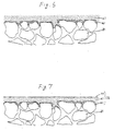
- a second nickel film 61 was formed as shown in Fig. 6.
- Nickel powder having submicron diameter was rubbed into the surface of the second nickel film 61, and pressure of about 700 kg/cm2G was applied to the film, nickel powder having submicron diameter was again rubbed into the surface of the pressed film, and the obtained film was again sintered at 750 °C for 1 hour in a hydrogen atmosphere.
- a third nickel film 71 was formed as shown in Fig. 7.
- platinum (Pt) was laminated on the surface of the third film 71 to be about 200 ⁇ m thickness using sputtering technique. Sputtering was performed using a high frequency sputtering system targeting Pt under 5 x 10 ⁇ 2 mmHg of pressure for 1 hour in an argon (Ar) gas atmosphere.
- the preferred porous substrate it may also be formed of nickel or copper.
- the porous substrate formed of nickel is formed by sintering the nickel powder, the void size of the obtained substrate becomes dispersed in a range of 3 to 50 ⁇ m as irregular surface which is formed according to configuration of nickel powder.
- nickel powder has high adherence to the nickel powder electrode film, it has higher water resistance than a substrate formed of stainless steel.
- the porous substrate can also be formed of copper powder. As the configuration of copper powder is round, configuration of the voids can be rounded and the void size thereof becomes 3 to 40 ⁇ m which is similar to nickel powder.
- the porous substrate using the copper powder becomes an insulator when contacted with oxygen, therefore it cannot be used as the oxygen electrode but is most preferably used as a hydrogen electrode.
- the solidous electrolyte 23 in Fig. 2 is formed as in the following examples;
- a 10 ⁇ m thickness solidous electrolyte film was formed on the Pt coated hydrogen electrode film 22 which was laminated on the porous substrate 21.
- An electron beam sputtering technique was applied to the forming, using a turbo-pump in a vacuum at 10 ⁇ 8 mmHg.
- the temperature of the substrate was varied in a range of ambient to 580 °C, sputtering speed was controlled by a controller.
- the material of the solidous electrolyte single LaF3 crystals were used, the solidous electrolyte film was formed under conditions of 500 °C of substrate temperature, 20 ⁇ /sec of sputtering speed and -3.0 kV of accelerating voltage. Thus, a solidous electrolyte film having no pin holes was obtained.
- a magnetron sputtering technique was applied to the forming, at a 400 °C substrate temperature under a pressure of 5.3 x 10 ⁇ 3 mmHg in an Ar atmosphere. Sputtering was performed over 40 hours using a target of LaF3 powder. A 10 ⁇ m film thickness was obtained. It was concluded from the results of X-ray diffraction tests, that the obtained film was formed an LaF3 polycrystal having poor crystaline quality.
- solidous electrolyte material it is preferrable to use following compounds La 0.95 Sr 0.05 F 2.95 , La 0.95 Sr 0.10 F 2.90 , La 0.95 Ba 0.05 F 2.29 , or La 0.90 Ba 0.10 F 2.29 .
- composition of solidous electrolyte films obtained by sputtering techniques are similar to the composition of the original materials before sputtering even if materials having complex composition are used. Therefore, the sputtering method is preferred to thinner lamination qualities of materials having complex compositions such as La 0.95 Sr 0.05 F 2.95 .
- a metal organic chemical vapor deposition (MOCVD) technique was applied to forming the film of solidous electrolyte.
- Metal organic compounds including La and F in its molecule were heat-decomposed, then the obtained film of LaF3 was laminated on the Pt coated surface of the third nickel film 71 formed on the porous substrate 21 as shown in Fig. 6.
- the structural formula of the compound is following; CF3-CF2-CF2- -CH2- -CH2-(CH3)2 La
- the film forming was accomplished under the following conditions, i.e., the temperature of the substrate was determined at 600°C, the temperature of the metal organic compounds was maintained at 230 °C, with argon gas (Ar) as a carrier gas at flow rate of 100 ml/min. Steam of the metal organic compounds in a reactor was moved to the surface of the porous substrate 21 to react with it, thus a film of LaF3 was obtained.
- argon gas Ar
- a high frequency sputtering technique was applied to forming the film of solidous electrolyte, using a high frequency sputtering system at the temperature of the substrate of 800 °C, under the pressure of Ar at 5.3 x 10 ⁇ 3 mmHg.
- zirconia stabilized by addition of yttria was used for a target. The sputtering was performed over 40 hours, and a 10 ⁇ m thickness of film of solidous electrolyte having no pin holes was obtained thereafter.
- Compounds such as cerium oxide may also be used.
- the oxygen electrode film 24 is formed as in the following examples.
- the oxygen electrode film was formed of perovskite compound.
- a perovskite compound of La 0.6 Sr 0.4 CoO x was obtained by mixing powder of cobalt acetate (CH3COO)2CO 4H2O, lanthanum acetate (CH3COO)2La and strontium acetate (CH3COO)2Sr, which amounts thereof were weighed corresponding to a composition ratio of La 0.6 Sr 0.4 CoO x .
- the mixture of powder as above described was baked at 1000 °C for 5 hours in an oxygen atmosphere.
- the electric resistance ratio of the obtained perovskite compound was 4.4 ohm ⁇ cm.
- the perovskite compound was dissolved in propylene glycol, then this solution was applied to the surface of the solidous electrolyte film 23, baked under pressure at 300 °C for 8 hours in an oxygen atmosphere over 8 hours.
- an oxygen electrode film 24 as shown in Fig. 2 was obtained.
- a perovskite compound was formed as shown in Example 7.
- the obtained compound was mixed with platinum black at a ratio of 3:1, then dissolved in propylene glycol.
- the mixture was applied to the surface of the solidous electrolyte film 23, then baked under the same conditions described in Example 7, thus an oxygen electrode film 24 was obtained.
- a perovskite compound was formed as shown in Example 7.
- the obtained compound was then sputtered on the surface of the solidous electrolyte film 23 using a high frequency sputtering system.
- the sputtering was accomplished in an Ar atmosphere under a pressure of 1 x 10 ⁇ 2 mmHg, at 0.5 ⁇ m/hour sputtering speed for 2 hours, thus about a 1 ⁇ m thickness of oxygen electrode film 24 was obtained.
- the perovskite compound as above mentioned has similar characteristics to platinum but is greatly less expensive.
- the porous substrate, the hydrogen electrode film, the solidous electrolyte film, and the oxygen electrode film formed as previously described are stacked sequentially to form a cell unit structure.
- the cell unit is installed in a cell casing 25 having conductivity to electrically connect the hydrogen electrode film 22 of the cell unit with the casing 25.
- the oxygen electrode film 24 is connected electrically with a separator 27 which is adhered to the cathode side.
- a insulator 26 is installed between the cell casing 25 and the separator 27.
- a conductive separator 27′ is connected electrically with the cell casing 25 concurrently with the oxygen electrode film 24′ at both sides of the separator 27′.
- a insulator 26′ is installed between the separator 27′ and the casing 25′, thus a fuel cell body 40b is constructed and stacked with the cell body 40a.
- fuel cell bodies 40c, 40d...(not shown in Fig. 2) are constructed and stacked sequentially. Therefore, a plurality of the cell units can be stacked connected in series. Oxygen, as an oxidant, is provided from gas inducing paths 29 and 29′ to the cells, and hydrogen as fuel is provided from gas inducing paths 30 and 30′ to the cells, thus, electric power is produced.
- the hydrogen electrode is formed of fine powder mixture of nickel then sintered, void sizes can be homogenized.
- formation of pin holes on the films laminated on the electrode can be avoided even if a very thin solidous electrolyte film is laminated. Accordingly, voltage dropping can be reduced by reducing the thickness of the solidous electrolyte.
Landscapes
- Chemical & Material Sciences (AREA)
- Chemical Kinetics & Catalysis (AREA)
- Engineering & Computer Science (AREA)
- General Chemical & Material Sciences (AREA)
- Electrochemistry (AREA)
- Manufacturing & Machinery (AREA)
- Sustainable Energy (AREA)
- Life Sciences & Earth Sciences (AREA)
- Sustainable Development (AREA)
- Materials Engineering (AREA)
- Mechanical Engineering (AREA)
- Metallurgy (AREA)
- Organic Chemistry (AREA)
- Physics & Mathematics (AREA)
- Thermal Sciences (AREA)
- Inorganic Chemistry (AREA)
- Fuel Cell (AREA)
- Inert Electrodes (AREA)
Abstract
Description
- The present invention relates generally to a fuel cell utilizing solidous electrolyte. Specifically, the present invention relates to a fuel cell which is composed of stacking solidous electrolyte thin film and a process for forming same.
- Fuel cells, such as plate type fuel cells are well known cell products utilizing porous substrates.
- Generally, fuel cells for the production of electrical energy from a fuel and oxidant are well known in the art. Simply put, such cells are composed of a plurality of cell unit structures comprising sequentially stacked porous substrate, an anode electrode film, an electrolyte layer and a cathode electrode film, the cell units are connected in series. Hydrogen gas as fuel is provided in the cathode side of the fuel cell body and air (Oxygen gas) as oxidant is provided in the anode side thereof, then hydrogen and oxygen are reacted for producing electromotive force and water as a by-product. The electrolyte can be a solid, a molten paste, a free-flowing liquid, or a liquid trapped in a matrix. This invention is concerned with the solid type of electrolyte which is preferred for many applications.
- It is also well known in the art that voltage dropping in a solidous electrolyte may be indicated by following formula:
V = iRt x 10⁻⁴
wherein V : voltage dropping
i : electric current (A)
R : resistance (ohm·cm)
t : thickness of solidous electrolyte (µm)
- From the above relationship, voltage dropping of fuel cell can be reduced corresponding to reducing the thickness of the solidous electrolyte. On the other hand, as a solidous electrolyte is formed on a thin electrode film over the porous substrate, the thickness of the electrolyte is determined by its coverage ability but must be thick enough to support a stacked cell structure, therefore, thinner is better but the minimum thickness is restricted. In view of these points, it has been assumed that thickness in a range of 10 to 50 µm is preferrable for a solidous electrolyte layer.
- Porous substrates generally in use have dispersed void sizes in a range of 0.5 to 40 µm. Numbers of pin holes are formed in both the electrode film and the solidous electrolyte where it is stacked on portions of the substrate having relatively large void sizes, when the thin electrode film with the solidous electrolyte are stacked on the substrate.
- As well known in the art, electromotive force is produced at both sides of the solidous electrolyte when a concentration difference is created by a partial pressure difference of oxygen at each side. That is, the partial pressure difference forms a kind of concentration cell. The electromotive force of a fuel cell may be derived by the following formula:
E₀ = (RT/4F) x 1n(P₁/P₂)
wherein R : gas constant
T : absolute temperature
F : Faraday constant
P₁,P₂ : partial pressure of oxygen at both sides of the solidous electrolyte - As shown in the above formula, electromotive force E₀ proportionally increases corresponding to the ratio of the oxygen partial pressure. Therefore, any pin holes formed in the solidous electrolyte reduces the partial pressure difference of oxygen to zero, it causes loss of electromotive force or may even make the production thereof impossible. Avoid the formation of pin holes is greatly important for forming fuel cells.
- It is therefore the principal object of the present invention to provide a fuel cell utilizing solidous electrolyte inducing a minimum of voltage drop.
- It is another object of the present invention to provide a fuel cell utilizing a thin solidous electrolyte in which the electrode surface to which the electrolyte is applied has fine voids of homogeneous diameter.
- It is a further object of the present invention to provide a fuel cell utilizing solidous electrolyte which is free from pin holes.
- It is a furthermore object of the present invention to provide a method for forming a fuel cell utilizing thin film of solidous electrolyte.
- A fuel cell constructed of a plurality of cell unit structures stacked and connected in series, wherein the cell unit structure is composed of,
a porous substrate,
a hydrogen electrode film stacked on the porous substrate, the hydrogen electrode formed of fine particles of nickel powder having fine voids of homogeneous diameter,
a solidous electrolyte film stacked on the hydrogen electrode film, and
an oxygen electrode film stacked on the solidous electrolyte film. - A process for forming the above-mentioned fuel cell, wherein the cell unit structure is formed by a process comprising the steps of: preparing a porous substrate for a base of the cell unit structure,
stacking a hydrogen electrode thin film having fine voids of homogeneous diameter on the porous substrate, wherein the film is formed by pressing a mixture of fine particles of nickel powder then sintering the mixture,
stacking a solidous electrolyte film on the hydrogen electrode film, and
stacking an oxygen electrode film on the solidous electrolyte film. - The present invention will be understood from the detailed description given hereinbelow and from the accompanying drawings of the preferred embodiments which are given for explanation and understanding only and are not intended to imply limitation to the invention.
- In the drawings;
- Fig. 1 is a plan view of a conventional stacked cell;
- Fig. 2 is a partial longitudinal sectional view of stacked unit structures of a conventionally used fuel cell;
- Figs. 3 to 7 are enlarged cross sectional views showing a process of forming a thin film for a hydrogen electrode according to a procedure of the present invention.
- The present invention will now be described in detail referring to the accompanying drawings.
- Referring now to Fig. 1, a fuel cell body 10 is composed of a plurality of cell unit structures S, a pair of
fixing plates 11a and 11b to connect the stacked cell units S in series, ahydrogen path 12 for providing hydrogen to a cathode plate side of each cell unit S, anoxygen path 13 for providing oxygen to an anode plate side of each cell unit S, and a pair oflead lines 14 and 15 to collect electric power from the cathode and the anode sides of each cell unit S. Bothpaths lead lines 14 and 15 are installed on the outside or each cell unit S. - Electric power and water (as a by-product) are produced when hydrogen gas and air (oxygen gas), provided respectively, react through an electrolyte, then electric power produced is collected by the
lead lines 14 and 15. - Fig. 2 is an enlarged longitudinal sectional view of stacked fuel cell bodies as shown in Fig. 1 which utilize a type of solidous electrolyte. A cell unit is composed of a lamination of a
porous substrate 21 formed of stainless steel, a hydrogen electrode film (a first electrode film) 22, asolidous electrolyte film 23, and an oxygen electrode film (a second electrode film) 24, which are laminated sequentially. - The
hydrogen electrode film 22 is formed on theporous substrate 21 as in the following example; - As the porous substrate for the base of the hydrogen electrode, SUS316L (JIS standard) having about 40% of void ratio, 0.5 µm of nominated void size and about 1 mm of thickness was used. Although the nominated void size is indicated as 0.5 µm, the actual void sizes are dispersed in a certain range, there are many voids having about 10 µm, sometimes up to about 40 µm.
- The
porous substrate 21 was punched to a disc having 0.5 inch of diameter, then the disc was subjected to ultrasonic cleaning in a trichlene solution followed by drying. The obtained substrate is shown in Fig. 3 diagramatically. - Then nickel powder having a particle diameter of less than or equal to 1 µm (hereinafter, submicron diameter) and nickel powder having particle diameter of 3 µm were mixed at a volume ratio of 1 : 1, and dissolved in water. The solution of the nickel powder mixture was applied uniformly on the
porous substrate 21 as shown in Fig. 4. The applied solution was dried at ambient temperature, then sintered at 1000 °C for 1 hour in a hydrogen atmosphere. Thus, afirst nickel film 41 was formed. - The surface of the
first nickel film 41 was polished as shown in Fig. 5, to remove projections therefrom. As an agent for the polishing, a #600 grit paper was used. Thepolished nickel film 41 was subjected to ultrasonic cleaning in deionized water and trichloroethylene solution for 10 min, the cleaned film was thereafter dried at ambient temperature. Then about 50 mg of nickel powder having a particle diameter of 3 µm was applied uniformly to the surface of thefirst nickel film 41 of theporous substrate 21, a pressure of about 700 kg/cm²G was applied to the film, and the newly obtained film was sintered at 750 °C for 1 hour in a hydrogen atmosphere. Thus, a second nickel film 61 was formed as shown in Fig. 6. - Nickel powder having submicron diameter was rubbed into the surface of the second nickel film 61, and pressure of about 700 kg/cm²G was applied to the film, nickel powder having submicron diameter was again rubbed into the surface of the pressed film, and the obtained film was again sintered at 750 °C for 1 hour in a hydrogen atmosphere. Thus, a third nickel film 71 was formed as shown in Fig. 7.
- According to the above procedure, a
hydrogen electrode film 22 having thickness of about 100 µm which was composed of thefirst nickel film 41, the second nickel film 61 and the third nickel film 71 laminated sequentially on the surface of theporous substrate 21, was obtained. Voids having diameter of 1 to 3 µm opened uniformly at the top surface thereof. - After forming the third nickel film 71, platinum (Pt) was laminated on the surface of the third film 71 to be about 200 µm thickness using sputtering technique. Sputtering was performed using a high frequency sputtering system targeting Pt under 5 x 10 ⁻² mmHg of pressure for 1 hour in an argon (Ar) gas atmosphere.
- Coating of the surface of the third nickel film 71 by Pt is effective for promoting a reaction at the electrode indicated as follows, because Pt acts as catalyst;
O²⁻ + H₂ = H₂O + 2e⁻
Therefore, high electric power can be produced easily and quickly in the cell when coating of Pt is applied. - Further to say, as the preferred porous substrate, it may also be formed of nickel or copper. The porous substrate formed of nickel is formed by sintering the nickel powder, the void size of the obtained substrate becomes dispersed in a range of 3 to 50 µm as irregular surface which is formed according to configuration of nickel powder. As nickel powder has high adherence to the nickel powder electrode film, it has higher water resistance than a substrate formed of stainless steel. Alternatively, the porous substrate can also be formed of copper powder. As the configuration of copper powder is round, configuration of the voids can be rounded and the void size thereof becomes 3 to 40 µm which is similar to nickel powder. The porous substrate using the copper powder becomes an insulator when contacted with oxygen, therefore it cannot be used as the oxygen electrode but is most preferably used as a hydrogen electrode.
- The
solidous electrolyte 23 in Fig. 2 is formed as in the following examples; - A 10 µm thickness solidous electrolyte film was formed on the Pt coated
hydrogen electrode film 22 which was laminated on theporous substrate 21. An electron beam sputtering technique was applied to the forming, using a turbo-pump in a vacuum at 10⁻⁸ mmHg. The temperature of the substrate was varied in a range of ambient to 580 °C, sputtering speed was controlled by a controller. As the material of the solidous electrolyte, single LaF₃ crystals were used, the solidous electrolyte film was formed under conditions of 500 °C of substrate temperature, 20 Å/sec of sputtering speed and -3.0 kV of accelerating voltage. Thus, a solidous electrolyte film having no pin holes was obtained. - Resistance heating was applied to the forming, using a turbo-pump as mentioned in the first procedure in a vacuum at 10⁻⁸ mmHg. The temperature of the substrate was determined at 400°C, with a sputtering speed of 3 to 5 Å/sec. The forming was performed over about 5 to 6 hours. A 10 µm thickness solidous electrolyte film having no pin holes was obtained. La1-xSrF3-x can also be used as material for the solidous electrolyte. When X-ray diffraction was applied to the film obtained from La0.95Sr0.95F2.95, only a peak of LaF₃ was found. From this result, the obtained film of solidous electrolyte was not formed of a mixture of LaF₃ and SrF₂ but only of LaF₃.
- A magnetron sputtering technique was applied to the forming, at a 400 °C substrate temperature under a pressure of 5.3 x 10 ⁻³ mmHg in an Ar atmosphere. Sputtering was performed over 40 hours using a target of LaF₃ powder. A 10 µm film thickness was obtained. It was concluded from the results of X-ray diffraction tests, that the obtained film was formed an LaF₃ polycrystal having poor crystaline quality.
- As the solidous electrolyte material it is preferrable to use following compounds La0.95Sr0.05F2.95, La0.95Sr0.10F2.90, La0.95Ba0.05F2.29, or La0.90Ba0.10F2.29.
- The composition of solidous electrolyte films obtained by sputtering techniques are similar to the composition of the original materials before sputtering even if materials having complex composition are used. Therefore, the sputtering method is preferred to thinner lamination qualities of materials having complex compositions such as La0.95Sr0.05F2.95.
- A metal organic chemical vapor deposition (MOCVD) technique was applied to forming the film of solidous electrolyte. Metal organic compounds including La and F in its molecule were heat-decomposed, then the obtained film of LaF₃ was laminated on the Pt coated surface of the third nickel film 71 formed on the
porous substrate 21 as shown in Fig. 6. The structural formula of the compound is following;
CF₃-CF₂-CF₂--CH₂- -CH₂-(CH₃)₂ La
The film forming was accomplished under the following conditions, i.e., the temperature of the substrate was determined at 600°C, the temperature of the metal organic compounds was maintained at 230 °C, with argon gas (Ar) as a carrier gas at flow rate of 100 ml/min. Steam of the metal organic compounds in a reactor was moved to the surface of theporous substrate 21 to react with it, thus a film of LaF₃ was obtained. - A high frequency sputtering technique was applied to forming the film of solidous electrolyte, using a high frequency sputtering system at the temperature of the substrate of 800 °C, under the pressure of Ar at 5.3 x 10⁻³ mmHg. For a target, zirconia stabilized by addition of yttria was used. The sputtering was performed over 40 hours, and a 10 µm thickness of film of solidous electrolyte having no pin holes was obtained thereafter. Compounds such as cerium oxide may also be used.
- The
oxygen electrode film 24 is formed as in the following examples; - The oxygen electrode film was formed of perovskite compound. A perovskite compound of La0.6Sr0.4CoOx was obtained by mixing powder of cobalt acetate (CH₃COO)₂CO 4H₂O, lanthanum acetate (CH₃COO)₂La and strontium acetate (CH₃COO)₂Sr, which amounts thereof were weighed corresponding to a composition ratio of La0.6Sr0.4CoOx. The mixture of powder as above described was baked at 1000 °C for 5 hours in an oxygen atmosphere. The electric resistance ratio of the obtained perovskite compound was 4.4 ohm·cm.
- The perovskite compound was dissolved in propylene glycol, then this solution was applied to the surface of the
solidous electrolyte film 23, baked under pressure at 300 °C for 8 hours in an oxygen atmosphere over 8 hours. Thus, anoxygen electrode film 24 as shown in Fig. 2 was obtained. - A perovskite compound was formed as shown in Example 7.
- The obtained compound was mixed with platinum black at a ratio of 3:1, then dissolved in propylene glycol. The mixture was applied to the surface of the
solidous electrolyte film 23, then baked under the same conditions described in Example 7, thus anoxygen electrode film 24 was obtained. - A perovskite compound was formed as shown in Example 7.
- The obtained compound was then sputtered on the surface of the
solidous electrolyte film 23 using a high frequency sputtering system. The sputtering was accomplished in an Ar atmosphere under a pressure of 1 x 10⁻² mmHg, at 0.5 µm/hour sputtering speed for 2 hours, thus about a 1 µm thickness ofoxygen electrode film 24 was obtained. - The perovskite compound as above mentioned has similar characteristics to platinum but is greatly less expensive.
- Ag powder was dissolved in propylene glycol then the obtained solution was applied to the surface of the
solidous electrolyte film 23. The film was baked under pressure at 300 °C in an oxygen atmosphere for 8 hours. Thus, anoxygen electrode film 24 was obtained. - Chloroplatinic acid (H₂PtCl₆) was dissolved in propylene glycol. The obtained solution was treated as described in Example 10, thus, an
oxygen electrode film 24 was obtained. - Referring now again to Fig. 2, the porous substrate, the hydrogen electrode film, the solidous electrolyte film, and the oxygen electrode film formed as previously described are stacked sequentially to form a cell unit structure. The cell unit is installed in a
cell casing 25 having conductivity to electrically connect thehydrogen electrode film 22 of the cell unit with thecasing 25. Concurrently, theoxygen electrode film 24 is connected electrically with aseparator 27 which is adhered to the cathode side. Ainsulator 26 is installed between thecell casing 25 and theseparator 27. Thus, afuel cell body 40a is constructed. At the side of theporous substrate 21 of thecell body 40a, aconductive separator 27′ is connected electrically with thecell casing 25 concurrently with theoxygen electrode film 24′ at both sides of theseparator 27′. Ainsulator 26′ is installed between theseparator 27′ and thecasing 25′, thus afuel cell body 40b is constructed and stacked with thecell body 40a. Similarly, fuel cell bodies 40c, 40d...(not shown in Fig. 2) are constructed and stacked sequentially. Therefore, a plurality of the cell units can be stacked connected in series. Oxygen, as an oxidant, is provided fromgas inducing paths gas inducing paths - According to the present invention, as the hydrogen electrode is formed of fine powder mixture of nickel then sintered, void sizes can be homogenized. Thus, formation of pin holes on the films laminated on the electrode can be avoided even if a very thin solidous electrolyte film is laminated. Accordingly, voltage dropping can be reduced by reducing the thickness of the solidous electrolyte.
- While the present invention has been disclosed in terms of the preferred embodiment in order to facilitate better understanding thereof, it should be appreciated that the invention can be embodied in various ways without departing from the principles thereof. Therefore, the invention should be understood to include all possible embodiments and modifications to shown embodiments which can be embodied without departing from the principle of the invention as set out in the appended claims.
Claims (36)
a porous substrate,
a hydrogen electrode film stacked on the porous substrate, said hydrogen electrode formed of fine particles of nickel powder having fine voids of homogeneous diameter,
a solidous electrolyte film stacked on the hydrogen electrode film, and
an oxygen electrode film stacked on the solidous electrolyte film.
a porous substrate,
a hydrogen electrode film stacked on the porous substrate, said hydrogen electrode formed of fine particles of nickel powder having fine voids of homogeneous diameter,
a coating of platinum stacked on the hydrogen electrode film,
a solidous electrolyte film stacked on the platinum coated, and
an oxygen electrode film stacked on the solidous electrolyte film.
a porous substrate,
a hydrogen electrode film stacked on said porous substrate, said film formed of a mixture of a first nickel powder having diameter of less than or equal to 1 µm and a second nickel powder having diameter of less than or equal to 3 µm, for forming fine voids of homogeneous diameter,
a coating of platinum stacked on said hydrogen electrode film,
a solidous electrolyte film stacked on said platinum coating, and
an oxygen electrode film stacked on said solidous electrolyte film.
preparing a porous substrate for a base of said cell unit structure,
stacking a hydrogen electrode film having fine voids of homogeneous diameter on said porous substrate, wherein the film is formed by pressing a mixture of fine particles of nickel powder then sintering the mixture,
stacking a solidous electrolyte film on the hydrogen electrode film, and
stacking an oxygen electrode film on the solidous electrolyte film.
preparing a porous substrate for a base of said cell unit structure,
stacking a hydrogen electrode film having fine voids of homogeneous diameter on said porous substrate, wherein the film is formed by pressing a mixture of fine particles of nickel powder then sintering the mixture,
sputtering platinum on the hydrogen electrode film to form a platinum coating,
stacking a solidous electrolyte film on the platinum coating, and
stacking an oxygen electrode film on the solidous electrolyte film.
preparing a porous substrate for a base of said cell unit structure,
stacking a hydrogen electrode film having fine voids of homogeneous diameter on said porous substrate, wherein said film is formed by pressing a mixture of a first nickel powder having diameter of less than or equal to 1 µm and a second nickel powder having diameter of less than or equal to 3 µm, then sintering said pressed mixture,
sputtering platinum on said hydrogen electrode film to form a platinum coating,
stacking a solidous electrolyte film on said platinum coating, and
stacking an oxygen electrode film on said solidous electrolyte film.
pressing and sintering a first nickel powder,
polishing said sintered first nickel powder to form a first nickel film,
applying a second nickel powder to said first nickel film and pressing then sintering said second nickel powder to form a second nickel film, and
rubbing a nickel powder having a diameter of said first nickel powder into a surface of said second nickel film and pressing then sintering thereof to form a third nickel film having three layers.
Applications Claiming Priority (4)
| Application Number | Priority Date | Filing Date | Title |
|---|---|---|---|
| JP1217780A JP2940008B2 (en) | 1989-08-24 | 1989-08-24 | Solid oxide fuel cell |
| JP1217777A JP2841528B2 (en) | 1989-08-24 | 1989-08-24 | Solid oxide fuel cell |
| JP217780/89 | 1989-08-24 | ||
| JP217777/89 | 1989-08-24 |
Publications (3)
| Publication Number | Publication Date |
|---|---|
| EP0414270A2 true EP0414270A2 (en) | 1991-02-27 |
| EP0414270A3 EP0414270A3 (en) | 1991-11-13 |
| EP0414270B1 EP0414270B1 (en) | 1995-02-15 |
Family
ID=26522200
Family Applications (1)
| Application Number | Title | Priority Date | Filing Date |
|---|---|---|---|
| EP90116284A Expired - Lifetime EP0414270B1 (en) | 1989-08-24 | 1990-08-24 | Fuel cell utilizing solidous electrolyte |
Country Status (4)
| Country | Link |
|---|---|
| US (1) | US5151334A (en) |
| EP (1) | EP0414270B1 (en) |
| KR (1) | KR950001256B1 (en) |
| DE (1) | DE69016881T2 (en) |
Cited By (13)
| Publication number | Priority date | Publication date | Assignee | Title |
|---|---|---|---|---|
| EP0466418A1 (en) * | 1990-07-07 | 1992-01-15 | Ngk Insulators, Ltd. | Solid oxide fuel cell and porous electrode for use in the same |
| EP0607651A1 (en) * | 1993-01-15 | 1994-07-27 | General Electric Company | Prevention of fuel thermal degradation deposits |
| EP0608081A1 (en) * | 1993-01-15 | 1994-07-27 | General Electric Company | Coated articles and method for the prevention of fuel thermal degradation deposits |
| EP0635896A1 (en) * | 1993-07-20 | 1995-01-25 | Sulzer Innotec Ag | Centrally symmetric fuel cell battery |
| WO1997023007A3 (en) * | 1995-12-20 | 1997-07-31 | Forschungszentrum Juelich Gmbh | Electrode substrate for fuel cell |
| WO1997030485A1 (en) * | 1996-02-12 | 1997-08-21 | Siemens Aktiengesellschaft | High-temperature fuel cell and high-temperature fuel cell stack with metallic composite conducting structures |
| WO1997034333A1 (en) * | 1996-03-11 | 1997-09-18 | Forschungszentrum Jülich GmbH | Coating of porous electrodes with thin electrolyte layers |
| US5805973A (en) * | 1991-03-25 | 1998-09-08 | General Electric Company | Coated articles and method for the prevention of fuel thermal degradation deposits |
| EP1122806A1 (en) * | 2000-02-02 | 2001-08-08 | Haldor Topsoe A/S | Solid oxide fuel cell |
| WO2005045963A3 (en) * | 2003-11-05 | 2006-07-06 | Honda Motor Co Ltd | Electrolyte-electrode joined assembly and method for producing the same |
| WO2006018568A3 (en) * | 2004-07-21 | 2007-04-05 | Saint Gobain | Non-oxidised electrolyte electrochemical system |
| EP1225648A3 (en) * | 2001-01-17 | 2007-09-05 | Nissan Motor Co., Ltd. | Solid oxide fuel cell |
| US7449214B2 (en) | 2002-03-27 | 2008-11-11 | Haldor Topsoe A/S | Process for the preparation of solid oxide fuel cell |
Families Citing this family (24)
| Publication number | Priority date | Publication date | Assignee | Title |
|---|---|---|---|---|
| JP3295945B2 (en) * | 1991-02-22 | 2002-06-24 | 株式会社村田製作所 | Distributor of solid oxide fuel cell and method of manufacturing the same |
| US5372895A (en) * | 1991-12-12 | 1994-12-13 | Yoshida Kogyo K.K. | Solid oxide fuel cell and method for manufacturing the same |
| DE4318818C2 (en) * | 1993-06-07 | 1995-05-04 | Daimler Benz Ag | Method and device for providing conditioned process air for air-breathing fuel cell systems |
| US5942348A (en) * | 1994-12-01 | 1999-08-24 | Siemens Aktiengesellschaft | Fuel cell with ceramic-coated bipolar plates and a process for producing the fuel cell |
| US6153327A (en) * | 1995-03-03 | 2000-11-28 | Southwest Research Institute | Amorphous carbon comprising a catalyst |
| US6159533A (en) * | 1997-09-11 | 2000-12-12 | Southwest Research Institute | Method of depositing a catalyst on a fuel cell electrode |
| US5939219A (en) * | 1995-10-12 | 1999-08-17 | Siemens Aktiengesellschaft | High-temperature fuel cell having at least one electrically insulating covering and method for producing a high-temperature fuel cell |
| EP0788175B1 (en) * | 1996-02-02 | 2000-04-12 | Sulzer Hexis AG | High temperature fuel cell with an electrolyte thin film |
| AU3137097A (en) | 1996-05-16 | 1997-12-05 | Lockheed Martin Energy Systems, Inc. | Low temperature material bonding technique |
| US6001500A (en) * | 1996-06-05 | 1999-12-14 | Southwest Res Inst | Cylindrical proton exchange membrane fuel cells and methods of making same |
| US6063517A (en) * | 1997-10-16 | 2000-05-16 | Southwest Research Institute | Spiral wrapped cylindrical proton exchange membrane fuel cells and methods of making same |
| US5902691A (en) * | 1997-10-27 | 1999-05-11 | Ut Automotive Dearborn, Inc. | Fuel cell with shared space for electrode assembly |
| US6051329A (en) * | 1998-01-15 | 2000-04-18 | International Business Machines Corporation | Solid oxide fuel cell having a catalytic anode |
| US6096450A (en) * | 1998-02-11 | 2000-08-01 | Plug Power Inc. | Fuel cell assembly fluid flow plate having conductive fibers and rigidizing material therein |
| US6610436B1 (en) * | 1998-09-11 | 2003-08-26 | Gore Enterprise Holdings | Catalytic coatings and fuel cell electrodes and membrane electrode assemblies made therefrom |
| US6287717B1 (en) | 1998-11-13 | 2001-09-11 | Gore Enterprise Holdings, Inc. | Fuel cell membrane electrode assemblies with improved power outputs |
| US6228521B1 (en) * | 1998-12-08 | 2001-05-08 | The University Of Utah Research Foundation | High power density solid oxide fuel cell having a graded anode |
| US6300000B1 (en) | 1999-06-18 | 2001-10-09 | Gore Enterprise Holdings | Fuel cell membrane electrode assemblies with improved power outputs and poison resistance |
| AU2003291044A1 (en) * | 2002-11-15 | 2004-06-15 | Battelle Memorial Institute | Copper-substituted perovskite compositions for solid oxide fuel cell cathodes and oxygen reduction electrochemical devices |
| US20040214070A1 (en) * | 2003-04-28 | 2004-10-28 | Simner Steven P. | Low sintering lanthanum ferrite materials for use as solid oxide fuel cell cathodes and oxygen reduction electrodes and other electrochemical devices |
| JP4551429B2 (en) * | 2006-09-29 | 2010-09-29 | 株式会社神戸製鋼所 | Method for manufacturing fuel cell separator, fuel cell separator and fuel cell |
| US9070946B2 (en) * | 2010-01-19 | 2015-06-30 | Honda Motor Co., Ltd. | Electrolyte-electrode joined assembly and method for producing the same |
| KR101288407B1 (en) * | 2012-03-12 | 2013-07-22 | 전북대학교산학협력단 | Manufacturing method of anode for solid oxide fuel cell and anode for solid oxide fuel cell manufactured thereby |
| BR112014031304A2 (en) | 2012-06-13 | 2017-06-27 | Nuvera Fuel Cells Inc | flow structure for use in electrochemical cell, respective manufacturing method and electrochemical cell |
Family Cites Families (11)
| Publication number | Priority date | Publication date | Assignee | Title |
|---|---|---|---|---|
| US3464861A (en) * | 1964-08-20 | 1969-09-02 | Shell Oil Co | Fuel cells with solid state electrolytes |
| LU56788A1 (en) * | 1967-08-31 | 1968-11-22 | ||
| US3551209A (en) * | 1969-05-21 | 1970-12-29 | Us Interior | Formation of skeletal metal solid electrolyte fuel cell electrodes |
| CH515622A (en) * | 1969-10-22 | 1971-11-15 | Raffinage Cie Francaise | High-temp solid electrolyte fuel cell - with composite electrode/elec |
| FR2182650B1 (en) * | 1972-04-27 | 1974-07-26 | Citroen Sa | |
| DE2316067C3 (en) * | 1973-03-30 | 1979-04-12 | Siemens Ag, 1000 Berlin Und 8000 Muenchen | Fuel battery in feed press design |
| US4129685A (en) * | 1977-08-15 | 1978-12-12 | United Technologies Corp. | Fuel cell structure |
| JPS62268063A (en) * | 1986-05-14 | 1987-11-20 | Mitsubishi Heavy Ind Ltd | Solid electrolyte manufacturing method |
| JPS6353863A (en) * | 1986-08-22 | 1988-03-08 | Mitsubishi Heavy Ind Ltd | Solid electrolytic fuel cell |
| US4851303A (en) * | 1986-11-26 | 1989-07-25 | Sri-International | Solid compositions for fuel cells, sensors and catalysts |
| JPH02504445A (en) * | 1988-05-20 | 1990-12-13 | エス・アール・アイ・インターナシヨナル | Solid compositions for fuel cell electrolytes |
-
1990
- 1990-08-23 KR KR1019900013022A patent/KR950001256B1/en not_active Expired - Fee Related
- 1990-08-24 US US07/573,245 patent/US5151334A/en not_active Expired - Fee Related
- 1990-08-24 DE DE69016881T patent/DE69016881T2/en not_active Expired - Fee Related
- 1990-08-24 EP EP90116284A patent/EP0414270B1/en not_active Expired - Lifetime
Cited By (19)
| Publication number | Priority date | Publication date | Assignee | Title |
|---|---|---|---|---|
| EP0466418A1 (en) * | 1990-07-07 | 1992-01-15 | Ngk Insulators, Ltd. | Solid oxide fuel cell and porous electrode for use in the same |
| US5805973A (en) * | 1991-03-25 | 1998-09-08 | General Electric Company | Coated articles and method for the prevention of fuel thermal degradation deposits |
| EP0607651A1 (en) * | 1993-01-15 | 1994-07-27 | General Electric Company | Prevention of fuel thermal degradation deposits |
| EP0608081A1 (en) * | 1993-01-15 | 1994-07-27 | General Electric Company | Coated articles and method for the prevention of fuel thermal degradation deposits |
| US5418079A (en) * | 1993-07-20 | 1995-05-23 | Sulzer Innotec Ag | Axially symmetric fuel cell battery |
| EP0635896A1 (en) * | 1993-07-20 | 1995-01-25 | Sulzer Innotec Ag | Centrally symmetric fuel cell battery |
| WO1997023007A3 (en) * | 1995-12-20 | 1997-07-31 | Forschungszentrum Juelich Gmbh | Electrode substrate for fuel cell |
| WO1997030485A1 (en) * | 1996-02-12 | 1997-08-21 | Siemens Aktiengesellschaft | High-temperature fuel cell and high-temperature fuel cell stack with metallic composite conducting structures |
| AU718046B2 (en) * | 1996-02-12 | 2000-04-06 | Siemens Aktiengesellschaft | High-temperature fuel cell and high-temperature fuel cell stack |
| US6156448A (en) * | 1996-02-12 | 2000-12-05 | Siemens Aktiengesellschaft | High temperature fuel cell and high temperature fuel cell stack |
| WO1997034333A1 (en) * | 1996-03-11 | 1997-09-18 | Forschungszentrum Jülich GmbH | Coating of porous electrodes with thin electrolyte layers |
| EP1122806A1 (en) * | 2000-02-02 | 2001-08-08 | Haldor Topsoe A/S | Solid oxide fuel cell |
| US6783880B2 (en) | 2000-02-02 | 2004-08-31 | Haldor Topsoe A/S | Porous planar electrode support in a solid oxide fuel cell |
| EP1225648A3 (en) * | 2001-01-17 | 2007-09-05 | Nissan Motor Co., Ltd. | Solid oxide fuel cell |
| US7326484B2 (en) | 2001-01-17 | 2008-02-05 | Nissan Motor Co., Ltd. | Solid oxide fuel cell |
| US7449214B2 (en) | 2002-03-27 | 2008-11-11 | Haldor Topsoe A/S | Process for the preparation of solid oxide fuel cell |
| WO2005045963A3 (en) * | 2003-11-05 | 2006-07-06 | Honda Motor Co Ltd | Electrolyte-electrode joined assembly and method for producing the same |
| US7300718B2 (en) | 2003-11-05 | 2007-11-27 | Honda Motor Co., Ltd. | Electrolyte-electrode joined assembly and method for producing the same |
| WO2006018568A3 (en) * | 2004-07-21 | 2007-04-05 | Saint Gobain | Non-oxidised electrolyte electrochemical system |
Also Published As
| Publication number | Publication date |
|---|---|
| DE69016881D1 (en) | 1995-03-23 |
| US5151334A (en) | 1992-09-29 |
| KR950001256B1 (en) | 1995-02-15 |
| KR910005504A (en) | 1991-03-30 |
| EP0414270A3 (en) | 1991-11-13 |
| DE69016881T2 (en) | 1995-06-08 |
| EP0414270B1 (en) | 1995-02-15 |
Similar Documents
| Publication | Publication Date | Title |
|---|---|---|
| EP0414270A2 (en) | Fuel cell utilizing solidous electrolyte | |
| DE69607967T2 (en) | ELECTROCATALYTICAL STRUCTURE WITH A MATRIX MADE OF SiOxCyHz AND EMBEDDED PARTICLES MADE OF CATALYTICALLY ACTIVE MATERIAL | |
| Peuckert et al. | Oxygen reduction on small supported platinum particles | |
| EP1402951A1 (en) | Conductive catalyst particle and its manufacturing method, gas-diffusing catalyst electrode, and electrochemical device | |
| US6319626B1 (en) | Cathode composition for solid oxide fuel cell | |
| US5441822A (en) | Electrode used in electrochemical reaction and fuel cell using the same | |
| CA2341495C (en) | Gas diffusion electrode and method for its production | |
| KR20020092930A (en) | Suboxide Fuel Cell Catalyst for Enhanced Reformate Tolerance | |
| JPH0652862A (en) | Porous electrode and its manufacture | |
| US6548203B2 (en) | Cathode composition for solid oxide fuel cell | |
| US8053135B2 (en) | Microporous thin film comprising nanoparticles, method of forming the same, and fuel cell comprising the same | |
| US20090035640A1 (en) | Catalyst-loaded support used for forming electrode for fuel cell, and method of producing the same | |
| JP2010218923A (en) | Platinum oxide catalyst for fuel cell | |
| JPH07503657A (en) | Electrochemical cells and their use in electrochemical separation and extraction of oxygen | |
| US8518606B2 (en) | Catalyst thin layer and method for fabricating the same | |
| US7700219B2 (en) | Structure having three-dimensional network skeleton, method for producing the structure, and fuel cell including the structure | |
| JP2841528B2 (en) | Solid oxide fuel cell | |
| JP3442408B2 (en) | Method for producing electrode-electrolyte assembly and fuel cell using the same | |
| EP0519681B1 (en) | Method for preparing anode for solid oxide fuel cells | |
| JP2947495B2 (en) | Fuel electrode fabrication method for solid oxide fuel cells | |
| RU2128384C1 (en) | Solid-oxide fuel cell and its manufacturing process | |
| US6926990B2 (en) | Fuel cell having porous electrodes and method for forming same | |
| EP1855335A1 (en) | Method and apparatus for producing catalyst layer for fuel cell | |
| Lyu et al. | Conducting Property and Performance Evaluation of LNF as Cathode Current Contact Layer in Solid Oxide Fuel Cell | |
| JPH08138683A (en) | Manufacture of electrode for fuel cell |
Legal Events
| Date | Code | Title | Description |
|---|---|---|---|
| PUAI | Public reference made under article 153(3) epc to a published international application that has entered the european phase |
Free format text: ORIGINAL CODE: 0009012 |
|
| AK | Designated contracting states |
Kind code of ref document: A2 Designated state(s): DE FR GB IT |
|
| PUAL | Search report despatched |
Free format text: ORIGINAL CODE: 0009013 |
|
| AK | Designated contracting states |
Kind code of ref document: A3 Designated state(s): DE FR GB IT |
|
| 17P | Request for examination filed |
Effective date: 19920317 |
|
| 17Q | First examination report despatched |
Effective date: 19930222 |
|
| GRAA | (expected) grant |
Free format text: ORIGINAL CODE: 0009210 |
|
| RAP1 | Party data changed (applicant data changed or rights of an application transferred) |
Owner name: KABUSHIKI KAISHA MEIDENSHA |
|
| AK | Designated contracting states |
Kind code of ref document: B1 Designated state(s): DE FR GB IT |
|
| REF | Corresponds to: |
Ref document number: 69016881 Country of ref document: DE Date of ref document: 19950323 |
|
| ITF | It: translation for a ep patent filed | ||
| ET | Fr: translation filed | ||
| PLBE | No opposition filed within time limit |
Free format text: ORIGINAL CODE: 0009261 |
|
| STAA | Information on the status of an ep patent application or granted ep patent |
Free format text: STATUS: NO OPPOSITION FILED WITHIN TIME LIMIT |
|
| 26N | No opposition filed | ||
| PGFP | Annual fee paid to national office [announced via postgrant information from national office to epo] |
Ref country code: FR Payment date: 19970717 Year of fee payment: 8 |
|
| PGFP | Annual fee paid to national office [announced via postgrant information from national office to epo] |
Ref country code: GB Payment date: 19970718 Year of fee payment: 8 |
|
| PGFP | Annual fee paid to national office [announced via postgrant information from national office to epo] |
Ref country code: DE Payment date: 19971014 Year of fee payment: 8 |
|
| PG25 | Lapsed in a contracting state [announced via postgrant information from national office to epo] |
Ref country code: GB Free format text: LAPSE BECAUSE OF NON-PAYMENT OF DUE FEES Effective date: 19980824 |
|
| GBPC | Gb: european patent ceased through non-payment of renewal fee |
Effective date: 19980824 |
|
| PG25 | Lapsed in a contracting state [announced via postgrant information from national office to epo] |
Ref country code: FR Free format text: LAPSE BECAUSE OF NON-PAYMENT OF DUE FEES Effective date: 19990430 |
|
| PG25 | Lapsed in a contracting state [announced via postgrant information from national office to epo] |
Ref country code: DE Free format text: LAPSE BECAUSE OF NON-PAYMENT OF DUE FEES Effective date: 19990601 |
|
| REG | Reference to a national code |
Ref country code: FR Ref legal event code: ST |
|
| PG25 | Lapsed in a contracting state [announced via postgrant information from national office to epo] |
Ref country code: IT Free format text: LAPSE BECAUSE OF NON-PAYMENT OF DUE FEES Effective date: 20050824 |