EP0414063A2 - Apparatus casings for alternating signalling devices - Google Patents
Apparatus casings for alternating signalling devices Download PDFInfo
- Publication number
- EP0414063A2 EP0414063A2 EP90115361A EP90115361A EP0414063A2 EP 0414063 A2 EP0414063 A2 EP 0414063A2 EP 90115361 A EP90115361 A EP 90115361A EP 90115361 A EP90115361 A EP 90115361A EP 0414063 A2 EP0414063 A2 EP 0414063A2
- Authority
- EP
- European Patent Office
- Prior art keywords
- cover
- elements
- devices
- box according
- connection
- Prior art date
- Legal status (The legal status is an assumption and is not a legal conclusion. Google has not performed a legal analysis and makes no representation as to the accuracy of the status listed.)
- Withdrawn
Links
Images

Classifications
-
- G—PHYSICS
- G08—SIGNALLING
- G08G—TRAFFIC CONTROL SYSTEMS
- G08G1/00—Traffic control systems for road vehicles
- G08G1/005—Traffic control systems for road vehicles including pedestrian guidance indicator
Definitions
- the invention is directed to a device box for an alternating light system, usually called a "traffic light", in the sense of the federal traffic regulations.
- atraffic light usually called a "traffic light”
- authorities responsible for the erection of such facilities have been trying to equip them for blind and severely visually impaired pedestrians, and in addition to the visual signal for the free transition (green), they have an acoustic and a hand-felt one Equip signal.
- the acoustic signal is usually a buzzer sound and the tactile signal is a vibration that is usually perceived with the palm of your hand (eg DE-Z- "SZ" No. 3 from 4.1.79, page 36)
- the invention is also directed to device boxes of this type which have been expanded to form a so-called “requirement light” for people with normal vision.
- Requirement lights are alternating light systems that emit a constant traffic signal that can only be switched over when activated by a road user. Such traffic lights are often located at pedestrian crossings and signal the moving road traffic freely (green) until a pedestrian presses an operating button on the traffic lights or touches a contact area (sensor) thereof, after which the traffic lights clear the pedestrian path and block the traffic after a certain delay (red). Since a certain period of time passes until the desired signal change and it should be recognizable that the request light has been actuated, an indicator lights up on it, which frequently reads "Signal is coming".
- the equipment box is easy to assemble and disassemble and, in particular, is easy to maintain. After all, such boxes should give as little cause for willful destruction or damage as possible that is, they should not have any openings that are visible from the outside and readily accessible and lead into the interior of the housing.
- the mostly made of plastic housing for known equipment boxes consist of a lower part to be attached to the traffic light mast and a detachable cover that can be placed sealingly on it, with the electrical functional elements and devices in the lower part and usually only the visual indicator "signal is coming" housed in the cover (e.g. DE -GM 1 994 310).
- the invention was therefore based on the object of providing a device box for a traffic light to be operated by the blind or a traffic light which greatly reduces the risk of deliberate destruction or damage to the elements and devices in the box and enables simple maintenance. After all, the task is to simplify the manufacture of different long but equally wide boxes for different switching and display tasks.
- the invention takes a fundamentally new approach compared to the known, in the case of a device box for an alternating light system with an acoustic traffic aid for the blind, consisting of a housing which accommodates the switching and display devices, a lower part to be fastened to the traffic light mast and a cover which can be placed on the lower part , wherein the power connection and the buzzer for the acoustic indication are housed in the lower part, the electrical elements are housed in the cover, and that between the fixed cable connection in the lower part and the electrical connections of the electrical elements in the cover one automatically when the cover is placed on the lower part Closing power connection is provided and automatically detachable when the cover is removed.
- 1 is a lower part fastened to the traffic light mast with screws 2 in a known manner
- 3 is the top which is suspended at the top with a nose 4 in an opening of the lower part and fastened from below by screws 5 and which is accordingly rotated by a pivoting movement AB an axis going through the nose 4 can be lifted off or placed on the lower part 1.
- the lower part 1 receives in a fitting in the opening 6 with strain relief only the end of the power supply cable and the buzzer 7, whose sound openings 8 emerge at the lower part rear 9, which therefore no longer give cause, with a suitable tool in the interior of the housing being able to penetrate in a damaging or destructive manner. It is true that the sound openings 8 emerging directly at the rear and thus at the mast must be in there over the Width of the housing extending, right-angled or oblique branches 8 'open so that the sound can penetrate to the outside, but through the thus created right-angled branching sound paths, no tools can be guided into the interior of the housing.
- the housing cover contains all the elements and devices required for the desired circuits and displays, e.g. the transformer 10, the rectifier 11, the time constant capacitors 12, the smoothing capacitor 13, resistors 14, for the "buzzer” assembly the precision timers 15, the signal generator 16 and the coupling capacitor 17, furthermore potentiometers 18, safety relays 19, the varistor 20, a vibrator, a microsafety device 21 and a so-called blind "overpass symbol” 22 indicating the direction of the overpass.
- the transformer 10 the rectifier 11, the time constant capacitors 12, the smoothing capacitor 13, resistors 14, for the "buzzer” assembly the precision timers 15, the signal generator 16 and the coupling capacitor 17, furthermore potentiometers 18, safety relays 19, the varistor 20, a vibrator, a microsafety device 21 and a so-called blind "overpass symbol” 22 indicating the direction of the overpass.
- the electrical connection between the supply cable introduced through the rear wall of the housing at 6 and the elements and devices accommodated in the cover is generally designated by 23.
- the end of the inserted cable is branched off and each branch is connected to a rectangular socket 25 in the front view, which has a rectangular opening 26 that is conductively connected to the power supply.
- the number of adjacent sockets 25 depends on the number of connections required. in the example shown, 6 sockets are assumed.
- the sockets 25 Corresponding to the sockets 25 are in the lid on a base 27 side by side electrically conductive to the individual elements and devices connected pins 28 mounted, which when connecting the cover 1 to the lower part 3 immerse in a current-connecting manner in the openings 26 and pull out of the cover when the cover is removed, ie, when applying the cover, a power connection between the supply cable and the individual elements and devices automatically and interrupt them automatically when the cover is removed.
- the height of the openings 26 is selected in accordance with the pivoting radius described by the pins 28 when the lid is being closed or opened, that is, these must be higher than the pins are thick in order to take into account that the pin ends when the lid is opened and closed describe an arc. Another possibility would be to make the openings smaller and to bend the pins according to the swivel radius.
- the vibrator is generally designated by 29, the vibrating stopper 30 of which extends with an extension 31 and directional arrow 32 from the bottom of the device box housing and can be felt as vibrating by the blind during the green phase.
- the invention therefore provides for a U-shaped bracket 33 which is adjustable in height and which influences the electromagnetic field and thus the vibration intensity and which in the example shown is adjustable in height by means of two screws 34 in elongated holes 35 of the bracket.
- the equipment box described above and shown in FIGS. 1 and 2 can be expanded by further switching options without becoming wider as a result become, for example, a box for a so-called “requirement or requirement light", for example a sensor to be operated from the outside or a push button, a sign saying "Please touch” and possibly also an LED or LCD display that lights up after switching on " Signal comes "provides.
- a box for a so-called “requirement or requirement light” for example a sensor to be operated from the outside or a push button, a sign saying "Please touch” and possibly also an LED or LCD display that lights up after switching on " Signal comes "provides.
- the design and equipment of the box can remain approximately up to the dash-dotted line T as shown in FIGS. 1 and 2 and the elements and devices which are additionally required can be accommodated in an attachable part.
- an injection mold for the lower part can be produced, which is the same in all versions, and the injection mold for the upper part can be placed on it shortly or longer, depending on the type.
Landscapes
- Physics & Mathematics (AREA)
- General Physics & Mathematics (AREA)
- Audible And Visible Signals (AREA)
- Traffic Control Systems (AREA)
Abstract
Description
Die Erfindung richtet sich auf einen Gerätekasten für eine meist "Verkehrsampel" genannte Wechsellichtanlage im Sinne der Bundesstraßen-Verkehrsordnung. Für diese wird seit einiger Zeit von den für die Errichtung solcher Anlagen zuständigen Behörden angestrebt, sie auch für Blinde und stark sehbehinderte Fußgänger auszurüsten und sie hierzu zusätzlich zu dem optischen Signal für den freien Übergang (grün) mit einem akkustischen und einem mit den Händen fühlbaren Signal auszustatten. Das akkustische Signal ist meist ein Summerton und das fühlbare Signal ein meist mit der Handinnenfläche wahrgenommenes Vibrieren (z.B- DE-Z-"SZ" Nr. 3 vom 4.1.79, Seite 36)
Die Erfindung richtet sich ferner auf derartige Gerätekästen, die für normal Sehende zu einer sog. "Anforderungsampel" erweitert sind.The invention is directed to a device box for an alternating light system, usually called a "traffic light", in the sense of the federal traffic regulations. For some time now, the authorities responsible for the erection of such facilities have been trying to equip them for blind and severely visually impaired pedestrians, and in addition to the visual signal for the free transition (green), they have an acoustic and a hand-felt one Equip signal. The acoustic signal is usually a buzzer sound and the tactile signal is a vibration that is usually perceived with the palm of your hand (eg DE-Z- "SZ" No. 3 from 4.1.79, page 36)
The invention is also directed to device boxes of this type which have been expanded to form a so-called “requirement light” for people with normal vision.
Anforderungsampeln sind Wechsellichtanlagen, die ein konstantes Verkerhrssignal abgeben, das erst durch Betätigung seitens eines Verkehrsteilnehmers umschaltbar ist. Derartige Anforderungsampeln befinden sich häufig an Fußgängerüberwegen und signalisieren dem rollenden Straßenverkehr so lange freie Fahrt (grün), bis ein Fußgänger einen Betätigungsknopf der Anforderungsampel drückt oder einen Kontaktbereich (Sensor) derselben berührt, wonach nach gewisser Verzögerungszeit die Verkehrsampel den Fußgängerweg freigibt und den Straßenverkehr sperrt (rot). Da eine gewisse Zeitspanne bis zu dem gewollten Signalwechsel vergeht und erkennbar sein soll, daß die Anforderungsampel betätigt wurde, leuchtet an dieser eine Anzeige auf, die häufig "Signal kommt" lautet.Requirement lights are alternating light systems that emit a constant traffic signal that can only be switched over when activated by a road user. Such traffic lights are often located at pedestrian crossings and signal the moving road traffic freely (green) until a pedestrian presses an operating button on the traffic lights or touches a contact area (sensor) thereof, after which the traffic lights clear the pedestrian path and block the traffic after a certain delay (red). Since a certain period of time passes until the desired signal change and it should be recognizable that the request light has been actuated, an indicator lights up on it, which frequently reads "Signal is coming".
In den Gehäusen für derartige Gerätekästen müssen viele Schalt- und Funktionselemente und -geräte und für die Betätigung durch Blinde auch noch ein Lautsprecher oder Summer und ein Vibrator nebst den hierfür notwendigen Schaltelementen untergebracht werden. Das Gehäuse muß also einerseits z.B. Sicherheits- und Schaltrelais, Sicherungen, Transformatoren, Kondensatoren, Gleichrichter, Widerstände, den Stromanschluß und seine Abzweigungen, den Summer und dergl. und bei Anforderungsampeln Lampen oder LED- bzw. LCD-Anzeigen aufnehmen und soll trotzdem nur geringe Abmessungen haben, weil es in Griffhöhe an einem Ampelmast befestigt, in seiner Breite nur gering über dessen Durchmesser herausreichen soll.Many switching and functional elements and devices and, for operation by blind people, a loudspeaker or buzzer and a vibrator in addition to the switching elements required for this purpose must be accommodated in the housings for such device boxes. On the one hand, the housing must e.g. Safety and switching relays, fuses, transformers, capacitors, rectifiers, resistors, the power connection and its branches, the buzzer and the like. And in the case of request lights, take up lamps or LED or LCD displays and should nevertheless only have small dimensions because it is in Handle height attached to a traffic light mast, the width of which should only extend slightly beyond its diameter.
Neben diesen Anforderungen sollen die erfüllt sein, daß der Gerätekasten einfach zu montieren und demontieren und insbesondere einfach zu warten ist. Schließlich sollen solche Kästen möglichst wenig Anlaß zu mutwilliger Zerstörung oder Beschädigung geben und das heißt, sie sollen keine von außen sichtbaren und ohne weiteres zugänglichen, in das Gehäuseinnere führenden Öffnungen aufweisen.In addition to these requirements, they should be met so that the equipment box is easy to assemble and disassemble and, in particular, is easy to maintain. After all, such boxes should give as little cause for willful destruction or damage as possible that is, they should not have any openings that are visible from the outside and readily accessible and lead into the interior of the housing.
Die meist aus Kunststoff gefertigten Gehäuse für bekannte Gerätekästen bestehen aus einem am Ampelmast zu befestigenden Unterteil und einem auf dieses dichtend aufsetzbaren lösbaren Deckel , wobei die elektrischen Funktionselemente und Geräte im Unterteil und meist nur die Sichtanzeige "Signal kommt" im Deckel untergebracht sind (z.B. DE-GM 1 994 310). Dies hat den Nachteil, daß das von hinten durch den Mast eingeführte Stromversorgungskabel an seinem Ende aufgespalten und die einzelnen Adern an den im Deckel befindlichen Geräten und Elementen angeschlossen werden müssen. Da die einzelnen Adern nur bei abgenommenem Deckel angeklemmt werden können, sind verhältnismäßig lange Adern zwischen dem jeweiligen Anschluß und dem Kabelende vorhanden, die sich beim Schließen des Deckels nicht immer leicht im Innenraum des Gehäuses neben den vielen Geräten und Elementen unterbringen lassen. Außerdem muß bei jeder Kontrolle, Wartung, Reparatur oder bei jedem Austausch eines Teils gegen ein neues zuvor mindestens der betreffende Aderanschluß, meist aber müssen die Anschlüsse mehrerer oder aller Elemente und Geräte gelöst werden. Gelegentlich sind bei bekannten Gerätekästen außer der Sichtanzeige auch noch der Lautsprecher oder Summer im Deckel untergebracht, jedenfalls aber treten nach Erkenntnis der Anmelderin die Schallöffnungen für den Lautsprecher oder Summer bei bekannten Geräten immer auf der sichtbaren Außenseite des Deckels aus. Dies hat den weiteren Nachteil, daß diese Öffnungen Anlaß geben, mit dünnen Werkzeugen, Drähten, Nadeln und dergl. in die Schallöffnungen einzudringen und dadurch gegebenenfalls im Inneren befindliche Geräte und Elemente zu zerstören oder zu beschädigen.The mostly made of plastic housing for known equipment boxes consist of a lower part to be attached to the traffic light mast and a detachable cover that can be placed sealingly on it, with the electrical functional elements and devices in the lower part and usually only the visual indicator "signal is coming" housed in the cover (e.g. DE -GM 1 994 310). This has the disadvantage that the power supply cable inserted from behind through the mast has to be split at its end and the individual wires have to be connected to the devices and elements located in the cover. Since the individual wires can only be clamped when the cover is removed, there are relatively long wires between the respective connection and the cable end, which cannot always be easily accommodated in the interior of the housing in addition to the many devices and elements when the cover is closed. In addition, at each inspection, maintenance, repair or every exchange of a part for a new one, at least the relevant wire connection must be removed, but usually the connections of several or all elements and devices must be disconnected. Occasionally, the loudspeaker or buzzer are also housed in the lid in known device boxes in addition to the visual display, but in any case, according to the applicant's knowledge, the sound openings for the loudspeaker or buzzer always occur on the visible outside of the lid in known devices. This has the further disadvantage that these openings give rise to penetration into the sound openings with thin tools, wires, needles and the like, thereby destroying or damaging any equipment and elements located inside.
Die Erfindung lag deshalb die Aufgabe zugrunde, einen Gerätekasten für eine durch Blinde zu bedienende Ampel oder eine Anforderungsampel zu schaffen, der die Gefahr mutwilliger Zerstörung oder Beschädigung der Elemente und Geräte im Kasten stark vermindert und eine einfache Wartung ermöglicht. Schließlich gehört zur Aufgabe, die Herstellung unterschiedlicher langer aber gleich breiter Kästen für unterschiedliche Schalt- und Anzeigeaufgaben zu vereinfachen. Hierzu geht die Erfindung einen gegenüber dem bekannten grundsätzlich neuen Weg, indem bei einem Gerätekasten für eine Wechsellichtanlage mit einer akustischen Verkehrshilfe für Blinde, bestehend aus einem die Schalt-und Anzeigengeräte aufnehmendem Gehäuse aus einem am Ampelmast zu befestigenden Unterteil und einem auf das Unterteil aufsetzbaren Deckel, wobei der Stromanschluß und der Summer für die akustische Blindenanzeige im Unterteil untergebracht sind, die elektrischen Elemente im Deckel untergebracht sind, und daß zwischen dem festen Kabelanschluß im Unterteil und den Stromanschlüssen der elektrischen Elemente im Deckel eine sich beim Aufsetzen des Deckels auf das Unterteil selbstätig schließende und bei Abnahme des Deckels selbstätig lösende Stromverbindung vorgesehen ist.The invention was therefore based on the object of providing a device box for a traffic light to be operated by the blind or a traffic light which greatly reduces the risk of deliberate destruction or damage to the elements and devices in the box and enables simple maintenance. After all, the task is to simplify the manufacture of different long but equally wide boxes for different switching and display tasks. To this end, the invention takes a fundamentally new approach compared to the known, in the case of a device box for an alternating light system with an acoustic traffic aid for the blind, consisting of a housing which accommodates the switching and display devices, a lower part to be fastened to the traffic light mast and a cover which can be placed on the lower part , wherein the power connection and the buzzer for the acoustic indication are housed in the lower part, the electrical elements are housed in the cover, and that between the fixed cable connection in the lower part and the electrical connections of the electrical elements in the cover one automatically when the cover is placed on the lower part Closing power connection is provided and automatically detachable when the cover is removed.
Dadurch, daß nun die Mehrzahl der Elemente und Geräte im Deckel untergebracht sind und deren Stromanschluß bei Abnahme des Deckels von selbst unterbrochen wird, können diese beim abgenommenem Deckel stromlos leicht kontrolliert oder ausgetauscht oder gegebenenfalls repariert werden, ohne daß Stromführungen gelöst werden müßten oder die Gefahr besteht, daß diese unter Strom stehen. Dadurch, daß die Schallöffnungen an die von außen nicht zugängliche mastseitige Rückfläche des Unterteils gelegt wurden, wird es praktisch unmöglich, von außen durch diese Öffnungen ein Werkzeug einzuführen.The fact that the majority of the elements and devices are now housed in the cover and their power connection is interrupted by itself when the cover is removed, these can easily be checked or replaced or, if necessary, repaired when the cover is removed, without the need to disconnect current leads or the danger there is that they are live. Because the sound openings have been placed on the mast-side rear surface of the lower part, which is not accessible from the outside, it becomes practically impossible to insert a tool from the outside through these openings.
Die Erfindung ist in den Ziechnungen an keinen Anspruch auf Vollständigkeit erhebenden Beispielen veranschaulicht und anhand derselben nachfolgend beschrieben. Es stellen dar:
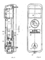
- Fig. 1 die Innenansicht eines Deckels eines Gerätekastens nach der Erfindung in natürlichem Maßstab, gesehen in Pfeilrichtung 1 der Fig. 2;
- Fig. 2 einen Vertikalschnitt durch einen Gerätekasten nach der Erfindung;
- Fig. 3 eine Ausführungsvariante der Erfindung im Vertikalschnitt und einem gegenüber den Fig. 1 und 2 verkleinerten Maßstab;
- Fig. 4 eine Aufsicht auf einen Gerätekasten nach Fig. 3.
- Figure 1 shows the inside view of a cover of a device box according to the invention on a natural scale, seen in the direction of arrow 1 of Fig. 2.
- Figure 2 is a vertical section through an equipment box according to the invention.
- 3 shows an embodiment variant of the invention in vertical section and on a smaller scale compared to FIGS. 1 and 2;
- 4 is a plan view of an equipment box according to FIG. 3.
In den Fig. 1 und 2 ist 1 ein am Ampelmast mit Schrauben 2 in bekannter Weise befestigtes Unterteil und 3 der oben mit einer Nase 4 in einer Öffnung des Unterteils eingehängte und von unten durch Schrauben 5 befestigte Deckel, der demnach durch eine Schwenkbewegung A-B um eine durch die Nase 4 gehende Achse vom Unterteil 1 abgehoben bzw. auf dieses aufgesetzt werden kann.1 and 2, 1 is a lower part fastened to the traffic light mast with screws 2 in a known manner, and 3 is the top which is suspended at the top with a nose 4 in an opening of the lower part and fastened from below by
Das Unterteil 1 nimmt in einer in die Öffnung 6 eingepaßten Muffe mit Zugentlastung nur das Ende des Stromzuführungskabels sowie den Summer 7 auf, dessen Schallöffnungen 8 an der Unterteil-Rückseite 9 austreten, die dadurch keinen Anlaß mehr geben, mit einem geeigneten Werkzeug in das Gehäuseinnere beschädigend oder zerstörend eindringen zu können. Zwar müssen die direkt an der Rückseite und damit am Mast austretenden Schallöffnungen 8 dort in sich über die Breite des Gehäuses erstreckende, rechtwinklige oder schräge Abzweigungen 8′ einmünden, damit der Schall nach außen dringen kann, aber durch die so geschaffenen rechtwinklig abzweigenden Schallwege können keine Werkzeuge bis in das Innere des Gehäuses geführt werden.The lower part 1 receives in a fitting in the opening 6 with strain relief only the end of the power supply cable and the
Im Gehäusedeckel sind außer dem Summer (oder Lautsprecher) und einem Teil der nachfolgend beschriebenen Stromverbindung alle für die gewünschten Schaltungen und Anzeigen erforderlichen Elemente und Geräte, z.B. der Transformator 10, der Gleichrichter 11, die Zeitkonstant-Kondensatoren 12, der Glättungskondensator 13, Widerstände 14, für die Baugruppe "Summer" der Präzisionstimer 15, der Signalgenerator 16 und der Kopplungskondensator 17, ferner Potentiometer 18, Sicherheitsrelais 19, der Varistor 20, ein Vibrator, eine Mikrosicherung 21 und ein sog. Blinden die Richtung des Überweges anzeigendes "Überwegsymbol" 22 untergebracht.In addition to the buzzer (or loudspeaker) and part of the power connection described below, the housing cover contains all the elements and devices required for the desired circuits and displays, e.g. the
Allgemein mit 23 ist die Stromverbindung zwischen dem bei 6 durch die Gehäuserückwand eingeleiteten Zuführungskabel und den im Deckel untergebrachten Elementen und Geräten bezeichnet. Hierz wird das Ende des eingeführten Kabels aufgezweigt und jeder Abzweig mit einer in der Vorderansicht rechteckigen Steckbuchse 25 verbunden, die eine rechteckige mit der Stromzuführung leitend verbundene Öffnung 26 aufweist. Die Zahl der nebeneinanderliegenden Buchsen 25 richtet sich nach der Zahl der erforderlichen Anschlüsse. beim dargestellten Beispiel sind 6 Buchsen angenommen.The electrical connection between the supply cable introduced through the rear wall of the housing at 6 and the elements and devices accommodated in the cover is generally designated by 23. Here, the end of the inserted cable is branched off and each branch is connected to a
Entsprechend den Buchsen 25 sind im Deckel auf einem Sockel 27 nebeneinander elektrisch leitende an die einzelnen Elemente und Geräte angeschlossene Stifte 28 montiert, die beim Aufbringen des Deckels 1 auf das Unterteil 3 in die Öffnungen 26 stromverbindend eintauchen und beim Abnehmen des Deckels sich aus diesen herausziehen und d.h., beim Aufbringen des Dekkels eine Stromverbindung zwischen dem Zuführungskabel und den einzelnen Elementen und Geräten automatisch herstellen und beim Abnehmen des Deckels automatisch unterbrechen. Entsprechend dem von den Stiften 28 beim Zuklappen oder Aufklappen des Deckels an dieser Stelle beschriebenen Schwenkradius ist die Höhe der Öffnungen 26 gewählt, d.h. diese müssen höher sein als die Stifte dick sind, um zu berücksichtigen, daß die Stiftenden beim Auf- und Zuklappen des Deckels einen Kreisbogen beschreiben. Eine andere Möglichkeit wäre, die Öffnungen kleiner zu machen und dafür die Stifte entsprechend dem Schwenkradius zu krümmen.Corresponding to the
Mit 29 ist allgemein der Vibrator bezeichnet, dessen vibrierender Stempfe 30 mit einem Fortsatz 31 und Richtungspfeil 32 unten aus dem Gerätekastengehäuse herausreicht und vom Blinden während der Grünphase als vibrierend erfühlbar ist.The vibrator is generally designated by 29, the vibrating stopper 30 of which extends with an
Der Vibrator, der nur ein feines Vibrieren und kein starkes Schwingen oder gar Rumpeln erzeugen soll, ist erfahrungsgemäß häufig schwierig darauf einzustellen. Deshalb sieht die Erfindung einen in der Höhe verstellbaren, das elektromagnetische Feld und damit die Schwingungsstärke beeinflussenden U-förmigen Bügel 33 vor, der beim dargestellten Beispiel durch zwei Schrauben 34 in Langlöchern 35 des Bügels in der Höhe verstellbar ist.Experience has shown that the vibrator, which is only supposed to produce a fine vibration and not a strong swing or even rumble, is often difficult to adjust to it. The invention therefore provides for a
Der vorbeschriebene und in den Fig. 1 und 2 dargestellte Gerätekasten kann, ohne dadurch breiter zu werden, durch weitere Schaltmöglichkeiten ausgebaut werden, z.B. zu einem Kasten für eine sog. "Anforderungs- oder Bedarfsampel", die beispielsweise einen von außen zu bedienenden Sensor oder einen Druckknopf, ein Hinweisschild "Bitte berühren" und gegebenenfalls auch eine nach dem Einschalten aufleuchtende LED- oder LCD-Anzeige "Signal kommt" vorsieht.The equipment box described above and shown in FIGS. 1 and 2 can be expanded by further switching options without becoming wider as a result become, for example, a box for a so-called "requirement or requirement light", for example a sensor to be operated from the outside or a push button, a sign saying "Please touch" and possibly also an LED or LCD display that lights up after switching on " Signal comes "provides.
Hierzu kann der Kasten in seiner Gestaltung und Bestückung etwa bis zur strichpunktiert eingezeichneten Linie T so bleiben, wie er in den Fig. 1 und 2 dargestellt ist und die Elemente und Geräte, die zusätzlich benötigt werden, in einem aufsetzbaren Teil untergebracht werden. Das heißt, es kann eine Spritzform für das Unterteil hergestellt werden, die bei allen Ausführungen die gleiche ist und die Spritzform für das Oberteil kann je nach Art kurz oder länger daraufgesetzt werden.For this purpose, the design and equipment of the box can remain approximately up to the dash-dotted line T as shown in FIGS. 1 and 2 and the elements and devices which are additionally required can be accommodated in an attachable part. This means that an injection mold for the lower part can be produced, which is the same in all versions, and the injection mold for the upper part can be placed on it shortly or longer, depending on the type.
Als Beispiel ist ein Gerätekasten für eine Bedarfsampel in den Fig. 3 und 4 veranschaulicht, dessen Unterteil UT dem Kasten nach den Fig. 1 und 2 entspricht und dessen Oberteil OT zusätzlich einen Sensor 37 für die bedarfsweise Einschaltung und eine LED- oder LCD-Anzeige 38 "Signal kommt" zusätzlich aufnimmt. Die Aussparung für das Hinweisschild 39 "Bitte berühren" kann durch einfaches Einlegen eines Streifens in die Form erzeugt werden.3 and 4, the lower part of which corresponds to the box according to FIGS. 1 and 2 and the upper part of which also has a
- 1 Unterteil1 lower part
- 2 Schrauben2 screws
- 3 Deckel3 lids
- 4 Nase4 nose
- 5 Schrauben5 screws
- 6 Öffnung6 opening
- 7 Summer7 buzzer
- 8 Schallöffnungen8 sound openings
- 9 Unterteilrückseite9 lower part back
- 10 Transformator10 transformer
- 11 Gleichrichter11 rectifiers
- 12 Zeitkonstant-Kondensatoren12 constant-time capacitors
- 13 Glättungskondensator13 smoothing capacitor
- 14 Widerstände14 resistors
- 15 Präzisionstimer15 precision timers
- 16 Signalgenerator16 signal generator
- 17 Kopplungskondensator17 coupling capacitor
- 18 Potentiometer18 potentiometers
- 19 Sicherheitsrelais19 safety relays
- 20 Varistor20 varistor
- 21 Mikrosicherung21 micro fuse
- 22 Überwegsymbol22 crossing symbol
- 23 Stromverbindung (allgemein)23 power connection (general)
- 2424th
- 25 Steckbuchse25 socket
- 26 Öffnung26 opening
- 27 Sockel27 base
- 28 Stifte28 pens
- 29 Vibrator (allgemein)29 vibrator (general)
- 30 Stempel30 stamps
- 31 Fortsatz31 extension
- 32 Richtungspfeil32 directional arrow
- 33 Bügel33 stirrups
- 34 Schrauben34 screws
- 35 Langlöcher35 slots
- 3636
- 37 Sensor37 sensor
- 38 LED- oder LCD-Anzeige38 LED or LCD display
- 39 Streifen39 strips
Claims (6)
Applications Claiming Priority (2)
| Application Number | Priority Date | Filing Date | Title |
|---|---|---|---|
| DE19893927636 DE3927636C1 (en) | 1989-08-22 | 1989-08-22 | |
| DE3927636 | 1989-08-22 |
Publications (2)
| Publication Number | Publication Date |
|---|---|
| EP0414063A2 true EP0414063A2 (en) | 1991-02-27 |
| EP0414063A3 EP0414063A3 (en) | 1992-12-02 |
Family
ID=6387584
Family Applications (1)
| Application Number | Title | Priority Date | Filing Date |
|---|---|---|---|
| EP19900115361 Withdrawn EP0414063A3 (en) | 1989-08-22 | 1990-08-10 | Apparatus casings for alternating signalling devices |
Country Status (2)
| Country | Link |
|---|---|
| EP (1) | EP0414063A3 (en) |
| DE (1) | DE3927636C1 (en) |
Cited By (1)
| Publication number | Priority date | Publication date | Assignee | Title |
|---|---|---|---|---|
| EP2131341A1 (en) * | 2008-06-05 | 2009-12-09 | LIC Langmatz GmbH | Request device for a traffic light |
Families Citing this family (1)
| Publication number | Priority date | Publication date | Assignee | Title |
|---|---|---|---|---|
| DE102009030159B4 (en) * | 2009-06-24 | 2012-04-19 | Langmatz Gmbh | Request device for a traffic light |
Citations (6)
| Publication number | Priority date | Publication date | Assignee | Title |
|---|---|---|---|---|
| US2461448A (en) * | 1947-04-02 | 1949-02-08 | Smith Everett Manley | Street crossing signal device for blind pedestrians |
| US3624269A (en) * | 1970-03-09 | 1971-11-30 | Veped Traffic Controls Inc | Column for supporting electrical devices embodying a handhole electrical terminal compartment near its base |
| US3999160A (en) * | 1975-12-05 | 1976-12-21 | Mcdonnell Richard M | Modular traffic signal apparatus |
| DE2816683A1 (en) * | 1978-04-18 | 1979-10-31 | Wolfgang Ipach | Acoustic traffic crossing aid for blind persons - has traffic light condition signalled by buzzer generating two separate sounds |
| DE3523526A1 (en) * | 1984-07-30 | 1986-02-06 | Celaya Emparanza y Galdos, S.A., Vitoria | Battery for a portable traffic-signal transmitter |
| US4654745A (en) * | 1984-12-24 | 1987-03-31 | Corby Industries, Inc. | Electronic access control system for use with conventional switch plates and boxes |
Family Cites Families (1)
| Publication number | Priority date | Publication date | Assignee | Title |
|---|---|---|---|---|
| DE1994310U (en) * | 1968-06-28 | 1968-09-19 | Aga Ab | ACOUSTIC SIGNAL DEVICE. |
-
1989
- 1989-08-22 DE DE19893927636 patent/DE3927636C1/de not_active Expired - Fee Related
-
1990
- 1990-08-10 EP EP19900115361 patent/EP0414063A3/en not_active Withdrawn
Patent Citations (6)
| Publication number | Priority date | Publication date | Assignee | Title |
|---|---|---|---|---|
| US2461448A (en) * | 1947-04-02 | 1949-02-08 | Smith Everett Manley | Street crossing signal device for blind pedestrians |
| US3624269A (en) * | 1970-03-09 | 1971-11-30 | Veped Traffic Controls Inc | Column for supporting electrical devices embodying a handhole electrical terminal compartment near its base |
| US3999160A (en) * | 1975-12-05 | 1976-12-21 | Mcdonnell Richard M | Modular traffic signal apparatus |
| DE2816683A1 (en) * | 1978-04-18 | 1979-10-31 | Wolfgang Ipach | Acoustic traffic crossing aid for blind persons - has traffic light condition signalled by buzzer generating two separate sounds |
| DE3523526A1 (en) * | 1984-07-30 | 1986-02-06 | Celaya Emparanza y Galdos, S.A., Vitoria | Battery for a portable traffic-signal transmitter |
| US4654745A (en) * | 1984-12-24 | 1987-03-31 | Corby Industries, Inc. | Electronic access control system for use with conventional switch plates and boxes |
Cited By (1)
| Publication number | Priority date | Publication date | Assignee | Title |
|---|---|---|---|---|
| EP2131341A1 (en) * | 2008-06-05 | 2009-12-09 | LIC Langmatz GmbH | Request device for a traffic light |
Also Published As
| Publication number | Publication date |
|---|---|
| DE3927636C1 (en) | 1990-11-29 |
| EP0414063A3 (en) | 1992-12-02 |
Similar Documents
| Publication | Publication Date | Title |
|---|---|---|
| EP2911141A1 (en) | Lamp | |
| EP0414063A2 (en) | Apparatus casings for alternating signalling devices | |
| DE202021102115U1 (en) | Exercise system for learning electrical circuit arrangements | |
| DE2211061C3 (en) | Electrical installation for rooms with prefabricated walls | |
| DE60009344T2 (en) | ELECTROMAGNETIC RELAY | |
| EP0377866A2 (en) | Travel continuation indicator for a lift system | |
| DE2638613C3 (en) | Device for visual display | |
| DE2147068B2 (en) | Logical electronic circuit element for reader - has four NOR gates with electrical circuit wires to connect to end tags in wafer assembly | |
| DE3713031A1 (en) | Water monitor | |
| LU500067B1 (en) | Exercise system for learning electrical circuit arrangements | |
| DE19963118C1 (en) | Universal coupling device for energy supply chain has selectively removable support lugs for adapting to different coupling points | |
| DE19854584B4 (en) | Electrical installation equipment, in particular earthed socket outlets | |
| DE2841302C2 (en) | Multiple terminal block for electrical lines | |
| DE102009030159B4 (en) | Request device for a traffic light | |
| EP0448508A1 (en) | Punching device | |
| DE2714450A1 (en) | Light signal generator for automatic fire alarms - is made in two half sections held together by protective cap for signal lamp | |
| EP0910234A2 (en) | Function module with indicator for automation apparatus | |
| DE9108297U1 (en) | Adapter panel for electrical installation equipment | |
| DE202022106080U1 (en) | Optical signaling device and networked system comprising such optical signaling device | |
| DE29712392U1 (en) | Electromagnetic switching device with bus-compatible amplifier module | |
| DE2805232A1 (en) | Ventilation control and drive unit - is mounted with microswitches on conductive support plate secured in housing | |
| CH713345A1 (en) | Front terminal. | |
| DE3609720C2 (en) | ||
| DE69604864T2 (en) | Electrical device for assemblable structure attached to the wall, with transparent housing on the back | |
| EP0509116A1 (en) | Pendant switch for controlling lifting devices and for crane-devices |
Legal Events
| Date | Code | Title | Description |
|---|---|---|---|
| PUAI | Public reference made under article 153(3) epc to a published international application that has entered the european phase |
Free format text: ORIGINAL CODE: 0009012 |
|
| AK | Designated contracting states |
Kind code of ref document: A2 Designated state(s): AT BE CH ES FR IT LI LU NL |
|
| PUAL | Search report despatched |
Free format text: ORIGINAL CODE: 0009013 |
|
| AK | Designated contracting states |
Kind code of ref document: A3 Designated state(s): AT BE CH ES FR IT LI LU NL |
|
| STAA | Information on the status of an ep patent application or granted ep patent |
Free format text: STATUS: THE APPLICATION IS DEEMED TO BE WITHDRAWN |
|
| 18D | Application deemed to be withdrawn |
Effective date: 19930301 |