EP0413630B1 - Verfahren und Vorrichtung zum Hochdruckwasserstrahlschneiden dicker Bahnen aus weichem Material - Google Patents
Verfahren und Vorrichtung zum Hochdruckwasserstrahlschneiden dicker Bahnen aus weichem Material Download PDFInfo
- Publication number
- EP0413630B1 EP0413630B1 EP90402288A EP90402288A EP0413630B1 EP 0413630 B1 EP0413630 B1 EP 0413630B1 EP 90402288 A EP90402288 A EP 90402288A EP 90402288 A EP90402288 A EP 90402288A EP 0413630 B1 EP0413630 B1 EP 0413630B1
- Authority
- EP
- European Patent Office
- Prior art keywords
- blade
- nozzle
- fact
- axis
- jet
- Prior art date
- Legal status (The legal status is an assumption and is not a legal conclusion. Google has not performed a legal analysis and makes no representation as to the accuracy of the status listed.)
- Expired - Lifetime
Links
- 238000005520 cutting process Methods 0.000 title claims description 39
- XLYOFNOQVPJJNP-UHFFFAOYSA-N water Substances O XLYOFNOQVPJJNP-UHFFFAOYSA-N 0.000 title claims description 17
- 238000000034 method Methods 0.000 title claims description 8
- 239000007779 soft material Substances 0.000 title 1
- 239000000463 material Substances 0.000 claims description 7
- 230000000295 complement effect Effects 0.000 claims description 2
- 239000012530 fluid Substances 0.000 claims description 2
- 238000002955 isolation Methods 0.000 claims description 2
- 230000008961 swelling Effects 0.000 claims 1
- 239000002131 composite material Substances 0.000 description 3
- 239000000919 ceramic Substances 0.000 description 2
- 239000006185 dispersion Substances 0.000 description 2
- 235000013372 meat Nutrition 0.000 description 2
- OKTJSMMVPCPJKN-UHFFFAOYSA-N Carbon Chemical compound [C] OKTJSMMVPCPJKN-UHFFFAOYSA-N 0.000 description 1
- 229920000049 Carbon (fiber) Polymers 0.000 description 1
- 229920000271 Kevlar® Polymers 0.000 description 1
- 241001465754 Metazoa Species 0.000 description 1
- 230000001154 acute effect Effects 0.000 description 1
- 229910052799 carbon Inorganic materials 0.000 description 1
- 239000004917 carbon fiber Substances 0.000 description 1
- 238000006243 chemical reaction Methods 0.000 description 1
- 230000006835 compression Effects 0.000 description 1
- 238000007906 compression Methods 0.000 description 1
- 239000000470 constituent Substances 0.000 description 1
- 235000014510 cooky Nutrition 0.000 description 1
- 230000003247 decreasing effect Effects 0.000 description 1
- 229910003460 diamond Inorganic materials 0.000 description 1
- 239000010432 diamond Substances 0.000 description 1
- 230000000694 effects Effects 0.000 description 1
- 239000004744 fabric Substances 0.000 description 1
- 239000002657 fibrous material Substances 0.000 description 1
- 238000010438 heat treatment Methods 0.000 description 1
- 239000004761 kevlar Substances 0.000 description 1
- 238000004519 manufacturing process Methods 0.000 description 1
- 230000003647 oxidation Effects 0.000 description 1
- 238000007254 oxidation reaction Methods 0.000 description 1
- 229920000642 polymer Polymers 0.000 description 1
- 239000011150 reinforced concrete Substances 0.000 description 1
- HBMJWWWQQXIZIP-UHFFFAOYSA-N silicon carbide Chemical compound [Si+]#[C-] HBMJWWWQQXIZIP-UHFFFAOYSA-N 0.000 description 1
- 229910010271 silicon carbide Inorganic materials 0.000 description 1
- 239000007787 solid Substances 0.000 description 1
- 238000003892 spreading Methods 0.000 description 1
- 238000002604 ultrasonography Methods 0.000 description 1
- 238000011144 upstream manufacturing Methods 0.000 description 1
Images
Classifications
-
- B—PERFORMING OPERATIONS; TRANSPORTING
- B26—HAND CUTTING TOOLS; CUTTING; SEVERING
- B26F—PERFORATING; PUNCHING; CUTTING-OUT; STAMPING-OUT; SEVERING BY MEANS OTHER THAN CUTTING
- B26F3/00—Severing by means other than cutting; Apparatus therefor
- B26F3/004—Severing by means other than cutting; Apparatus therefor by means of a fluid jet
-
- Y—GENERAL TAGGING OF NEW TECHNOLOGICAL DEVELOPMENTS; GENERAL TAGGING OF CROSS-SECTIONAL TECHNOLOGIES SPANNING OVER SEVERAL SECTIONS OF THE IPC; TECHNICAL SUBJECTS COVERED BY FORMER USPC CROSS-REFERENCE ART COLLECTIONS [XRACs] AND DIGESTS
- Y10—TECHNICAL SUBJECTS COVERED BY FORMER USPC
- Y10T—TECHNICAL SUBJECTS COVERED BY FORMER US CLASSIFICATION
- Y10T83/00—Cutting
- Y10T83/02—Other than completely through work thickness
-
- Y—GENERAL TAGGING OF NEW TECHNOLOGICAL DEVELOPMENTS; GENERAL TAGGING OF CROSS-SECTIONAL TECHNOLOGIES SPANNING OVER SEVERAL SECTIONS OF THE IPC; TECHNICAL SUBJECTS COVERED BY FORMER USPC CROSS-REFERENCE ART COLLECTIONS [XRACs] AND DIGESTS
- Y10—TECHNICAL SUBJECTS COVERED BY FORMER USPC
- Y10T—TECHNICAL SUBJECTS COVERED BY FORMER US CLASSIFICATION
- Y10T83/00—Cutting
- Y10T83/04—Processes
- Y10T83/0448—With subsequent handling [i.e., of product]
- Y10T83/0467—By separating products from each other
-
- Y—GENERAL TAGGING OF NEW TECHNOLOGICAL DEVELOPMENTS; GENERAL TAGGING OF CROSS-SECTIONAL TECHNOLOGIES SPANNING OVER SEVERAL SECTIONS OF THE IPC; TECHNICAL SUBJECTS COVERED BY FORMER USPC CROSS-REFERENCE ART COLLECTIONS [XRACs] AND DIGESTS
- Y10—TECHNICAL SUBJECTS COVERED BY FORMER USPC
- Y10T—TECHNICAL SUBJECTS COVERED BY FORMER US CLASSIFICATION
- Y10T83/00—Cutting
- Y10T83/04—Processes
- Y10T83/0591—Cutting by direct application of fluent pressure to work
-
- Y—GENERAL TAGGING OF NEW TECHNOLOGICAL DEVELOPMENTS; GENERAL TAGGING OF CROSS-SECTIONAL TECHNOLOGIES SPANNING OVER SEVERAL SECTIONS OF THE IPC; TECHNICAL SUBJECTS COVERED BY FORMER USPC CROSS-REFERENCE ART COLLECTIONS [XRACs] AND DIGESTS
- Y10—TECHNICAL SUBJECTS COVERED BY FORMER USPC
- Y10T—TECHNICAL SUBJECTS COVERED BY FORMER US CLASSIFICATION
- Y10T83/00—Cutting
- Y10T83/202—With product handling means
- Y10T83/2074—Including means to divert one portion of product from another
- Y10T83/2077—By kerf entering guide
-
- Y—GENERAL TAGGING OF NEW TECHNOLOGICAL DEVELOPMENTS; GENERAL TAGGING OF CROSS-SECTIONAL TECHNOLOGIES SPANNING OVER SEVERAL SECTIONS OF THE IPC; TECHNICAL SUBJECTS COVERED BY FORMER USPC CROSS-REFERENCE ART COLLECTIONS [XRACs] AND DIGESTS
- Y10—TECHNICAL SUBJECTS COVERED BY FORMER USPC
- Y10T—TECHNICAL SUBJECTS COVERED BY FORMER US CLASSIFICATION
- Y10T83/00—Cutting
- Y10T83/364—By fluid blast and/or suction
Definitions
- the invention firstly relates to a process for cutting thick sheets of flexible material, offering for example a fibrous texture, using a device emitting a jet of water at high pressure.
- the laser causes significant heating with the risk of oxidation of the material constituting the sheet which is to be cut; the conventional jet of water loses its effectiveness; as for cutting with a cookie cutter, it has the drawback of deforming by crushing the sheet by the effect of compression which precedes the actual cutting process and of requiring regular sharpening of the tooling.
- the object of the invention is to allow the cutting, using a high pressure water jet, of sheets of flexible material, in particular fibrous material, and of medium or heavy thickness.
- the method makes it possible to cut sheets of fibrous texture whose thickness can reach 50 cm and more in certain cases.
- the invention also relates to a device for cutting with a pressurized jet for thick plies of flexible texture, comprising a base carrying a profiled blade which extends along a longitudinal axis and which, starting from a thick longitudinal zone adjacent to said axis, tapering laterally from at least one side of this axis to an acute edge parallel or substantially parallel to said axis, this blade being provided with a nozzle which, supplied with pressurized fluid, emits in the plane by means of the blade a jet cutting the sheet,
- a device of this kind is described in document US-A-4 226 005.
- This device intended for cutting carcasses of meat animals, comprises a blade provided with several nozzles, which are in fact nozzles emitting compressed air jets, which cut the meat to a soft consistency.
- Such a device would be ineffective for cutting plies of flexible material, but relatively firm and elastic, such as the fibrous plies used in the field of composite materials.
- the blade of the device according to the present invention comprises a single nozzle mounted at the end of the profiled blade which is located opposite the base; this nozzle, supplied with pressurized water, emits a fine and ultra-fast water jet cutting along an emission axis coinciding with the longitudinal axis of the blade, while the longitudinal zone of the latter offers, in the nozzle region, a thickness decreasing to said end.
- the profiled blade with which the device according to the invention is provided oriented so that its mean plane is parallel to the direction of the relative movement of the device and of the sheet to be cut, enters the slot formed during the preceding pass or passes cutting and spreads the walls in the vicinity of the jet, preserving it from any untimely contact likely to affect its effectiveness.
- the blade also has the function of spreading the cut sides to provide the passage of the nozzle between these sides, the spacing being however as small as possible to limit the friction due to the reaction of the texture of the sheet which tends to become close.
- the edge or each aforementioned edge curves in approaching the axis of the nozzle, so that said end is shaped peak. This arrangement facilitates the introduction of the blade into the cutting slot.
- the blade can be produced according to two conformations. In one it is entirely located on the same side of said axis and has only one edge. In the other, it has two edges and tapers on either side of said thick zone towards each of these. This configuration allows an alternating movement of the cutting device relative to the web, while the first is reserved for the case where the direction of relative movement of the device is invariable.
- the blade can be made either in one piece, or by assembling two complementary pieces respectively disposed on either side of the axis of the nozzle.
- the nozzle can be mounted either in the region of the end of the blade close to the base, the blade, preferably removably mounted on the base to which the nozzle is then fixed, comprising a longitudinal channel surrounding the axis of the nozzle at a distance and giving free passage to the jet along the length of the blade, that is to say in the region of the thinned end of the blade, opposite the base, a conduit for supplying the nozzle with water under pressure being provided inside the blade.
- provision may be made, if necessary, for said thinned end of the blade to follow a bulge dimensioned so as to accommodate the nozzle when the latter is larger than the thickness of the blade.
- the blade may have, at its thinned end remote from the base, a jet release notch.
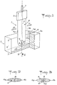
- Figure 1 shows in perspective a cutting device according to the invention equipped with a double-edged blade.
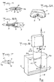
- FIG. 2 represents a cross section of the blade of the device of FIG. 1.
- FIG. 3 represents a view along arrow III of the blade of the device of FIG. 1.
- FIG. 4 represents a cross section of an alternative embodiment of the blade of the device of FIG. 1.
- Figures 5A and 5B show, respectively in perspective and in longitudinal section, the end of the blade of the device of Figure 1 arranged to receive a relatively large nozzle.
- Figure 6 shows, like Figure 1, a device according to the invention in an alternative embodiment.
- FIG. 7 represents a view along arrow VII of the blade of the device of FIG. 6.
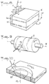
- Figures 8 to 10 show in perspective, in a simplified manner, three examples of the use of a device according to the invention.
- FIG. 1 shows a device 1 for cutting under a pressurized water jet used to cut into two blocks 2a, 2b a thick sheet 2 of fibrous texture.
- the device 1 comprises a base 3 for fixing to a mechanism capable of animating it with a translational movement relative to the fibrous sheet 2 in a direction D or D ′, a blade 4 attached to the base 3 or, as in the present example, made in one piece with it, and a nozzle 5 incorporated in the blade 4, not far from its end opposite to the base 3, and capable of emitting by a narrow nozzle 5a (FIG. 3) a fine and ultra-fast cutting jet of water 6 when it is supplied with pressurized water via a connection pipe 7 and a conduit 8 formed through the base 3 and the blade 4.
- a narrow nozzle 5a FIG. 3
- the latter present in for the most part a flattened cylindrical conformation of section in the shape of a shuttle (FIGS. 2 and 3) whose longitudinal axis 9 coincides with the cutting jet 6.
- the blade 4 thus has a relatively thick middle part between two parts going in slimming to end with sharp edges 4a, 4b situ in the middle plane of the blade. This extends somewhat beyond the nozzle 5 by an end in the form of a thinned point where the two edges 4a, 4b curve to approach the axis 9, while a notch 10 is formed therein to allow jet 6 to develop freely at the outlet of nozzle 5.
- the device shown is designed to cut a thick fibrous sheet 2, the thickness E of which is greater than the thickness H that the jet 6 can cut in one pass, the value of this thickness H depending on the cutting performance of the jet 6 for the particular texture of the sheet 2.
- the cutting of the latter is therefore carried out in several successive passes made by translational movement of the device 1 alternately in the direction of arrow D, then in the opposite direction (arrow D ').
- the device After each cutting pass, the device, the blade 4 of which is oriented so that its mean plane is parallel to the direction of movement D or D ', is lowered by a new quantity H, the blade 4 sinking, with the nozzle 5, in the slot 12 previously cut in the sheet 2.
- the sides 12a, 12b of this slot which would naturally tend to close against one another by seriously disturbing the jet 6, are thus kept apart by blade 4 in the region of the latter.
- the blade 4 is a single piece in which the conduit 8 has been drilled for supplying the nozzle 5.
- the blade 4 can be produced in two symmetrical parts 4 ′, 4 '' ( Figure 4), each comprising one of the two edges 4a, 4b, which are assembled along a joint plane 14 passing through the axis 9 of the nozzle.
- a tube 18 housed in a longitudinal recess hollowed out in one and the other parts 4 ', 4' 'constituting the blade 4.
- These parts can be made of sintered ceramic or ceramic composite.
- the end of the blade 4 can be given a shape showing a bulge 11 of thickness e 'slightly greater than said diameter, which constitutes a fairing capable of housing the nozzle 5, fixed for example by screwing. It should in practice that the thickness e of the blade 4 is at most equal to 3 mm, and that the thickness e 'of the bulge 11 does not exceed 6 mm.
- FIG. 6 shows a cutting device no longer equipped with a double-edged blade 4, but with a blade 4 ′ reduced to one of the two constituent parts of a conforming blade in FIG. 4.
- This blade 4 ' entirely situated on the same side of the cutting jet 6, is suitable when the direction of movement of the device relative to the ply 2, indicated by the arrow D, is always the same, l 'edge 4a being constantly upstream of the cutting jet 6.
- the blade 4' is removable.
- the nozzle 5 of the device of Figure 6 is placed not in the vicinity of the end of the blade opposite to the base 3, but in a location close to the latter. More specifically, the nozzle 5 is fixed on the base 3, taking place in a notch 13 formed at the end of the blade 4 'by which it is itself fixed to the base 3.
- the nozzle 5 does not not penetrate the sheet 2, and the jet 6 that it emits must travel the entire length of the blade 4 '; it performs this route in a channel 15 in the form of a gutter, hollowed out in the blade 4 ', which protects it from any coming into contact with the sides 12a, 12b of the cutting slot 12 in which the blade 4' plunges.
- a notch 10 is provided at the end of the blade through which the jet 6 emerges.
- the device of FIG. 6 is used by making a first cutting pass, the blade 4 'having been removed; then, after having reassembled on the base 3 the blade, its end plunging into the cut made during this first pass, a second pass is made without lowering the device, so as to cut the sheet to an additional thickness.
- the arrangement of the nozzle 5 in the vicinity of the base 3 has the advantage of accommodating a nozzle of the current commercial model. However, it requires the addition of a polymer in the water supplying the nozzle in order to avoid dispersion of the jet. In addition, it leads to lower cutting performance in depth than that of the first version ( Figure 1).
- FIG. 8 illustrates the cutting of a wafer 2a in a fixed ply 2 of significant thickness E using a device 1 with reciprocating movement, equipped with a blade 4 with double edge 4a, 4b.
- FIG. 9 illustrates the cutting of washers in a thick cylindrical sheet 2 animated by a rotational movement, around its axis 16, the device 1 remaining fixed.
- a simplified blade device according to Figure 6 can be used.
- a battery of several devices 1 (for example a dozen) can be provided, distributed along the axis 16 of the cylindrical sheet 2, for simultaneously cutting several washers therein.
- FIG. 10 shows how a piece of revolution 22 of axis 17 can be cut from a flat thick sheet 2, driven by a rotational movement, externally limited by a surface in the form of a straight cylinder and internally by a frustoconical surface.
Landscapes
- Life Sciences & Earth Sciences (AREA)
- Forests & Forestry (AREA)
- Engineering & Computer Science (AREA)
- Mechanical Engineering (AREA)
- Perforating, Stamping-Out Or Severing By Means Other Than Cutting (AREA)
- Nonmetal Cutting Devices (AREA)
Claims (13)
- Verfahren zum Schneiden von dicken Schichten anhand einer Vorrichtung zum Abstrahlen eines Hochdruck-Wasserstrahls, wobei das Schneiden in mehreren aufeinanderfolgenden Durchgängen erfolgt, dadurch gekennzeichnet, daß eine Trennung des Strahls gegenüber den Seitenflächen des Spaltes, der bereits in einem Teilabschnitt der Gesamtdicke der aus biegsamem Material bestehenden, beispielsweise eine faserige Struktur aufweisenden Schicht geschnitten wurde, durchgehend dadurch gewährleistet wird, daß die Seitenflächen mit Hilfe der Vorrichtung auseinandergehalten werden.
- Verfahren nach Anspruch 1, dadurch gekennzeichnet, daß nach jedem der aufeinanderfolgenden Durchgänge die Schneidvorrichtung nach und nach in die Dicke der Schicht eingesenkt wird.
- Druckstrahlschneidvorrichtung für dicke Schichten mit biegsamer Struktur mit einem Ansatz, an dem ein Profilmesser (4; 4') angebracht ist, das in einer Längsachse (9) verläuft und das von einer dickeren Längszone in der Nähe dieser Achse (9) aus allmählich in seitlicher Richtung auf mindestens einer Seite dieser Achse zu einer parallel oder in etwa parallel zur Achse (9) angeordneten scharfen Kante (4a, 4b) hin dünner wird, wobei dieses Messer mit einer Düse (5) bestückt ist, die unter Zufuhr einer unter Druck stehenden Flüssigkeit in der Mittelebene des Messers einen Strahl zum Schneiden der Schicht ausstößt, dadurch gekennzeichnet, daß die Düse (5) an dem Ende des Profilmessers (4; 4') angebracht ist, das dem Ansatz (3) gegenüberliegt, daß sie unter Zufuhr von Druckwasser einen dünnen und extrem schnellen Schneidwasserstrahl in einer Strahlachse ausstößt, die mit der Längsachse (9) des Messers (4; 4') zusammenfällt, und daß die Längszone des Messers im Bereich der Düse (5) eine zu dem besagten Ende hin abnehmende Dicke aufweist.
- Vorrichtung nach Anspruch 3, dadurch gekennzeichnet, daß die Kante bzw. jede vorgenannte Kante (4a, 4b) im Bereich des dem Ansatz (3) gegenüberliegenden Endes des Messers (4; 4'), nach innen gekrümmt ist, wobei sie sich der Achse (9) der Düse annähert, so daß dieses Ende spitzenförmig ausgebildet ist.
- Vorrichtung nach Anspruch 3 oder 4, dadurch gekennzeichnet daß das Messer (4') vollständig auf ein und derselben Seite der Achse (9) angeordnet ist und nur eine einzige Kante (4a) aufweist.
- Vorrichtung nach Anspruch 3 oder 4, dadurch gekennzeichnet, daß das Messer (4) zwei Kanten (4a, 4b) aufweist und auf beiden Seiten der dickeren Zone zu jeder dieser Kanten hin dünner wird.
- Vorrichtung nach einem der Ansprüche 3 bis 6, dadurch gekennzeichnet, daß das Messer (4; 4') einstückig ausgeführt ist.
- Vorrichtung nach einem der Ansprüche 3, 4 und 6, dadurch gekennzeichnet, daß das Messer (4) durch die Zusammenfügung von zwei sich ergänzenden Teilen (4', 4'') gebildet wird, die jeweils auf einer Seite der Achse (9) der Düse angeordnet sind.
- Vorrichtung nach einem der Ansprüche 3 bis 8, dadurch gekennzeichnet, daß die Düse (5) in dem Bereich des zum Ansatz (3) hin gelegenen Endes des Messers (4') angebracht ist und daß das Messer einen Längskanal (15) aufweist, der die Achse (9) der Düse mit einem gewissen Abstand umgibt und dem Strahl (6) über die Länge des Messers freien Durchgang verschafft.
- Vorrichtung nach Anspruch 9, dadurch gekennzeichnet, daß die Düse (5) am Ansatz (3) befestigt ist und daß das Messer (4') in abnehmbarer Form an diesem Ansatz angebracht ist.
- Vorrichtung nach einem der Ansprüche 3 bis 8, dadurch gekennzeichnet, daß die Düse (5) im Bereich des dem Ansatz (3) gegenüberliegenden Endes mit abnehmender Dicke des Messers (4) angebracht ist, wobei im Innern des Messers eine Leitung (8) für die Zufuhr von Druckwasser zur Düse vorgesehen ist.
- Vorrichtung nach Anspruch 11, dadurch gekennzeichnet, daß sich das Ende mit abnehmender Dicke des Messers (4) an eine Verdickung (11) anschließt, die so bemessen ist, daß sie die Düse (5) aufnehmen kann.
- Vorrichtung nach einem der Ansprüche 3 bis 12, dadurch gekennzeichnet, daß das Messer (4; 4') an seinem dem Ansatz gegenüberliegenden Ende eine bogenförmige Aussparung (10) für den Austritt des Strahls (6) aufweist.
Applications Claiming Priority (2)
| Application Number | Priority Date | Filing Date | Title |
|---|---|---|---|
| FR8910989A FR2650973B1 (fr) | 1989-08-17 | 1989-08-17 | Procede et dispositif de decoupe au jet d'eau a haute pression de nappes epaisses de matiere souple |
| FR8910989 | 1989-08-17 |
Publications (2)
| Publication Number | Publication Date |
|---|---|
| EP0413630A1 EP0413630A1 (de) | 1991-02-20 |
| EP0413630B1 true EP0413630B1 (de) | 1993-11-18 |
Family
ID=9384775
Family Applications (1)
| Application Number | Title | Priority Date | Filing Date |
|---|---|---|---|
| EP90402288A Expired - Lifetime EP0413630B1 (de) | 1989-08-17 | 1990-08-13 | Verfahren und Vorrichtung zum Hochdruckwasserstrahlschneiden dicker Bahnen aus weichem Material |
Country Status (5)
| Country | Link |
|---|---|
| US (1) | US5097731A (de) |
| EP (1) | EP0413630B1 (de) |
| CA (1) | CA2023413C (de) |
| DE (1) | DE69004635T2 (de) |
| FR (1) | FR2650973B1 (de) |
Families Citing this family (12)
| Publication number | Priority date | Publication date | Assignee | Title |
|---|---|---|---|---|
| US5236459A (en) * | 1989-09-06 | 1993-08-17 | Sulzer Brothers Limited | Bone implant and method of making same |
| US5599223A (en) * | 1991-04-10 | 1997-02-04 | Mains Jr.; Gilbert L. | Method for material removal |
| GB2259875B (en) * | 1991-09-28 | 1994-08-17 | Luk Lamellen & Kupplungsbau | Process for manufacturing a brake band |
| US5322504A (en) * | 1992-05-07 | 1994-06-21 | United States Surgical Corporation | Method and apparatus for tissue excision and removal by fluid jet |
| US5620414A (en) * | 1992-06-30 | 1997-04-15 | Campbell, Jr.; Robert M. | Apparatus and method for effecting surgical incision through use of a fluid jet |
| US6305261B1 (en) * | 1998-03-23 | 2001-10-23 | Alan J. Romanini | Hand-held tool for cutting with high pressure water |
| US6217670B1 (en) | 1998-12-31 | 2001-04-17 | Cf Gomma Usa, Inc. | Method of manufacturing coated fluid tubing |
| AT407873B (de) * | 1999-12-13 | 2001-07-25 | Lisec Peter | Verfahren und vorrichtung zum durchtrennen von folien in verbundglas |
| US6616372B2 (en) * | 2000-07-21 | 2003-09-09 | John M. Seroka | Process for making products using waterjet technology and computer software |
| GB0807964D0 (en) | 2008-05-02 | 2008-06-11 | Rolls Royce Plc | A method of fluid jet machining |
| FR2956057B1 (fr) * | 2010-02-10 | 2012-01-27 | Snecma | Decoupe de preformes avant injection rtm par jet d'eau et cryogenisation |
| EP2617540B1 (de) * | 2012-01-20 | 2014-03-19 | Alstom Technology Ltd | Prallplatte zum Steuern von Hochdruck-Flüssigkeitsstrahlen |
Family Cites Families (13)
| Publication number | Priority date | Publication date | Assignee | Title |
|---|---|---|---|---|
| FR1443632A (fr) * | 1965-07-30 | 1966-06-24 | British Nylon Spinners Ltd | Procédé perfectionné de coupe de fils, d'étoffes et d'autres matières textiles |
| DE2749830C2 (de) * | 1977-11-08 | 1985-10-24 | Gewerkschaft Eisenhütte Westfalia, 4670 Lünen | Hobelmeißel |
| US4265487A (en) * | 1978-04-10 | 1981-05-05 | The Curators Of The University Of Missouri | High pressure water jet mining machine |
| US4226005A (en) * | 1979-04-20 | 1980-10-07 | Meyers William G | Apparatus and tool for cutting animal carcasses by impinging air jets |
| GB2027776A (en) * | 1979-08-09 | 1980-02-27 | Gutehoffnungshuette Sterkrade | Cutting a Solid Body |
| US4532949A (en) * | 1982-09-29 | 1985-08-06 | The Boeing Company | Energy absorber for high energy fluid jet |
| DE3563768D1 (en) * | 1984-05-04 | 1988-08-18 | Minnovation Ltd | Mineral cutting device, water supply lance and cutter pick |
| US4669229A (en) * | 1985-07-10 | 1987-06-02 | Flow Systems, Inc. | Energy dissipating receptacle for high-velocity fluid jet |
| GB2180142A (en) * | 1985-09-14 | 1987-03-25 | Tsann Dao Wang | Removing flesh from coconuts |
| US4733914A (en) * | 1985-09-19 | 1988-03-29 | Gerb. Eickhoff Maschinenfabrik Und Eisengiesserei | Apparatus to deliver high pressure liquid from nozzles on a shearer drum for a mining machine |
| KR930008692B1 (ko) * | 1986-02-20 | 1993-09-13 | 가와사끼 쥬고교 가부시기가이샤 | 어브레시브 워터 제트 절단방법 및 장치 |
| DE3836074A1 (de) * | 1987-10-26 | 1989-05-03 | De Beers Ind Diamond | Schneidmeissel |
| US4934111A (en) * | 1989-02-09 | 1990-06-19 | Flow Research, Inc. | Apparatus for piercing brittle materials with high velocity abrasive-laden waterjets |
-
1989
- 1989-08-17 FR FR8910989A patent/FR2650973B1/fr not_active Expired - Fee Related
-
1990
- 1990-08-13 DE DE69004635T patent/DE69004635T2/de not_active Expired - Fee Related
- 1990-08-13 EP EP90402288A patent/EP0413630B1/de not_active Expired - Lifetime
- 1990-08-16 US US07/568,417 patent/US5097731A/en not_active Expired - Lifetime
- 1990-08-16 CA CA002023413A patent/CA2023413C/fr not_active Expired - Fee Related
Also Published As
| Publication number | Publication date |
|---|---|
| FR2650973A1 (fr) | 1991-02-22 |
| CA2023413C (fr) | 2000-01-11 |
| EP0413630A1 (de) | 1991-02-20 |
| DE69004635T2 (de) | 1994-06-09 |
| US5097731A (en) | 1992-03-24 |
| CA2023413A1 (fr) | 1991-02-18 |
| FR2650973B1 (fr) | 1991-12-06 |
| DE69004635D1 (de) | 1993-12-23 |
Similar Documents
| Publication | Publication Date | Title |
|---|---|---|
| EP0413630B1 (de) | Verfahren und Vorrichtung zum Hochdruckwasserstrahlschneiden dicker Bahnen aus weichem Material | |
| EP1778456B1 (de) | Verfahren und vorrichtung zur ultraschallverarbeitung einer materialbahn | |
| CA2488835A1 (fr) | Fil de coupe ameliore pour un appareil de coupe de vegetaux | |
| EP1872901A1 (de) | Drehendes Bearbeitungswerkzeug, insbesondere zum Schneiden, mit einer Vorrichtung zur Entfernung der Bearbeitungsspäne | |
| EP0375526A1 (de) | Präzisions-Hohlbohr-Werkzeug für Verbundwerkstoff-Paneele | |
| WO1999019598A1 (fr) | Accouplement pour dispositif a transmission de forces | |
| WO2007134989A1 (fr) | Dispositif et methode de percage de produits en caoutchouc | |
| WO2010081939A1 (fr) | Dispositif de projection de jets d'eau par une plaquette perforée courbee | |
| EP0077226B1 (de) | Handwerkzeug für die Materialabhebung an einem Werkstück, insbesondere für die Entgratung und die Kantenbrechung | |
| EP0730498B1 (de) | Düse zur oberflächenbehandlung sowie vorrichtung und verfahren zur oberflächenbehandlung mit einer solchen düse | |
| EP0175612A1 (de) | Bearbeitungsvorrichtung mit einem das Werkzeug umgebenden Niederhalter, und Niederhalter dafür | |
| EP1777201A1 (de) | Verfahren und Vorrichtung zur Behandlung einer mit einem schützenden Film beschichteten Glasscheibe | |
| EP0086368B1 (de) | Schneidwerkzeug | |
| FR2483844A1 (fr) | Emporte-piece rotatif | |
| FR2503048A1 (fr) | Nouveau dispositif de coupe adaptable aux installations d'ouverture et de tri du courrier | |
| FR2737078A1 (fr) | Elagueur portatif hydraulique | |
| EP0005657B1 (de) | Vorrichtung zur Herstellung von Spänen aus kleinen Platten | |
| EP0997242B1 (de) | Verfahren sowie Vorrichtung zum Schneiden von Rohren | |
| EP2000270B1 (de) | Rückholvorrichtung für Schneidedorn eines Spiralschneiders | |
| FR2868725A1 (fr) | Procede de fabrication d'une lame tranchante | |
| EP1792658B1 (de) | Messervorrichtung für Lebensmittelzerkleinerungsmaschine, insbesondere für Fleischwölfe | |
| FR2659250A1 (fr) | Couteau pour equiper une tete de coupe d'une granulatrice et granulatrice. | |
| EP0274373B1 (de) | Reinigungsvorrichtung für ein Förderband | |
| CH347603A (fr) | Procédé de fabrication d'articles adhésifs destinés à des usages médicaux et chirurgicaux, appareil pour la mise en oeuvre de ce procédé, et article obtenu par ce procédé | |
| BE1015094A3 (fr) | Element de coupe et outil d'usinage pourvu d'un tel element. |
Legal Events
| Date | Code | Title | Description |
|---|---|---|---|
| PUAI | Public reference made under article 153(3) epc to a published international application that has entered the european phase |
Free format text: ORIGINAL CODE: 0009012 |
|
| AK | Designated contracting states |
Kind code of ref document: A1 Designated state(s): DE GB IT |
|
| 17P | Request for examination filed |
Effective date: 19901221 |
|
| 17Q | First examination report despatched |
Effective date: 19920128 |
|
| GRAA | (expected) grant |
Free format text: ORIGINAL CODE: 0009210 |
|
| AK | Designated contracting states |
Kind code of ref document: B1 Designated state(s): DE GB IT |
|
| REF | Corresponds to: |
Ref document number: 69004635 Country of ref document: DE Date of ref document: 19931223 |
|
| ITF | It: translation for a ep patent filed | ||
| GBT | Gb: translation of ep patent filed (gb section 77(6)(a)/1977) |
Effective date: 19940209 |
|
| PLBE | No opposition filed within time limit |
Free format text: ORIGINAL CODE: 0009261 |
|
| STAA | Information on the status of an ep patent application or granted ep patent |
Free format text: STATUS: NO OPPOSITION FILED WITHIN TIME LIMIT |
|
| 26N | No opposition filed | ||
| REG | Reference to a national code |
Ref country code: GB Ref legal event code: 732E |
|
| REG | Reference to a national code |
Ref country code: GB Ref legal event code: IF02 |
|
| PGFP | Annual fee paid to national office [announced via postgrant information from national office to epo] |
Ref country code: GB Payment date: 20030805 Year of fee payment: 14 |
|
| PGFP | Annual fee paid to national office [announced via postgrant information from national office to epo] |
Ref country code: DE Payment date: 20030807 Year of fee payment: 14 |
|
| PG25 | Lapsed in a contracting state [announced via postgrant information from national office to epo] |
Ref country code: GB Free format text: LAPSE BECAUSE OF NON-PAYMENT OF DUE FEES Effective date: 20040813 |
|
| PG25 | Lapsed in a contracting state [announced via postgrant information from national office to epo] |
Ref country code: DE Free format text: LAPSE BECAUSE OF NON-PAYMENT OF DUE FEES Effective date: 20050301 |
|
| GBPC | Gb: european patent ceased through non-payment of renewal fee |
Effective date: 20040813 |
|
| PG25 | Lapsed in a contracting state [announced via postgrant information from national office to epo] |
Ref country code: IT Free format text: LAPSE BECAUSE OF NON-PAYMENT OF DUE FEES;WARNING: LAPSES OF ITALIAN PATENTS WITH EFFECTIVE DATE BEFORE 2007 MAY HAVE OCCURRED AT ANY TIME BEFORE 2007. THE CORRECT EFFECTIVE DATE MAY BE DIFFERENT FROM THE ONE RECORDED. Effective date: 20050813 |