EP0413570A2 - Picture data compression - Google Patents
Picture data compression Download PDFInfo
- Publication number
- EP0413570A2 EP0413570A2 EP19900308957 EP90308957A EP0413570A2 EP 0413570 A2 EP0413570 A2 EP 0413570A2 EP 19900308957 EP19900308957 EP 19900308957 EP 90308957 A EP90308957 A EP 90308957A EP 0413570 A2 EP0413570 A2 EP 0413570A2
- Authority
- EP
- European Patent Office
- Prior art keywords
- data
- component data
- encoding
- pass filter
- compressed
- Prior art date
- Legal status (The legal status is an assumption and is not a legal conclusion. Google has not performed a legal analysis and makes no representation as to the accuracy of the status listed.)
- Withdrawn
Links
Images


Classifications
-
- H—ELECTRICITY
- H04—ELECTRIC COMMUNICATION TECHNIQUE
- H04N—PICTORIAL COMMUNICATION, e.g. TELEVISION
- H04N19/00—Methods or arrangements for coding, decoding, compressing or decompressing digital video signals
- H04N19/60—Methods or arrangements for coding, decoding, compressing or decompressing digital video signals using transform coding
- H04N19/63—Methods or arrangements for coding, decoding, compressing or decompressing digital video signals using transform coding using sub-band based transform, e.g. wavelets
-
- H—ELECTRICITY
- H04—ELECTRIC COMMUNICATION TECHNIQUE
- H04N—PICTORIAL COMMUNICATION, e.g. TELEVISION
- H04N19/00—Methods or arrangements for coding, decoding, compressing or decompressing digital video signals
- H04N19/10—Methods or arrangements for coding, decoding, compressing or decompressing digital video signals using adaptive coding
- H04N19/102—Methods or arrangements for coding, decoding, compressing or decompressing digital video signals using adaptive coding characterised by the element, parameter or selection affected or controlled by the adaptive coding
- H04N19/124—Quantisation
-
- H—ELECTRICITY
- H04—ELECTRIC COMMUNICATION TECHNIQUE
- H04N—PICTORIAL COMMUNICATION, e.g. TELEVISION
- H04N19/00—Methods or arrangements for coding, decoding, compressing or decompressing digital video signals
- H04N19/60—Methods or arrangements for coding, decoding, compressing or decompressing digital video signals using transform coding
-
- H—ELECTRICITY
- H04—ELECTRIC COMMUNICATION TECHNIQUE
- H04N—PICTORIAL COMMUNICATION, e.g. TELEVISION
- H04N19/00—Methods or arrangements for coding, decoding, compressing or decompressing digital video signals
- H04N19/90—Methods or arrangements for coding, decoding, compressing or decompressing digital video signals using coding techniques not provided for in groups H04N19/10-H04N19/85, e.g. fractals
- H04N19/98—Adaptive-dynamic-range coding [ADRC]
Definitions
- This invention relates to a highly efficient coding apparatus for picture data for compressing the amount of data for a digital picture signal.
- Sub-band coding has been proposed as a technique for compressing the amount of transmission data necessary to transmit a picture signal, and involves splitting an input signal into plural frequency bands and encoding the signal of each band; this can reduce the disturbing effect of quantisation noise and decrease the number of bits which the transmitted data contains.
- FIG. 1 of the accompanying drawings shows a conventional encoding apparatus.
- a digital picture signal from an input terminal indicated at 1 is supplied to a filter bank 2 and divided into plural frequency bands.
- the filter bank 2 is a two-dimensional filter and can divide respective bands in the horizontal direction and the vertical direction.
- the first output signal of the filter bank 2 is provided through a low-pass filter (called "LL components") with respect to both frequency components of the horizontal and vertical frequencies.
- the second output signal of the filter bank 2 are the "LH" components which are provided through a low-pass filter with respect to the horizontal frequency and a high-pass filter with respect to the vertical frequency.
- the third output signal is HL components
- the fourth output signal is components.
- the LL components which contain much information are supplied to a transformation circuit 51 for DCT (Discrete cosine transform) so that the amount of the information is compressed by the DCT.
- the transformation circuit 51 includes a block segmentation circuit for converting input data into a block structure of (8 x 8), for example, and by the conversion and encoding of the output signal of the block segmentation circuit, an 8 x 8 matrix of coefficient data is generated from the transformation circuit 51.
- the coefficient data generated from the transformation circuit 51 is subjected to linear or non-linear step quantisation at a quantisation circuit 53.
- the output signal of the quantisation circuit 52 is supplied to an encoder 52 which produces variable length codes in a form such as Hufman code.
- LH components, HL components, HH components other than the LL components are supplied to variable-length encoders 7, 8 and 9 using codes such as Hufman code through quantisation circuits 4, 5 and 6, respectively. Compression of data is carried out by the quantisation circuits 52, 4, 5 and 6 and the encoders 53, 7, 8 and 9. The output signals of the encoders 53, 7, 8 and 9 are converted by a frame segmentation circuit 10 into transmission data and taken out at an output terminal 11.
- Figure 2 shows the structure on the reception side corresponding to the transmission side of figure 1.
- Reception data from an input terminal indicated at 21 is given to a frame separation circuit 22 and divided into the signal of each band.
- the LL components are supplied to an inverse transformer 54 for cosine conversion, and the decoding of the DCT is carried out. Also, the order of the data is converted into the original one at a block separation circuit.
- the output signal of the inverse transformer 54 is supplied to a decoder 55 for variable length codes.
- the components other than the LL components are supplied to decoders 24, 25 and 26 for variable length codes, respectively.
- the output signals of the decoders 55, 24, 25 and 26 are fed to a filter bank 27 and combined into a signal of one band in terms of frequencies. Reproduced picture data is provided at an output terminal 28 of the filter bank 27.
- An object of the invention is, therefore, to provide a highly efficient coding apparatus in which is the above stated disadvantages inherent in the conventional encoding apparatus by the compression and encoding of low frequency component signals in the level direction are reduced or eliminated.
- a highly efficient coding apparatus for coding digital picture data to provide compressed picture data, comprising: filter bank means arranged to be supplied with said digital picture data and for splitting the same into a plurality of component data in different frequency bands; a plurality of encoding means each of which is arranged to be supplied with respective component data from the filter bank means and for encoding the component data to generate compressed component data; and combining means for combining the compressed component data from said plurality of encoding means to provide said compressed picture data, wherein at least one of said plurality of encoding means for encoding the component data having the lowest frequency band incudes block segmentation means for forming blocks of component data representing plural picture elements, first and second detecting means for detecting maximum and minimum values, respectively, of the component data representing the plural picture elements in each of said blocks, means for generating dynamic range information for each said block from said maximum and minimum values for the respective block, means for generating modified component data for each said block as the difference between each of the digital picture data and one of said maximum
- Fig. 3 shows a structure on the transmission side of one embodiment.
- a digital video signal in which one picture element data is quantized into 8 bits, for example, is supplied to an input terminal indicated at 1.
- the digital video signal is given to a filter bank 2 encircled by a broken line and divided into data of four bands in the two-dimensional frequency region.
- the filter bank 2 is made up of digital filters 12 and 13 to which an input signal is given, digital filters 14 and 15 to which the output signal of the digital filter 12 is supplied, and digital filters 16and 17 to which the output signal of the digital filter 13 is fed.
- the digital filter 12 is a low-pass filter in the horizontal direction
- the digital filter 13 is a high-pass filter in the horizontal direction.
- the digital filters 14 and 16 are low-pass filters in the vertical direction
- the digital filters 15 and 17 are high-pass filters in the vertical direction.
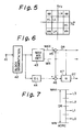
- the output signal of th digital filter 14 is a low frequency signal LL indicated by a rectangular area with the origin as its center in Fig. 5 which illustrates a two-dimensional frequency characteristic of a horizontal frequency Fh and a vertical frequency Fv, since the output signal is passed through the low-pass filters in both of the horizontal and vertical direction.
- the output signal of the digital filter 15 is a signal LH passed through the low-pass filter in the horizontal direction and through the high-pass filter in the vertical direction.
- the output signal of the digital filter 16 is a signal HL passed through the high-pass filter in the horizontal direction and through the low-pass filter in the vertical direction.
- the output signal of the digital filter 17 is a signal HH passed through the high-pass filter in the horizontal direction and through the high-pass filter in the vertical direction.
- an original signal has a band of 1/2 Fs (Fs: sampling frequency in the horizontal direction and vertical direction.
- Each digital filter of the filter bank 2 has a structure for lowering the sampling frequency to 1/4 of that of th original signal.
- a resampling circuit for altering th sampling frequency to 1/4 may be provided on the output side of the filter bank 2. In this way, with the sampling frequency decreased, the data amount is kept unchanged.
- the lowest frequency signal LL among the output signals of the filter bank 2 is supplied to an ADRC encoder 3.
- the ADRC encoder 3 performs compression and encoding in the level direction of time region, and one example of its structure is shown in Fig. 6.
- the output signal of the digital filter 14 is supplied to an input terminal indicated at 41.
- the input signal is converted into the order of a two-dimensional block from that of the television scanning by a block segmentation circuit 42.
- the two-dimensional block has the size of (4 ⁇ 4), (8 ⁇ 8), etc.
- the output signal of the block segmentation circuit 42 is supplied to a maximum value, minimum value detecting circuit 43 and a delay circuit 44.
- the maximum value MAX and the minimum value MIN of picture data are detected for every block by the detecting circuit 43.
- the maximum value MAX and the minimum value MIN are supplied to a subtracter 45, and a dynamic range DR, which is a difference between both values, is calculated at the subtracter 45.
- the picture data through the delay circuit 44 is given to a subtracter 46, and data which is provided by subtracting the minimum value MIN from the picture data is obtained from the subtracter 46.
- the subtraction of the minimum value MIN is to normalize picture data in a block, and the picture data may be subtracted from the maximum value MAX.
- the output signal of the subtracter 46 is supplied to the quantization circuit 47.
- the dynamic range DR is supplied to the quantization circuit 47.
- post-minimum-value-elimination data is requantized with a bit number less than the original bit number.
- Fig. 7 is for explaining the quantization in the case of the bit number of two bits, for example.
- the dynamic range DR is divided into four, and the quantization step size is obtained.
- Picture data from the subtracter 46 is divided by the quantization step size, and its quotient is made to an integer by the omitting process to provide a two-bit code signal DT (00) (10) (01) or (11).
- the quantization circuit 47 is composed of a dividing circuit or an ROM.
- representative values L0, L1, L2 and L3 indicate reproduction levels on the decoding side.
- the dynamic range DR, the minimum value MIN and the code signal DT are transmitted.
- two pieces of information may be sent among the dynamic range DR, the maximum value MAX and the minimum value MIN.
- the ADRC compresses the data amount to be sent using the facts that a partial picture of block size has correlation in the level direction and that generating distortion can be decreased even if the quantization is done with the bit number less than the original bit number.
- the output signal (code signal DT, dynamic range DR and the minimum value MIN) from the ADRC encoder 3 is given to a frame segmentation circuit 10 as shown in Fig. 3.
- Signal components of other bands of the filter bank 2 are supplied to quantization circuits 4, 5 and 6, respectively.
- the quantization circuits 4, 5 and 6 perform requantization of input data with a bit number less than the original one. Namely, the quantization circuits 4, 5 and 6 perform step quantization. The width of a dead zone where the step size and quantization output become zero is set at an optimal one.
- the output signals of the respective quantization circuits 4, 5 and 6 are given to variable length code encoders 7, 8 and 9 for Hafman code, etc. Compression of a data amount is performed with the processing of the quantization circuits 4, 5 and 6 and the encoders 7, 8 and 9.
- the output signals of these encoders 7, 8 and 9 are supplied to the frame segmentation circuit 10.
- the frame segmentation circuit 10 converts an encoded signal of each band into transmission data of one channel. Transmission data taken out to an output terminal 11 of the frame segmentation circuit 10 is transmitted or recorded.
- Fig. 4 shows a structure on the reception side which makes a pair with the structure on the transmission side shown in Fig. 3.
- Reception data is given to a frame separation circuit 22 from an input terminal 21 and desegmented into an encoded signal of each band.
- the encoded signals of other bands are supplied to variable length code decoders 24, 25 and 26, respectively.
- An ADRC decoder 23 is a circuit for obtaining a post-minimum-value-elimination value on the basis of a dynamic range DR and a code signal DT by an ROM, a multiplier, etc. and adding to this value the minimum value MIN to generate a reproduction level.
- a block separation circuit is provided at the ADRC decoder 23 to convert data arranged in the order of blocks into the original order.
- the output signal of the ADRC decoder 23 and the respective output signals of the decoders 24, 25 and 26 are supplied to a filter bank 27 encircled by a broken line.
- the output signal of the ADRC decoder 23 is supplied to an adder 33 through a digital filter 29 which is a low-pass filter in the vertical direction.
- the output signal of the decoder 24 is given to the adder 33 through a digital filter 30 which is a high- pass filter in the vertical direction.
- the output signal of the decoder 25 is fed to an adder 34 through a digital filter 31 which is a low-pass filter in the vertical direction.
- the output signal of the decoder 26 is given to the adder 34 through a digital filter 32 which is a high-pass filter in the vertical direction.
- the output signal of the adder 33 is supplied to an adder 36 through a digital filter 35 which is a low-pass filter in the horizontal direction, and the output signal of the adder 34 is fed to an adder 36 through a digital filter 37 which is a high-pass filter in the horizontal direction.
- the output signal of the adder 36 is taken out at an output terminal 28.
- Each digital filter of the filter bank 27 functions to carry out an interpolation and convert a sampling frequency into that of the original signal.
- An interpolating circuit may be provided separately on the output side of the filter bank 27.
- the filter bank 2 on the transmission side and the filter bank 27 on the reception side have a relationship where they can be reconstructed.
- the same output signals for the input signals to the filter bank 2 can be provided from the filter bank 27.
- signals of other bands as well as signal components of the lowest band may be encoded at the ADRC.
- the ADRC may perform quantization at a variable length (for example, a bit number of 0, 1, 2, 3 or 4 bits) depending on a three-dimensional block ADRC and a dynamic range DR.
- this invention compresses low frequency components having the greatest information amount in the level direction by ADRC, the degradation of definition is less, the hardware size is small, and an error of a code signal is not propagated in a block as compared with a conventional system using cosine conversion.
Landscapes
- Engineering & Computer Science (AREA)
- Multimedia (AREA)
- Signal Processing (AREA)
- Compression Or Coding Systems Of Tv Signals (AREA)
- Color Television Systems (AREA)
- Compression, Expansion, Code Conversion, And Decoders (AREA)
Abstract
Description
- This invention relates to a highly efficient coding apparatus for picture data for compressing the amount of data for a digital picture signal.
- Sub-band coding has been proposed as a technique for compressing the amount of transmission data necessary to transmit a picture signal, and involves splitting an input signal into plural frequency bands and encoding the signal of each band; this can reduce the disturbing effect of quantisation noise and decrease the number of bits which the transmitted data contains.
- Figure 1 of the accompanying drawings shows a conventional encoding apparatus. A digital picture signal from an input terminal indicated at 1 is supplied to a
filter bank 2 and divided into plural frequency bands. Thefilter bank 2 is a two-dimensional filter and can divide respective bands in the horizontal direction and the vertical direction. The first output signal of thefilter bank 2 is provided through a low-pass filter (called "LL components") with respect to both frequency components of the horizontal and vertical frequencies. The second output signal of thefilter bank 2 are the "LH" components which are provided through a low-pass filter with respect to the horizontal frequency and a high-pass filter with respect to the vertical frequency. The third output signal is HL components, and the fourth output signal is components. - The LL components which contain much information are supplied to a
transformation circuit 51 for DCT (Discrete cosine transform) so that the amount of the information is compressed by the DCT. Thetransformation circuit 51 includes a block segmentation circuit for converting input data into a block structure of (8 x 8), for example, and by the conversion and encoding of the output signal of the block segmentation circuit, an 8 x 8 matrix of coefficient data is generated from thetransformation circuit 51. The coefficient data generated from thetransformation circuit 51 is subjected to linear or non-linear step quantisation at a quantisation circuit 53. The output signal of the quantisation circuit 52 is supplied to an encoder 52 which produces variable length codes in a form such as Hufman code. - Other LH components, HL components, HH components other than the LL components are supplied to variable-
length encoders 7, 8 and 9 using codes such as Hufman code throughquantisation circuits quantisation circuits encoders 53, 7, 8 and 9. The output signals of theencoders 53, 7, 8 and 9 are converted by aframe segmentation circuit 10 into transmission data and taken out at anoutput terminal 11. - Figure 2 shows the structure on the reception side corresponding to the transmission side of figure 1. Reception data from an input terminal indicated at 21 is given to a
frame separation circuit 22 and divided into the signal of each band. The LL components are supplied to aninverse transformer 54 for cosine conversion, and the decoding of the DCT is carried out. Also, the order of the data is converted into the original one at a block separation circuit. The output signal of theinverse transformer 54 is supplied to a decoder 55 for variable length codes. - The components other than the LL components are supplied to
decoders decoders filter bank 27 and combined into a signal of one band in terms of frequencies. Reproduced picture data is provided at anoutput terminal 28 of thefilter bank 27. - Since the above mentioned conventional highly efficient coding apparatus for picture data performs step quantisation of coefficient data provided through the DCT, so that the high frequency side of the LL components is discarded, there is the disadvantage that the definition of the reproduced picture is degraded. Moreover, the hardware of transformer DCT requires a lot of calculation circuits of 14- to 16-bit word length when the quantisation bit number of picture data is 8 bits. Therefore, there is a problem that the hardware size becomes large. Further, when data becomes erroneous due to an error generated in a transmission system, there is the problem that entire blocks are affected by the error since coefficient data of the DCT belongs to the frequency region.
- An object of the invention is, therefore, to provide a highly efficient coding apparatus in which is the above stated disadvantages inherent in the conventional encoding apparatus by the compression and encoding of low frequency component signals in the level direction are reduced or eliminated.
- According to an aspect of the invention there is provided a highly efficient coding apparatus for coding digital picture data to provide compressed picture data, comprising:
filter bank means arranged to be supplied with said digital picture data and for splitting the same into a plurality of component data in different frequency bands;
a plurality of encoding means each of which is arranged to be supplied with respective component data from the filter bank means and for encoding the component data to generate compressed component data; and
combining means for combining the compressed component data from said plurality of encoding means to provide said compressed picture data,
wherein at least one of said plurality of encoding means for encoding the component data having the lowest frequency band incudes block segmentation means for forming blocks of component data representing plural picture elements, first and second detecting means for detecting maximum and minimum values, respectively, of the component data representing the plural picture elements in each of said blocks, means for generating dynamic range information for each said block from said maximum and minimum values for the respective block, means for generating modified component data for each said block as the difference between each of the digital picture data and one of said maximum and minimum values for said respective block, means for encoding said modified component data with a digitised bit number less than the number of bits in said component data so as to provide the compressed component data, and output means for outputting the compressed data and an additional code for each said respective block formed of at least two of said maximum and minimum values and a signal corresponding to said dynamic range information. - The invention will be further described by way of non-limitative example with reference to the accompanying drawings, in which:-
- Figures 1 and 2 are block diagrams showing respective structures on the transmission and reception sides of one embodiment of the invention;
- Figure 3 is a block diagram of a structure on the transmission side of one embodiment of the invention;
- Figure 4 is a block diagram of a structure on the reception side of one embodiment of the invention;
- Figure 5 is a schematic diagram for explaining a filter bank characteristic;
- Figure 6 is a block diagram of one example of an ADRC encoder; and
- Figure 7 is a schematic diagram for describing the operation of the ADRC encoder.
- An embodiment of this invention will be described with reference to the drawings hereunder. Fig. 3 shows a structure on the transmission side of one embodiment. In Fig. 3, a digital video signal in which one picture element data is quantized into 8 bits, for example, is supplied to an input terminal indicated at 1. The digital video signal is given to a
filter bank 2 encircled by a broken line and divided into data of four bands in the two-dimensional frequency region. - The
filter bank 2 is made up ofdigital filters digital filters digital filter 12 is supplied, anddigital filters 16and 17 to which the output signal of thedigital filter 13 is fed. Thedigital filter 12 is a low-pass filter in the horizontal direction, and thedigital filter 13 is a high-pass filter in the horizontal direction. Thedigital filters digital filters - The output signal of th
digital filter 14 is a low frequency signal LL indicated by a rectangular area with the origin as its center in Fig. 5 which illustrates a two-dimensional frequency characteristic of a horizontal frequency Fh and a vertical frequency Fv, since the output signal is passed through the low-pass filters in both of the horizontal and vertical direction. The output signal of thedigital filter 15 is a signal LH passed through the low-pass filter in the horizontal direction and through the high-pass filter in the vertical direction. The output signal of thedigital filter 16 is a signal HL passed through the high-pass filter in the horizontal direction and through the low-pass filter in the vertical direction. The output signal of thedigital filter 17 is a signal HH passed through the high-pass filter in the horizontal direction and through the high-pass filter in the vertical direction. - Here, an original signal has a band of 1/2 Fs (Fs: sampling frequency in the horizontal direction and vertical direction.
- Each digital filter of the
filter bank 2 has a structure for lowering the sampling frequency to 1/4 of that of th original signal. A resampling circuit for altering th sampling frequency to 1/4 may be provided on the output side of thefilter bank 2. In this way, with the sampling frequency decreased, the data amount is kept unchanged. - The lowest frequency signal LL among the output signals of the
filter bank 2 is supplied to an ADRCencoder 3. The ADRCencoder 3 performs compression and encoding in the level direction of time region, and one example of its structure is shown in Fig. 6. In Fig. 6, the output signal of thedigital filter 14 is supplied to an input terminal indicated at 41. The input signal is converted into the order of a two-dimensional block from that of the television scanning by ablock segmentation circuit 42. The two-dimensional block has the size of (4 × 4), (8 × 8), etc. - The output signal of the
block segmentation circuit 42 is supplied to a maximum value, minimumvalue detecting circuit 43 and adelay circuit 44. The maximum value MAX and the minimum value MIN of picture data are detected for every block by the detectingcircuit 43. The maximum value MAX and the minimum value MIN are supplied to asubtracter 45, and a dynamic range DR, which is a difference between both values, is calculated at thesubtracter 45. - The picture data through the
delay circuit 44 is given to asubtracter 46, and data which is provided by subtracting the minimum value MIN from the picture data is obtained from thesubtracter 46. The subtraction of the minimum value MIN is to normalize picture data in a block, and the picture data may be subtracted from the maximum value MAX. The output signal of thesubtracter 46 is supplied to thequantization circuit 47. The dynamic range DR is supplied to thequantization circuit 47. In thequantization circuit 47, post-minimum-value-elimination data is requantized with a bit number less than the original bit number. - Fig. 7 is for explaining the quantization in the case of the bit number of two bits, for example. The dynamic range DR is divided into four, and the quantization step size is obtained. Picture data from the
subtracter 46 is divided by the quantization step size, and its quotient is made to an integer by the omitting process to provide a two-bit code signal DT (00) (10) (01) or (11). Thequantization circuit 47 is composed of a dividing circuit or an ROM. In Fig. 7, representative values L0, L1, L2 and L3 indicate reproduction levels on the decoding side. - The dynamic range DR, the minimum value MIN and the code signal DT are transmitted. For the transmission of the dynamic range information, two pieces of information may be sent among the dynamic range DR, the maximum value MAX and the minimum value MIN. The ADRC compresses the data amount to be sent using the facts that a partial picture of block size has correlation in the level direction and that generating distortion can be decreased even if the quantization is done with the bit number less than the original bit number.
- The output signal (code signal DT, dynamic range DR and the minimum value MIN) from the
ADRC encoder 3 is given to aframe segmentation circuit 10 as shown in Fig. 3. - Signal components of other bands of the
filter bank 2 are supplied toquantization circuits quantization circuits quantization circuits respective quantization circuits length code encoders 7, 8 and 9 for Hafman code, etc. Compression of a data amount is performed with the processing of thequantization circuits encoders 7, 8 and 9. The output signals of theseencoders 7, 8 and 9 are supplied to theframe segmentation circuit 10. Theframe segmentation circuit 10 converts an encoded signal of each band into transmission data of one channel. Transmission data taken out to anoutput terminal 11 of theframe segmentation circuit 10 is transmitted or recorded. - Fig. 4 shows a structure on the reception side which makes a pair with the structure on the transmission side shown in Fig. 3. Reception data is given to a
frame separation circuit 22 from aninput terminal 21 and desegmented into an encoded signal of each band. The encoded signals of other bands are supplied to variablelength code decoders - An
ADRC decoder 23 is a circuit for obtaining a post-minimum-value-elimination value on the basis of a dynamic range DR and a code signal DT by an ROM, a multiplier, etc. and adding to this value the minimum value MIN to generate a reproduction level. A block separation circuit is provided at theADRC decoder 23 to convert data arranged in the order of blocks into the original order. The output signal of theADRC decoder 23 and the respective output signals of thedecoders filter bank 27 encircled by a broken line. - The output signal of the
ADRC decoder 23 is supplied to anadder 33 through adigital filter 29 which is a low-pass filter in the vertical direction. The output signal of thedecoder 24 is given to theadder 33 through adigital filter 30 which is a high- pass filter in the vertical direction. The output signal of thedecoder 25 is fed to anadder 34 through adigital filter 31 which is a low-pass filter in the vertical direction. The output signal of thedecoder 26 is given to theadder 34 through adigital filter 32 which is a high-pass filter in the vertical direction. The output signal of theadder 33 is supplied to anadder 36 through adigital filter 35 which is a low-pass filter in the horizontal direction, and the output signal of theadder 34 is fed to anadder 36 through adigital filter 37 which is a high-pass filter in the horizontal direction. The output signal of theadder 36 is taken out at anoutput terminal 28. - Each digital filter of the
filter bank 27 functions to carry out an interpolation and convert a sampling frequency into that of the original signal. An interpolating circuit may be provided separately on the output side of thefilter bank 27. Further, thefilter bank 2 on the transmission side and thefilter bank 27 on the reception side have a relationship where they can be reconstructed. Clearly, when four output signals of thefilter bank 2 are directly supplied to four input terminals of thefilter bank 27, the same output signals for the input signals to thefilter bank 2 can be provided from thefilter bank 27. - Here, signals of other bands as well as signal components of the lowest band may be encoded at the ADRC. Also, the ADRC may perform quantization at a variable length (for example, a bit number of 0, 1, 2, 3 or 4 bits) depending on a three-dimensional block ADRC and a dynamic range DR.
- Since this invention compresses low frequency components having the greatest information amount in the level direction by ADRC, the degradation of definition is less, the hardware size is small, and an error of a code signal is not propagated in a block as compared with a conventional system using cosine conversion.
- Having described a specific preferred embodiment of the present invention with reference to the accompanying drawings, it is to be understood that the invention is not limited to that precise embodiment, and that various changes and modifications may be effected therein by one skilled in the art without departing from the scope of the invention as defined in the appended claims.
Claims (6)
filter bank means arranged to be supplied with said digital picture data and for splitting the same into a plurality of component data in different frequency bands;
a plurality of encoding means each of which is arranged to be supplied with respective component data from the filter bank means and for encoding the component data to generate compressed component data; and
combining means for combining the compressed component data from said plurality of encoding means to provide said compressed picture data,
wherein at least one of said plurality of encoding means for encoding the component data having the lowest frequency band incudes block segmentation means for forming blocks of component data representing plural picture elements, first and second detecting means for detecting maximum and minimum values, respectively, of the component data representing the plural picture elements in each of said blocks, means for generating dynamic range information for each said block from said maximum and minimum values for the respective block, means for generating modified component data for each said block as the difference between each of the digital picture data and one of said maximum and minimum values for said respective block, means for encoding said modified component data with a digitised bit number less than the number of bits in said component data so as to provide the compressed component data, and output means for outputting the compressed data and an additional code for each said respective block formed of at least two of said maximum and minimum values and-a signal corresponding to said dynamic range information.
Applications Claiming Priority (2)
| Application Number | Priority Date | Filing Date | Title |
|---|---|---|---|
| JP210447/89 | 1989-08-15 | ||
| JP1210447A JPH0374968A (en) | 1989-08-15 | 1989-08-15 | Encoder for picture data |
Publications (2)
| Publication Number | Publication Date |
|---|---|
| EP0413570A2 true EP0413570A2 (en) | 1991-02-20 |
| EP0413570A3 EP0413570A3 (en) | 1992-03-25 |
Family
ID=16589484
Family Applications (1)
| Application Number | Title | Priority Date | Filing Date |
|---|---|---|---|
| EP19900308957 Withdrawn EP0413570A3 (en) | 1989-08-15 | 1990-08-15 | Picture data compression |
Country Status (3)
| Country | Link |
|---|---|
| EP (1) | EP0413570A3 (en) |
| JP (1) | JPH0374968A (en) |
| KR (1) | KR910005690A (en) |
Cited By (8)
| Publication number | Priority date | Publication date | Assignee | Title |
|---|---|---|---|---|
| GB2252021A (en) * | 1991-01-11 | 1992-07-22 | Sony Broadcast & Communication | Data compression |
| EP0497058A2 (en) * | 1990-12-28 | 1992-08-05 | Sony Corporation | Video coding apparatus |
| EP0522219A1 (en) * | 1991-07-11 | 1993-01-13 | International Business Machines Corporation | Improved method for subband coding images and device for implementing said method |
| US5214502A (en) * | 1991-01-11 | 1993-05-25 | Sony Broadcast & Communications Limited | Compression of video signals |
| US5262858A (en) * | 1990-12-05 | 1993-11-16 | Deutsche Itt Industries Gmbh | Method of converting the clock rate of a digitized signal |
| EP0570818A2 (en) * | 1992-05-19 | 1993-11-24 | Sony Corporation | Apparatus for and method of transmitting video signal |
| EP0578355A2 (en) * | 1992-07-06 | 1994-01-12 | Sony United Kingdom Limited | Digital video tape recording/playback system and signal processing apparatus therefor |
| US5757973A (en) * | 1991-01-11 | 1998-05-26 | Sony Corporation | Compression of image data seperated into frequency component data in a two dimensional spatial frequency domain |
Citations (2)
| Publication number | Priority date | Publication date | Assignee | Title |
|---|---|---|---|---|
| EP0217017A2 (en) * | 1985-09-03 | 1987-04-08 | International Business Machines Corporation | Signal coding process and system for implementing said process |
| EP0293189A2 (en) * | 1987-05-29 | 1988-11-30 | Sony Corporation | High efficiency coding apparatus |
-
1989
- 1989-08-15 JP JP1210447A patent/JPH0374968A/en active Pending
-
1990
- 1990-08-14 KR KR1019900012497A patent/KR910005690A/en not_active Application Discontinuation
- 1990-08-15 EP EP19900308957 patent/EP0413570A3/en not_active Withdrawn
Patent Citations (2)
| Publication number | Priority date | Publication date | Assignee | Title |
|---|---|---|---|---|
| EP0217017A2 (en) * | 1985-09-03 | 1987-04-08 | International Business Machines Corporation | Signal coding process and system for implementing said process |
| EP0293189A2 (en) * | 1987-05-29 | 1988-11-30 | Sony Corporation | High efficiency coding apparatus |
Non-Patent Citations (4)
| Title |
|---|
| OPTICAL ENGINEERING, vol. 27, no. 7, July 1988, pages 574-586, Bellingham, WA, US; G. KARLSSON et al.: "Subband coding of video for packet networks" * |
| PROCEEDINGS IEEE, SOUTHEASTCON '89, Columbia, South Carolina, 9th - 12th April 1989, vol. 2, pages 872-876, IEEE, New York, US; R.H. BAMBERGER et al.: "Predictive coding schemes for subband image coders" * |
| PROCEEDINGS OF THE NATIONAL COMMUNICATIONS FORUM, vol. 42, no. 2, 30th September 1988, pages 1682-1685, Chicago, Illinois, US; D. LE GALL et al.: "Transmission of HDTV signals under 140 Mbits/s using a sub-band decomposition and discrete cosine transform coding" * |
| PROCEEDINGS OF THE THIRD INTERNATIONAL WORKSHOP ON HDTV, Turin, 30th August - 1st September 1989, pages 813-820, L. Chiariglione (ed.); T. SOMOGYI et al.: "Coding of progressively scanned HDTV signals at the H4 data rate (140 Mbits/sec) of the digital hierarchy" * |
Cited By (17)
| Publication number | Priority date | Publication date | Assignee | Title |
|---|---|---|---|---|
| US5262858A (en) * | 1990-12-05 | 1993-11-16 | Deutsche Itt Industries Gmbh | Method of converting the clock rate of a digitized signal |
| EP0497058A2 (en) * | 1990-12-28 | 1992-08-05 | Sony Corporation | Video coding apparatus |
| EP0497058A3 (en) * | 1990-12-28 | 1993-02-24 | Sony Corporation | Highly efficient coding apparatus |
| GB2252021B (en) * | 1991-01-11 | 1995-03-08 | Sony Broadcast & Communication | Data compression |
| US5214502A (en) * | 1991-01-11 | 1993-05-25 | Sony Broadcast & Communications Limited | Compression of video signals |
| US5757973A (en) * | 1991-01-11 | 1998-05-26 | Sony Corporation | Compression of image data seperated into frequency component data in a two dimensional spatial frequency domain |
| GB2252021A (en) * | 1991-01-11 | 1992-07-22 | Sony Broadcast & Communication | Data compression |
| EP0522219A1 (en) * | 1991-07-11 | 1993-01-13 | International Business Machines Corporation | Improved method for subband coding images and device for implementing said method |
| US5631978A (en) * | 1991-07-11 | 1997-05-20 | International Business Machines Corporation | Method and apparatus for subband coding images |
| EP0570818A3 (en) * | 1992-05-19 | 1994-08-10 | Sony Corp | Apparatus for and method of transmitting video signal |
| US5420636A (en) * | 1992-05-19 | 1995-05-30 | Sony Corporation | Apparatus for and method of transmitting video signal |
| EP0570818A2 (en) * | 1992-05-19 | 1993-11-24 | Sony Corporation | Apparatus for and method of transmitting video signal |
| EP0578355A3 (en) * | 1992-07-06 | 1994-11-09 | Sony Uk Ltd | Digital video tape recording/playback system and signal processing apparatus therefor. |
| US5506687A (en) * | 1992-07-06 | 1996-04-09 | Sony Corporation | Digital signal recording and/or reproducing apparatus that evenly distributes field data across tracks |
| EP0578355A2 (en) * | 1992-07-06 | 1994-01-12 | Sony United Kingdom Limited | Digital video tape recording/playback system and signal processing apparatus therefor |
| EP0877528A1 (en) * | 1992-07-06 | 1998-11-11 | Sony United Kingdom Limited | Digital signal processing apparatus |
| EP0881831A1 (en) * | 1992-07-06 | 1998-12-02 | Sony United Kingdom Limited | Digital signal processing apparatus |
Also Published As
| Publication number | Publication date |
|---|---|
| JPH0374968A (en) | 1991-03-29 |
| KR910005690A (en) | 1991-03-30 |
| EP0413570A3 (en) | 1992-03-25 |
Similar Documents
| Publication | Publication Date | Title |
|---|---|---|
| US5253075A (en) | Image signal coding/decoding system using adaptive quantization | |
| EP0451545B1 (en) | Apparatus and method for adaptively compressing successive blocks of digital video | |
| EP1701552B1 (en) | Image conversion apparatus | |
| US5434622A (en) | Image signal encoding apparatus using adaptive frame/field format compression | |
| US5361098A (en) | Methods and apparatus for generating a picture-in-picture digital television frame by inserting a mean-only frame into a full-size frame | |
| US5432555A (en) | Image signal encoding apparatus using adaptive 1D/2D DCT compression technique | |
| US5850261A (en) | Efficient variable length encoder and decoder | |
| US5528606A (en) | Error correcting apparatus | |
| EP0413570A2 (en) | Picture data compression | |
| KR100196838B1 (en) | Apparatus for encoding an image signal according to correlation of blocks | |
| KR100359671B1 (en) | Encoder and decoder | |
| JP3020505B2 (en) | Image encoding device, image decoding device, and image transmission device | |
| JP3211989B2 (en) | Orthogonal transform encoding device and decoding device | |
| JPH0549021A (en) | High efficient coder | |
| KR100220583B1 (en) | Image encoder having adaptive encoder | |
| KR940008582B1 (en) | Encoding and decoding circuit | |
| US5917946A (en) | Method and apparatus for encoding an image signal having an object by using the shape thereof | |
| KR100206924B1 (en) | Encoder and decoder in image processing system | |
| JPH0216887A (en) | Picture encodor | |
| JP2846206B2 (en) | Subband coding device | |
| JPS62193382A (en) | System and device for encoding and decoding picture signal | |
| JPH01137785A (en) | High efficient encoding device | |
| Stavroulakis et al. | Applications of statistical signal processing in image data compression | |
| JPH05236451A (en) | Moving image processor | |
| JPH0530536A (en) | Image coding device |
Legal Events
| Date | Code | Title | Description |
|---|---|---|---|
| PUAI | Public reference made under article 153(3) epc to a published international application that has entered the european phase |
Free format text: ORIGINAL CODE: 0009012 |
|
| AK | Designated contracting states |
Kind code of ref document: A2 Designated state(s): DE FR GB |
|
| PUAL | Search report despatched |
Free format text: ORIGINAL CODE: 0009013 |
|
| AK | Designated contracting states |
Kind code of ref document: A3 Designated state(s): DE FR GB |
|
| 17P | Request for examination filed |
Effective date: 19920831 |
|
| 17Q | First examination report despatched |
Effective date: 19941017 |
|
| STAA | Information on the status of an ep patent application or granted ep patent |
Free format text: STATUS: THE APPLICATION IS DEEMED TO BE WITHDRAWN |
|
| 18D | Application deemed to be withdrawn |
Effective date: 19950228 |