EP0413502A1 - Heavy duty pneumatic tires - Google Patents
Heavy duty pneumatic tires Download PDFInfo
- Publication number
- EP0413502A1 EP0413502A1 EP90308723A EP90308723A EP0413502A1 EP 0413502 A1 EP0413502 A1 EP 0413502A1 EP 90308723 A EP90308723 A EP 90308723A EP 90308723 A EP90308723 A EP 90308723A EP 0413502 A1 EP0413502 A1 EP 0413502A1
- Authority
- EP
- European Patent Office
- Prior art keywords
- block
- tire
- groove
- tread
- pneumatic tire
- Prior art date
- Legal status (The legal status is an assumption and is not a legal conclusion. Google has not performed a legal analysis and makes no representation as to the accuracy of the status listed.)
- Granted
Links
Images


Classifications
-
- B—PERFORMING OPERATIONS; TRANSPORTING
- B60—VEHICLES IN GENERAL
- B60C—VEHICLE TYRES; TYRE INFLATION; TYRE CHANGING; CONNECTING VALVES TO INFLATABLE ELASTIC BODIES IN GENERAL; DEVICES OR ARRANGEMENTS RELATED TO TYRES
- B60C11/00—Tyre tread bands; Tread patterns; Anti-skid inserts
- B60C11/03—Tread patterns
- B60C11/11—Tread patterns in which the raised area of the pattern consists only of isolated elements, e.g. blocks
-
- B—PERFORMING OPERATIONS; TRANSPORTING
- B60—VEHICLES IN GENERAL
- B60C—VEHICLE TYRES; TYRE INFLATION; TYRE CHANGING; CONNECTING VALVES TO INFLATABLE ELASTIC BODIES IN GENERAL; DEVICES OR ARRANGEMENTS RELATED TO TYRES
- B60C11/00—Tyre tread bands; Tread patterns; Anti-skid inserts
- B60C11/03—Tread patterns
- B60C11/0306—Patterns comprising block rows or discontinuous ribs
- B60C11/0309—Patterns comprising block rows or discontinuous ribs further characterised by the groove cross-section
-
- B—PERFORMING OPERATIONS; TRANSPORTING
- B60—VEHICLES IN GENERAL
- B60C—VEHICLE TYRES; TYRE INFLATION; TYRE CHANGING; CONNECTING VALVES TO INFLATABLE ELASTIC BODIES IN GENERAL; DEVICES OR ARRANGEMENTS RELATED TO TYRES
- B60C11/00—Tyre tread bands; Tread patterns; Anti-skid inserts
- B60C11/03—Tread patterns
- B60C11/04—Tread patterns in which the raised area of the pattern consists only of continuous circumferential ribs, e.g. zig-zag
- B60C11/042—Tread patterns in which the raised area of the pattern consists only of continuous circumferential ribs, e.g. zig-zag further characterised by the groove cross-section
- B60C11/047—Tread patterns in which the raised area of the pattern consists only of continuous circumferential ribs, e.g. zig-zag further characterised by the groove cross-section the groove bottom comprising stone trapping protection elements, e.g. ribs
-
- B—PERFORMING OPERATIONS; TRANSPORTING
- B60—VEHICLES IN GENERAL
- B60C—VEHICLE TYRES; TYRE INFLATION; TYRE CHANGING; CONNECTING VALVES TO INFLATABLE ELASTIC BODIES IN GENERAL; DEVICES OR ARRANGEMENTS RELATED TO TYRES
- B60C11/00—Tyre tread bands; Tread patterns; Anti-skid inserts
- B60C11/03—Tread patterns
- B60C11/12—Tread patterns characterised by the use of narrow slits or incisions, e.g. sipes
-
- B—PERFORMING OPERATIONS; TRANSPORTING
- B60—VEHICLES IN GENERAL
- B60C—VEHICLE TYRES; TYRE INFLATION; TYRE CHANGING; CONNECTING VALVES TO INFLATABLE ELASTIC BODIES IN GENERAL; DEVICES OR ARRANGEMENTS RELATED TO TYRES
- B60C11/00—Tyre tread bands; Tread patterns; Anti-skid inserts
- B60C11/14—Anti-skid inserts, e.g. vulcanised into the tread band
- B60C11/18—Anti-skid inserts, e.g. vulcanised into the tread band of strip form, e.g. metallic combs, rubber strips of different wear resistance
-
- B—PERFORMING OPERATIONS; TRANSPORTING
- B60—VEHICLES IN GENERAL
- B60C—VEHICLE TYRES; TYRE INFLATION; TYRE CHANGING; CONNECTING VALVES TO INFLATABLE ELASTIC BODIES IN GENERAL; DEVICES OR ARRANGEMENTS RELATED TO TYRES
- B60C11/00—Tyre tread bands; Tread patterns; Anti-skid inserts
- B60C11/03—Tread patterns
- B60C11/12—Tread patterns characterised by the use of narrow slits or incisions, e.g. sipes
- B60C11/1236—Tread patterns characterised by the use of narrow slits or incisions, e.g. sipes with special arrangements in the tread pattern
- B60C2011/1254—Tread patterns characterised by the use of narrow slits or incisions, e.g. sipes with special arrangements in the tread pattern with closed sipe, i.e. not extending to a groove
-
- Y—GENERAL TAGGING OF NEW TECHNOLOGICAL DEVELOPMENTS; GENERAL TAGGING OF CROSS-SECTIONAL TECHNOLOGIES SPANNING OVER SEVERAL SECTIONS OF THE IPC; TECHNICAL SUBJECTS COVERED BY FORMER USPC CROSS-REFERENCE ART COLLECTIONS [XRACs] AND DIGESTS
- Y10—TECHNICAL SUBJECTS COVERED BY FORMER USPC
- Y10S—TECHNICAL SUBJECTS COVERED BY FORMER USPC CROSS-REFERENCE ART COLLECTIONS [XRACs] AND DIGESTS
- Y10S152/00—Resilient tires and wheels
- Y10S152/01—Pebble ejectors
-
- Y—GENERAL TAGGING OF NEW TECHNOLOGICAL DEVELOPMENTS; GENERAL TAGGING OF CROSS-SECTIONAL TECHNOLOGIES SPANNING OVER SEVERAL SECTIONS OF THE IPC; TECHNICAL SUBJECTS COVERED BY FORMER USPC CROSS-REFERENCE ART COLLECTIONS [XRACs] AND DIGESTS
- Y10—TECHNICAL SUBJECTS COVERED BY FORMER USPC
- Y10S—TECHNICAL SUBJECTS COVERED BY FORMER USPC CROSS-REFERENCE ART COLLECTIONS [XRACs] AND DIGESTS
- Y10S152/00—Resilient tires and wheels
- Y10S152/03—Slits in threads
Landscapes
- Engineering & Computer Science (AREA)
- Mechanical Engineering (AREA)
- Tires In General (AREA)
Abstract
Description
- This invention relates to a heavy duty pneumatic tire for use in tuck and bus, and more particularly to a heavy duty pneumatic radial tire having a tread pattern suitable for reducing tire damage due to stone capturing.
- When the heavy duty pneumatic tire of this type is run at such a state that stones scattered on road are held in grooves of the tread portion, the groove bottom portion is damaged due to the loading repeatedly applied to the groove portion capturing stone, and further such a damage may grow inside the tire.
- In order to prevent the tire damage due to such a stone capturing, there has hitherto been known a heavy duty pneumatic tire as shown in Figs. 1a and 1b, wherein
protrusions 14 for the prevention of stone capturing are disposed in a bottom of acircumferential groove 12 substantially extending in a circumferential direction of atire 10 along the groove extending direction so as to suppress the stone capturing in thecircumferential groove 12 and discharge the captured stone from this groove through the elastic force of theprotrusion 14 during the running. - Moreover, a
transverse groove 16 crossing with thecircumferential groove 12 may be arranged in the tread of such a heavy duty pneumatic tire so as to improve traction and braking performances. In this case, the stone capturing in the transverse groove is naturally anticipated. However, the stone captured by the transverse groove is easily discharged by the stepping-in and kicking out motion of tread rubber during the running. If the protrusion for the prevention of stone capturing is disposed in the bottom of the transverse groove, the radius of the groove bottom becomes small and consequently the cracking is apt to be caused, so that the arrangement of the protrusion is not usually made in the transverse groove. - Even in such a tire provided with the protrusions for the prevention of stone capturing, however, intersect portions between the
circumferential groove 12 and thetransverse groove 16, e.g. regions A and B are composed of sides and corner portions of three or four blocks constituting island portions of the tread, respectively, so that when stone is captured by the intersect portion at once, there is also caused the aforementioned problem resulted from the stone capturing because the captured stone is elastically engaged with any of the rubber blocks and theprotrusions 14 for the prevention of stone capturing disposed along thecircumferential groove 12 can not sufficiently develop its function to maintain the stones at the captured state. Moreover, such a problem is known to be caused irrespective of the tire structure. - In the heavy duty pneumatic tire having the block pattern as in the above conventional tire, shoulder wear is apt to be caused in the blocks at the shoulder portion of the tread, while heel and toe wear is apt to be caused in the blocks of the central portion of the tire. For this end, a blind sipe not extending to the transverse groove and the circumferential groove is formed in each block as shown in Fig. 1a. Thus, the rigidity of each block is lowered by the blind sipe to reduce shearing force produced at the ground contact area of the tread in the circumferential direction during the stepping-in and kicking-out motion, whereby the heel and toe wear is controlled.
- In this heavy duty pneumatic tire, however, there is still a problem that the shoulder wear is apt to be caused at the blocks of the shoulder portion most influenced by lateral force.
- With the foregoing in mind, it is an object of the invention to provide a heavy duty pneumatic tire which can prevent tire damage resulted from the stone capturing at the intersect portion between the grooves.
- It is another object of the invention to provide a heavy duty pneumatic tire which can simultaneously and effectively control the shoulder wear at the shoulder portion and the heel and toe wear at the central portion in addition to the prevention of stone capturing.
- According to the invention, there is the provision of a heavy duty pneumatic tire comprising a tread having a block pattern composed of island portions and groove portions and protrusions for the prevention of stone capturing disposed in the bottoms of the grooves, characterized in that a protrusion disposed at an intersect portion between at least two grooves among said protrusions is provided with a projected part protruding in an extending direction of each of said grooves.
- In a preferred embodiment of the invention, the tread has a block pattern composed of at least five block rows defined by plural circumferential grooves and plural transverse grooves in the widthwise direction of the tire. In all of these block rows, each block is provided with a blind sipe formed along the circumferential direction of the tire so as not to arrive at each transverse groove. Alternatively, each shoulder block of a block row arranged at each end portion in widthwise direction of the tread has no sipe, while each center block of a block row arranged at a central portion in widthwise direction of the tread and each second block of a block row arranged between the shoulder block and the center block in widthwise direction of the tread are provided with a blind sipe formed along the circumferential direction of the tire so as not to arrive at each transverse groove.
- The invention will be described with reference to the accompanying drawings, wherein:
- Fig. 1a is a partial plan view of the conventional tire having a block pattern;
- Fig. 1b is a schematic section view of a circumferential groove provided with a protrusion for the prevention of stone capturing in the conventional tire;
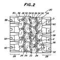
- Fig. 2 is a partial plan view of an embodiment of the heavy duty pneumatic tire according to the invention;
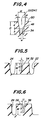
- Figs. 3a to 3c are schematically enlarged views of protrusions for the prevention of stone capturing at regions C, D and E in Fig. 2, respectively;
- Fig. 4 is a schematically section view of a circumferential groove provided with a protrusion for the prevention of stone capturing in the tire of Fig. 2;
- Figs. 5 and 6 are sectional views taken along lines V-V and VI-VI in Fig. 2, respectively;
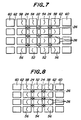
- Figs. 7 and 8 are schematic views of tread patterns in another embodiments of the heavy duty pneumatic tire according to the invention; and
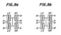
- Figs. 9a and 9b are schematic views showing a test method for the tire according to the invention and comparative tire.
- In the heavy duty pneumatic tire according to the invention, the projected part of the protrusion for the prevention of stone capturing, which is arranged at the intersect portion between the circumferential groove and the transverse groove dividing the island portion into blocks, projects toward the groove extending direction, so that such a projected part hinders the stone capturing at the intersect portion, and consequently there is not caused the stone capturing at the intersect portion and the tire damage due to the stone capturing can effectively be prevented.
- Furthermore, no cracking due to the reduction of the radius at the groove bottom is caused because the projected part is not extended along the transverse groove.
- Fig. 2 shows a tread pattern of a heavy duty
pneumatic tire 20 according to the invention, which comprises acircumferential groove 22 arranged on an equator of the tire and extending substantially along the equatorial plane in the circumferential direction twocircumferential grooves circumferential groove 22 and separated away from each other in the widthwise direction of the tire,transverse grooves 26 each arranged between thecircumferential grooves circumferential groove 22 at a constant angle with respect to the equatorial plane of the tire and separated from each other in the circumferential direction, and the othertransverse grooves 30 each slantly arranged between thecircumferential groove 24 and ashoulder portion 28 at a constant angle with respect to the equatorial plane of the tire and thecircumferential groove 24 and separated from each other. Moreover,numeral 32 is a narrow groove formed in theshoulder portion 28 so as to extend substantially in parallel to the equatorial plane of the tire, which acts to suppress the uneven wear of rubber blocks adjacent to theshoulder portion 28. - Onto the groove bottoms of the
circumferential grooves protrusions 34 for the prevention of stone capturing so as to separate away from each other in the circumferential direction of the tire along the groove extending direction. In this case, theseprotrusions 34 are arranged in at least intersect portion between thecircumferential groove 22 and thetransverse groove 26, intersect portion between thecircumferential groove 24 and thetransverse groove 26 and intersect portion between thecircumferential groove 24 and thetransverse groove 30, respectively. Of course, the top face of theprotrusion 34 for the prevention of stone capturing locates below the surface of the tread portion inward in the radial direction of the tire. - According to the invention, the
protrusion 34 disposed in the intersect portion between thecircumferential groove 22 and thetransverse groove 26 at a region C shown in Fig. 2 is provided with projectedparts 36 projecting toward the extending direction of thecircumferential groove 22 and projectedparts 38 projecting toward the extending direction of thetransverse groove 26 as shown in Fig. 3a. Furthermore, theprotrusion 34 disposed in the intersect portion between thecircumferential groove 24 and thetransverse groove 26 in a region D shown in Fig. 2 is provided with projectedparts 40 projecting toward the extending direction of thecircumferential groove 24 and projectedparts 42 projecting toward the extending direction of thetransverse groove 26 as shown in Fig. 3b. And also, theprotrusion 34 disposed in the intersect portion between thecircumferential groove 24 and thetransverse groove 30 in a region E shown in Fig. 2 is provided with projectedparts 44 projecting toward the extending direction of thecircumferential groove 24 and a projectedpart 46 projecting toward the extending direction of thetransverse groove 30 as shown in Fig. 3c. - In the heavy duty pneumatic tire according to the invention, the
protrusions 34 disposed in the intersect portions between thecircumferential groove 22 and thetransverse groove 26, between thecircumferential groove 24 and thetransverse groove 26 and betweencircumferential groove 24 and thetransverse groove 30, i.e. projected parts of these protrusions projecting toward the groove extending direction hinder the stone capturing at these intersect portions, so that the tire damage due to the stone capturing can effectively be prevented. - Furthermore, since each of the protrusions for the prevention of stone capturing has the projected part projecting toward the groove extending direction, the compression rigidity of the protrusion itself becomes high, so that the
protrusion 34 is not easily crushed even at the stone captured state, and consequently the discharge of captured stone can easily be made by elastic restoring force of the projected part during the running of the tire. - Moreover, the
protrusions 34 are arranged in thecircumferential grooves other protrusions 34a separated from each other in the groove extending direction are arranged between theprotrusions 34 each disposed at the intersect portion between thecircumferential groove 22 and thetransverse groove 26 along the bottom portion of thecircumferential groove 22, whereby the stone capturing is prevented in the portions of thecircumferential groove 22 other than the intersect portions. In addition, the projectedpart 36 of theprotrusion 34 disposed in the intersect portion may be connected to theprotrusion 34a disposed in thecircumferential groove 22 therealong. - In order to improve the wear resistance of the tire among some performances required in the heavy duty pneumatic tire, there is considered a method of making the depth of the groove in the tread portion deep, but in this case there is caused a problem that the stone capturing is apt to be easily caused.
- In Fig. 4 is partly shown the tread pattern of another embodiment of the heavy duty pneumatic tire according to the invention which can attain the desired effect of preventing the stone capturing by selecting the shape and size of the
protrusion 34 for the prevention of stone capturing with respect to thecircumferential groove 22. The tread pattern of this tire is the same as in the embodiment of Fig. 2, so that it is omitted for simplification other than the structure of the protrusion disposed in the circumferential groove. - The
opposed sidewalls 48 of the circumferential groove 22 (24) extend to a top of theprotrusion 34 for the stone capturing vertically disposed on the bottom of the circumferential groove or a height h of theprotrusion 34 perpendicular to thetread surface 50 and are enlarged from the vicinity of the top of theprotrusion 34 toward the tread surface at a given inclination angle α with respect to a plane perpendicular to the tread surface. - When the width of the circumferential groove 22 (24) at the
tread surface 50 is W, the depth of the circumferential groove 22 (24) from the tread surface is D, the depth from thetread surface 50 to the top of theprotrusion 34 is d and the height of theprotrusion 34 from the bottom of the circumferential groove 22 (24) is h, the shape and size of theprotrusion 34 are selected so that a ratio of the width W of the circumferential groove 22 (24) to the depth d of the protrusion d satisfies a relation of W/d ≧ 0.8 and a ratio of the height h of theprotrusion 34 to the depth D of the circumferential groove 22 (24) satisfies a relation of 0.4 ≦ h/D ≦ 0.5. - When the ratio W/d is less than 0.8, the stone capturing is apt to be caused. On the other hand, when the ratio h/D is less than 0.4, W/d becomes too small and the stone capturing is apt to be caused, while when it exceeds 0.5, the rigidity against the compression force of the
protrusion 34 becomes small and the desired effect of preventing the stone capturing and the drainage performance can not be developed. - In order to ensure the rigidity against the compression force of the
protrusion 34, the shape and size of theprotrusion 34 is preferably selected so that a ratio of the width w of theprotrusion 34 to the height h thereof satisfies a relation of w/h ≧ 0.2 and a ratio of length ℓ of the protrusion along the circumferential groove 22 (24) to the height h thereof satisfies a relation of ℓ/h ≧ 1.0. - In the preferred embodiment of the invention, in order to prevent the occurrence of shoulder wear in the shoulder portion and heel and toe wear in the remaining central portion in addition to the prevention of stone capturing, the heavy duty pneumatic tire has a tread pattern composed of at least five block rows defined by plural circumferential grooves and plural transverse grooves in the widthwise direction of the tire. In all of these block rows, each block is provided with a blind sipe formed along the circumferential direction of the tire so as not to arrive at each transverse groove. Alternatively, each shoulder block of a block row arranged at each end portion in widthwise direction of the tread has no sipe, while each center block of a block row arranged at a central portion in widthwise direction of the tread and each second block of a block row arranged between the shoulder block and the center block in widthwise direction of the tread are provided with a blind sipe formed along the circumferential direction of the tire so as not to arrive at each transverse groove.
- The mechanism of generating shoulder wear in the shoulder block is as follows. In the conventional tire, blind sipe has been formed in the shoulder block in addition to the center block and second block, so that the shearing force in circumferential direction was reduced in the braking and traction. On the other hand, if side force is applied to the tire, since the shoulder block is close to the input side of the side force, the motion of the tire in widthwise direction becomes considerably large as compared with the case of forming no sipe in the shoulder block. As a result, the wearing quantity (force x motion) of the shoulder block becomes large to generate the shoulder wear.
- In order to prevent the shoulder wear of the shoulder block, therefore, it is necessary to control the motion of the shoulder block. For this end, the blind sipe is not formed in the shoulder block according to the invention. If the blind sipe is formed in the shoulder block, it is necessary that a ratio of volume of the blind sipe to volume of the shoulder block containing such a blind sipe (sipe volume ratio) is not more than 0.5%. When the sipe volume ratio is more than 0.5%, the motion of the shoulder block under an influence of side force becomes large to cause the shoulder wear.
- Furthermore, it is preferable that the rubber constituting the shoulder block has a modulus at 300% elongation of 115-165 kgf/cm². When the modulus is less than 115 kgf/cm², the motion of the shoulder block under an influence of side force becomes too large, while when it exceeds 165 kgf/cm², the reaction force of the shoulder block under an influence of side force becomes large to make the wearing quantity large.
- On the other hand, the mechanism of generating the heel and toe wear in the center block and the second block is as follows. Since the ground contact pressure at the center block and the second block is higher than that of the shoulder block, the motion bearing in the braking and traction becomes larger in the center block and the second block than in the shoulder block. As a result, the shearing force in circumferential direction is large at the center block and the second block in the stepping-in and kicking-out and the wearing quantity becomes large to generate the heel and toe wear.
- In order to prevent the heel and toe wear of the center block and the second block in the stepping-in and kicking-out, therefore, it is necessary to control the shearing force in circumferential direction. For this end, blind sipe is formed in each of the center block and the second block according to the invention. In this case, a ratio of volume of the blind sipe to volume of the block containing such a blind sipe (sipe volume ratio) in each of the center block and the second block is within a range of 0.5-3.0%, preferably 1.2-1.7%. When the sipe volume ratio is less than 0.5%, the shearing force in circumferential direction can not sufficiently be reduced, while when it exceeds 3.0%, the shearing force in circumferential direction lowers, but the motion of the block as a whole becomes too large to increase the wearing quantity.
- Furthermore, it is preferable that the rubber constituting each of the center block and the second block has a modulus at 300% elongation of 90-140 kgf/cm². When the modulus is less than 90 kgf/cm², the shearing force in circumferential direction is sufficiently lowered, but the motion of the block becomes too large to increase the wearing quantity, while when it exceeds 140 kgf/cm², the sufficient reduction of the shearing force in circumferential direction can not be obtained. Moreover, the modulus at 300% elongation of rubber in the center block and the second block is higher than that of the shoulder block.
- According to the invention, the blind sipe to be formed in each of the center block, the second block and the shoulder block has a width of not more than 2.5 mm. When the width of the blind sipe exceeds 2.5 mm, the stone capturing is apt to be caused and also the difference in the rigidity around the blind sipe is large to cause the shoulder wear as well as the heel and toe wear. Furthermore, the blind sipe has a depth corresponding to 25-110%, preferably 70-80% of the height of each block. When the depth of the blind sipe is less than 25%, the period of holding the desired effect against the wearing of the tread becomes short, while when it exceeds 110%, the rubber thickness from the bottom of the blind sipe to the belt becomes too thin.
- The heavy duty pneumatic tire having a block pattern provided with the blind sipe according to the invention comprises a radial carcass toroidally extended between a pair of bead cores and wound around the bead core from inside of the tire to outside thereof, an inner surface of which is covered with an inner liner. Moreover, the radial carcass has a well-known structure composed of one or few rubberized plies containing cords arranged in the radial direction of the tire.
- The crown portion of the carcass is a tread portion having a thick gauge. Furthermore, the well-known non-extensible belt layer is disposed between the tread portion and the radial carcass to reinforce the tread portion.
- In the tread pattern of the tread portion in the heavy duty pneumatic
radial tire 20 as shown in Fig. 2, threecircumferential grooves transverse grooves 26 are arranged at approximately equal intervals in the circumferential direction of the tire so as to cross with at least a part of each of thecircumferential grooves circumferential groove transverse groove 26. - A
blind sipe 54 is formed in eachcenter block 52 of two block rows defined by thesecircumferential grooves transverse grooves 26 and located at a central portion of the tread in the widthwise direction of the tire. Theblind sipe 54 is located at the central portion of the center blook 52 in the widthwise direction of the tire along the circumferential direction of the tire. In this case, both end portions of the blind sipe are not opened to the respectivetransverse grooves 26 in the circumferential direction of the tire. And also, theblind sipe 54 is bent in accordance with the shape of thecenter block 52 in the circumferential direction of the tire. - As shown in Fig. 5, the depth N of the
blind sipe 54 is 76% of the depth M of thecircumferential groove 24, and the width L of theblind sipe 54 is 1.2 mm. Furthermore, the sipe volume ratio of theblind sipe 54 is 1.57% in thecenter block 52. - A block row of
second blocks 56 is arranged outside the row of the center blocks 52 in the widthwise direction of the tire. Ablind sipe 58 is formed in each of thesecond block 56. Thisblind sipe 58 is located at the central portion of thesecond block 56 in the widthwise direction of the tire along the circumferential direction of the tire. In this case, both end portions of the blind sipe are not opened to the respectivetransverse grooves 26 in the circumferential direction of the tire. And also, theblind sipe 58 is somewhat slanted in accordance with the shape of thesecond block 56 in the widthwise direction of the tire. - As shown in Fig. 6, the depth S of the
blind sipe 58 is 76% of the depth M of thecircumferential groove 24, and the width U of theblind sipe 58 is 1.2mm. Furthermore, the sipe volume ratio of theblind sipe 58 is 1.66% in thesecond block 56. - Further, a block row of shoulder blocks 60 is formed in each widthwise end portion of the tread. In the illustrated embodiment, the sipe is not formed in the
shoulder block 60. If the sipe is formed in theshoulder block 60, the sipe volume ratio should be not more than 0.5% in theshoulder block 60. - The each of the
center block 52 and thesecond block 56 is composed of a tread rubber having a modulus at 300% elongation of 115 kg/cm², and theshoulder block 60 is composed of a tread rubber having a modulus at 300% elongation of 141 kg/cm². - When the vehicle provided with such tires is at braking state or traction state, force is applied from road surface to the
center block 52,second block 56 andshoulder block 60. Since theblind sipes center block 52 and thesecond block 56 having a given modulus at 300% elongation at a given sipe volume ratio, the ground contact pressure is lowered at thecenter block 52 and thesecond block 56, whereby the increase of shearing force in circumferential direction at stepping-in and kicking-out is prevented and consequently the wearing quantity at these blocks becomes small to control the occurrence of heel and toe wear. - On the other hand, when the vehicle is at cornering state, a large side force is applied to the
shoulder block 60 located at the input side of the side force. Since the shoulder block has a given modulus at 300% elongation and is not provided with a sipe or even if the sipe is formed in the shoulder block, the sipe volume ration is restricted to not more than 0.5%, the motion of theshoulder block 60 in the widthwise direction of the tire is lowered and hence the wearing quantity becomes small to control the shoulder wear. - Another embodiment of the heavy duty pneumatic tire according to the invention has a tread pattern as shown in Fig. 7. In this case, the tread portion is divided into six rectangular block rows by five
circumferential grooves transverse grooves 26 located at given intervals in the circumferential direction of the tire. In this embodiment, the same effect as in the aforementioned embodiment is obtained. - The other embodiment of the heavy duty pneumatic tire according to the invention has a tread pattern as shown in Fig. 8. In this case, the tread portion is divided into five rectangular block rows by four
circumferential grooves transverse grooves 26 located at given intervals in the circumferential direction of the tire. In this embodiment, the center blocks 52 form a single block row, but the same effect as in the aforementioned embodiment is obtained. - The following examples are given in illustration of the invention and are not intended as limitations thereof.
- This example shows the comparison in the performance of preventing stone capturing between the heavy duty pneumatic tire according to the invention and the conventional heavy duty pneumatic tire.
- Tire having a tire size of 285/75 R24.5 and a general radial structure
- This tire has a tread pattern shown in Fig. 2, wherein the width W and depth D of the
circumferential groove 22 are 12.0 mm and 22.0 mm, respectively, and the depth d, height h and width w of theprotrusion 34 for the prevention of stone capturing are 12.4 mm, 9.6 mm and 2.5 mm, respectively; and the width W and depth D of thecircumferential groove 24 separated from thecircumferential groove 22 at a distance of 29.4 mm are 13.0 mm and 25.0 mm, respectively, and the depth d, height h and width w of theprotrusion 34 are 13.4 mm, 11.6 mm and 2.5 mm, respectively; the width and depth of thetransverse groove 26 disposed at an interval of 50.1 mm in the circumferential direction of the tire and slantly crossing with the circumferential groove along the equatorial plane of the tire are 7.0 mm and 22.0 mm, respectively; and the width and depth of thetransverse groove 30 disposed at an interval of 45.5 mm in the circumferential direction and slantly crossing with the circumferential groove are 11.0 mm and 25.0 mm, respectively. - Since the width W of the
circumferential groove 22 is narrower by 1 mm than that of thecircumferential groove 24, if the depths d of these circumferential grooves are the same, the performance of preventing the stone capturing in thecircumferential groove 22 is poorer than that of thecircumferential groove 24. For this end, the performance of preventing the stone capturing in thecircumferential groove 22 is ensured to be equal to that of thecircumferential groove 24 by making the depth of the protrusion in thecircumferential groove 22 shallower than that in thecircumferential groove 24. In this case, if the depth of thecircumferential groove 22 is equal to that (25.0 mm) of thecircumferential groove 24, the ratio (h/D) of height h of the protrusion to the depth D of the circumferential groove is 0.504, which is outside the range of 0.4 ≦ h/D ≦ 0.5 defined in the invention, so that the depth D of thecircumferential groove 22 is shallowed to 22.0 mm. - When the tire is mounted onto a driving shaft, the heel and toe wear is apt to be caused due to the motion of rubber blocks in the central portion of the tread based on the traction force. In the invention tire, the depth D of the
circumferential groove 22 is shallower than that of thecircumferential groove 24, so that the rigidity of rubber blocks in the central portion of the tread becomes higher than the rigidity of rubber blocks in the other portion of the tread to control the motion of rubber blocks in the central portion of the tread, whereby the occurrence of uneven wear can effectively be prevented. - The invention tire having the protrusion for the prevention of stone capturing in the intersect portion between the grooves has naturally a sufficient performance for the prevention of stone capturing as compared with the conventional tire even when the depth D of the
circumferential groove 22 is equal to that of thecircumferential groove 24. - This tire has a tread pattern provided with the protrusion for the prevention of stone capturing as shown in Figs. 1a and 1b. In this case, the width at tread surface W₀, width at bottom and depth D₀ of the
circumferential groove 12 are 12.0 mm, 10.5 mm and 22.0 mm, respectively, and the depth d₀, height h₀ and width w₀ of the protrusion are 16.0 mm, 6.0 mm and 6.0 mm, respectively; the width W₀, width at bottom and depth D₀ of thecircumferential groove 18 separated from thecircumferential groove 12 at a distance of 29.4 mm are 13.0 mm, 10.5 mm and 25.0 mm, respectively, and the depth d₀, height h₀ and width w₀ of the protrusion are 19.0 mm, 6.0 mm and 4.4 mm, respectively; the width and depth of the transverse groove disposed at an interval of 50.1 mm in the circumferential direction of the tire and slantly crossing with the circumferential groove along the equatorial plane of the tire are 7.0 mm and 22.0 mm, respectively; and the width and depth of the transverse groove disposed at an interval of 45.5 mm in the circumferential direction of the tire and slantly crossing with the circumferential groove along the equatorial plane of the tire are 11.0 mm and 25.0 mm, respectively. - The invention tire and the conventional tire are mounted onto front wheel and rear wheel in the same vehicle and actually run over a distance of 20,000 km, and thereafter the number of captured stones per one tire was measured by an index on the basis that the conventional tire is 100.
- Moreover, in order to make the test conditions same, the invention tire (A) and the conventional tire (B) were alternately mounted onto a front right side (RF), a front left side (LF), a rear right side (RR) and a rear left side (LR) in the running direction of the vehicle as shown in Figs. 4a and 4b.
- The measured results are shown in Table 1. Moreover, the smaller the index value, the better the performance for the prevention of stone capturing.
Table 1 Invention tire Conventional tire Evaluation 70 100 - As seen from Table 1, according to the invention tire, the performance for the prevention of stone capturing is largely improved as compared with the conventional tire.
- There were provided two test tires having a tire size of 285/75 R24.5, one of which tires being the invention tire having a tread pattern as shown in Figs. 2, 5 and 6 and the other being the conventional tire having the same tread pattern as in the invention tire except that each block has no blind sipe. Each of these test tires was mounted onto a normal rim and run on general road under normal internal pressure and load over a distance of 100,000 km, and thereafter the worn state was measured to obtain results as shown in the following Table 2.
Table 2 Kind of tire Conventional tire Invention tire Stepwise difference of heel and toe wear 4.0 mm 1.5 mm Shoulder wear width × stepwise difference 15 mm × 2.4 mm 2 mm × 1.5 mm - As seen from Table 2, the stepwise difference of heel and toe wear in the heavy duty pneumatic radial tire according to the invention is smaller than that of the conventional tire having no blind sipe, while the shoulder wear width x stepwise difference thereof in the tire according to the invention are smaller than those of the conventional tire. As a result, the tire according to the invention is superior to the conventional tire in the wear resistance in addition to the prevention of stone capturing.
- As mentioned above, according to the invention, the performance for the prevention of stone capturing can considerably be improved and also the shoulder wear in the shoulder portion and the heel and toe wear in the central portion can effectively be prevented.
Claims (11)
characterized in that, when the width at the tread surface (50) and the depth of said circumferential groove (22, 24) are W and D and the depth from the tread surface to the top of said protrusion is d and the height of said protrusion from the groove bottom of said circumferential groove is d, said circumferential groove and protrusion satisfy relations of W/d ≧ 0.8 and 0.4 ≦ h/D ≦ 0.5.
characterized in that said tread has a block pattern composed of at least five block rows defined by a plurality of circumferential grooves and a plurality of transverse grooves in the widthwise directon of the tire.
characterised in that each block in all of said block rows is provided with a blind sipe (54, 58) formed along the circumferential direction of the tire so as not to arrive at each transverse groove.
characterized in that each centre block (52) of a block row arranged at a central portion in the widthwise direction of the tread and each second block (56) of a block row arranged between a shoulder block (60) and the centre block in the widthwise direction of the tread are provided with a blind sipe (54, 58) formed along the circumferential direction of the tire so as not to arrive at each transverse groove.
characterized in that said blind sipe has a width of not more than 2.5mm.
characterized in that said blind sipe has a depth corresponding to 25-110% of a height of said block.
characterized in that the volume of said blind sipe in each block of a shoulder block row among said block rows is not more than 0.5% of the volume of said block, and the volume of said blind sipe in each block of centre and second block rows among said block rows is 0.5-3.0% of the volume of said block.
characterized in that the volume of said blind sipe in each block of centre and second block rows among said block rows is 0.5-3.0% of the volume of said block.
characterized in that each block in said centre and second block rows is made from rubber having a modulus at 300% elongation of 90-110 kg/cm², and each block in said shoulder block row is made from rubber having a modulus at 300% elongation of 115-165 kg/cm².
characterized in that said modulus in said centre and second block rows is larger than that of said shoulder block row.
Applications Claiming Priority (6)
| Application Number | Priority Date | Filing Date | Title |
|---|---|---|---|
| JP203805/89 | 1989-08-08 | ||
| JP1203805A JPH0367706A (en) | 1989-08-08 | 1989-08-08 | Pneumatic tire for heavy load |
| JP214556/89 | 1989-08-21 | ||
| JP1214556A JP2874769B2 (en) | 1989-08-21 | 1989-08-21 | Pneumatic radial tire for heavy loads |
| JP214555/89 | 1989-08-21 | ||
| JP1214555A JPH0379405A (en) | 1989-08-21 | 1989-08-21 | Pneumatic tire filled with air for heavy load |
Publications (2)
| Publication Number | Publication Date |
|---|---|
| EP0413502A1 true EP0413502A1 (en) | 1991-02-20 |
| EP0413502B1 EP0413502B1 (en) | 1993-11-03 |
Family
ID=27328286
Family Applications (1)
| Application Number | Title | Priority Date | Filing Date |
|---|---|---|---|
| EP90308723A Expired - Lifetime EP0413502B1 (en) | 1989-08-08 | 1990-08-08 | Heavy duty pneumatic tires |
Country Status (4)
| Country | Link |
|---|---|
| US (1) | US5160385A (en) |
| EP (1) | EP0413502B1 (en) |
| DE (1) | DE69004378T2 (en) |
| ES (1) | ES2047859T3 (en) |
Cited By (9)
| Publication number | Priority date | Publication date | Assignee | Title |
|---|---|---|---|---|
| EP0598300A1 (en) * | 1992-11-16 | 1994-05-25 | The Goodyear Tire & Rubber Company | A tread for a tire |
| EP0904960A2 (en) * | 1997-09-30 | 1999-03-31 | Sumitomo Rubber Industries Limited | Studless tyre |
| WO2000029228A1 (en) * | 1998-11-18 | 2000-05-25 | The Goodyear Tire & Rubber Company | Tread/tire with improved groove design |
| CN103260904A (en) * | 2010-12-23 | 2013-08-21 | 倍耐力轮胎股份公司 | Tyre for heavy load vehicle wheels |
| US8776847B2 (en) | 2007-12-21 | 2014-07-15 | Michelin Recherche Et Technique S.A. | Mechanisms for ejecting objects from a tire tread |
| WO2018019449A1 (en) * | 2016-07-26 | 2018-02-01 | Continental Reifen Deutschland Gmbh | Vehicle tire |
| CN107878119A (en) * | 2016-09-29 | 2018-04-06 | 住友橡胶工业株式会社 | Tire |
| CN110366497A (en) * | 2017-02-23 | 2019-10-22 | 大陆轮胎德国有限公司 | Pneumatic vehicle tire |
| EP3771574A1 (en) * | 2019-07-30 | 2021-02-03 | Sumitomo Rubber Industries, Ltd. | Heavy duty pneumatic tire |
Families Citing this family (34)
| Publication number | Priority date | Publication date | Assignee | Title |
|---|---|---|---|---|
| CA2023538C (en) * | 1990-05-17 | 2000-01-11 | Jean Francois Leon Fontaine | Tread for a pneumatic tire |
| JP3193169B2 (en) * | 1992-12-22 | 2001-07-30 | 住友ゴム工業株式会社 | Pneumatic tires for heavy vehicles |
| DE4410999A1 (en) * | 1994-03-30 | 1995-10-05 | Continental Ag | Vehicle tires with a stone deflector |
| USD384623S (en) * | 1996-05-14 | 1997-10-07 | The Goodyear Tire & Rubber Company | Tire tread |
| USD384608S (en) * | 1996-05-14 | 1997-10-07 | The Goodyear Tire & Rubber Company | Tire tread |
| US6176284B1 (en) * | 1996-07-19 | 2001-01-23 | Sumitomo Rubber Industries, Ltd. | Pneumatic tire |
| US6000451A (en) * | 1996-07-19 | 1999-12-14 | Sumitomo Rubber Industries, Ltd. | Pneumatic tire including at least one projection |
| JP3507634B2 (en) * | 1996-10-01 | 2004-03-15 | 住友ゴム工業株式会社 | Pneumatic tire |
| DE19700101A1 (en) * | 1997-01-03 | 1998-07-09 | Pirelli Reifenwerke | Tread pattern for a vehicle tire |
| USD388034S (en) * | 1997-01-31 | 1997-12-23 | The Goodyear Tire & Rubber Company | Tire tread |
| USD432960S (en) * | 1998-11-12 | 2000-10-31 | The Goodyear Tire & Rubber Company | Tire tread |
| JP4267735B2 (en) * | 1998-12-14 | 2009-05-27 | 株式会社ブリヂストン | Pneumatic tire |
| USD421944S (en) * | 1999-05-28 | 2000-03-28 | The Goodyear Tire & Rubber Company | Tire tread |
| USD423421S (en) * | 1999-08-17 | 2000-04-25 | The Goodyear Tire & Rubber Company | Tire tread |
| USD425830S (en) * | 1999-08-17 | 2000-05-30 | The Goodyear Tire & Rubber Company | Tire tread |
| USD427552S (en) * | 1999-08-24 | 2000-07-04 | The Goodyear Tire & Rubber Company | Tire tread |
| FR2800326A1 (en) * | 1999-10-29 | 2001-05-04 | Michelin Soc Tech | TREAD SCULPTURE FOR HIGH LOAD CAPACITY VEHICLE TIRES |
| USD430832S (en) * | 1999-12-21 | 2000-09-12 | Bridgestone/Firestone Research, Inc. | Tire tread |
| EP1207058B1 (en) * | 2000-11-13 | 2007-06-06 | Société de Technologie Michelin | Tread pattern for radial pneumatic tyre |
| US7096904B2 (en) * | 2002-12-26 | 2006-08-29 | The Goodyear Tire & Rubber Company | Off road tire having variable width puncture preventing pads |
| JP4462001B2 (en) * | 2004-10-18 | 2010-05-12 | 横浜ゴム株式会社 | Pneumatic tire |
| JP5011880B2 (en) * | 2005-09-21 | 2012-08-29 | 横浜ゴム株式会社 | Pneumatic tire |
| JP4959255B2 (en) * | 2006-08-22 | 2012-06-20 | 東洋ゴム工業株式会社 | Pneumatic tire and manufacturing method thereof |
| DE102007032226B4 (en) * | 2007-07-11 | 2016-07-07 | Continental Reifen Deutschland Gmbh | Vehicle tires |
| FR2971732B1 (en) * | 2011-02-17 | 2013-02-01 | Michelin Soc Tech | TIRE TREAD FOR PNEUMATIC HEAVY DUTY TRAILER TYPE AND MOLDING ELEMENT |
| JP5841572B2 (en) * | 2013-08-05 | 2016-01-13 | 住友ゴム工業株式会社 | Heavy duty tire |
| CN105960341A (en) | 2014-02-04 | 2016-09-21 | 普利司通美国轮胎运营有限责任公司 | Radial stone ejectors |
| JP6114731B2 (en) * | 2014-10-31 | 2017-04-12 | 住友ゴム工業株式会社 | Pneumatic tire |
| JP6367692B2 (en) | 2014-11-18 | 2018-08-01 | 東洋ゴム工業株式会社 | Pneumatic tire |
| WO2018044292A1 (en) * | 2016-08-31 | 2018-03-08 | Compagnie Generale Des Establissements Michelin | Heavy truck tire tread and heavy truck tire |
| WO2019088987A1 (en) * | 2017-10-31 | 2019-05-09 | Compagnie Generale Des Etablissements Michelin | Tread for a heavy truck tire |
| JP7104573B2 (en) | 2018-06-26 | 2022-07-21 | Toyo Tire株式会社 | Pneumatic tires |
| KR102088907B1 (en) * | 2018-11-21 | 2020-03-13 | 금호타이어 주식회사 | Heavy duty pneumatic tire |
| JP7393639B2 (en) * | 2020-01-17 | 2023-12-07 | 横浜ゴム株式会社 | tire |
Family Cites Families (13)
| Publication number | Priority date | Publication date | Assignee | Title |
|---|---|---|---|---|
| BE384271A (en) * | 1930-11-20 | |||
| GB755137A (en) * | 1953-08-21 | 1956-08-15 | Firestone Tire & Rubber Co | Improvements in or relating to tire construction |
| US3926238A (en) * | 1971-08-31 | 1975-12-16 | Gates Rubber Co | Modulating noise produced by rotating bodies |
| JPS595443B2 (en) * | 1979-11-29 | 1984-02-04 | 株式会社ブリヂストン | Pneumatic tires for heavy loads |
| JPS60189608A (en) * | 1984-03-09 | 1985-09-27 | Yokohama Rubber Co Ltd:The | Pneumatic tire |
| JPS60234005A (en) * | 1984-05-02 | 1985-11-20 | Bridgestone Corp | Pneumatic tire excellent for wettability |
| JPS611508A (en) * | 1984-06-13 | 1986-01-07 | Sumitomo Rubber Ind Ltd | Radial tire for truck or bus |
| JPS61111804U (en) * | 1984-12-27 | 1986-07-15 | ||
| JPS61291203A (en) * | 1985-06-20 | 1986-12-22 | Bridgestone Corp | Tread pattern preventing from sinking of stone |
| JPH0662042B2 (en) * | 1986-02-22 | 1994-08-17 | 住友ゴム工業株式会社 | Pneumatic tires for heavy vehicles |
| JPS63106110A (en) * | 1986-10-23 | 1988-05-11 | Bridgestone Corp | Radial tyre for heavy load |
| JP2652860B2 (en) * | 1987-12-21 | 1997-09-10 | 横浜ゴム株式会社 | Rubber composition for tire tread |
| JPH02293204A (en) * | 1989-05-09 | 1990-12-04 | Bridgestone Corp | Pneumatic tire for winter |
-
1990
- 1990-08-06 US US07/562,984 patent/US5160385A/en not_active Expired - Lifetime
- 1990-08-08 EP EP90308723A patent/EP0413502B1/en not_active Expired - Lifetime
- 1990-08-08 ES ES90308723T patent/ES2047859T3/en not_active Expired - Lifetime
- 1990-08-08 DE DE90308723T patent/DE69004378T2/en not_active Expired - Fee Related
Non-Patent Citations (3)
| Title |
|---|
| PATENT ABSTRACTS OF JAPAN vol. 10, no. 37 (M-453)(2094) 14 February 1986, & JP-A-60 189608 (YOKOHAMA GOMU K.K.) 27 September 1985, * |
| PATENT ABSTRACTS OF JAPAN vol. 11, no. 158 (M-591)(2605) 22 May 1987, & JP-A-61 291203 (BRIDGESTONE CORPORATION) 22 December 1986, * |
| PATENT ABSTRACTS OF JAPAN vol. 12, no. 41 (M-666)(2888) 06 February 1988, & JP-A-62 194908 (SUMITOMO RUBBER IND. LTD.) 27 August 1987, * |
Cited By (17)
| Publication number | Priority date | Publication date | Assignee | Title |
|---|---|---|---|---|
| EP0598300A1 (en) * | 1992-11-16 | 1994-05-25 | The Goodyear Tire & Rubber Company | A tread for a tire |
| US5361815A (en) * | 1992-11-16 | 1994-11-08 | The Goodyear Tire & Rubber Company | Tread for a tire with blocks and ribs |
| TR28130A (en) * | 1992-11-16 | 1996-02-13 | Goodyear Tire & Rubber | Rolling surface for tire. |
| EP0904960A2 (en) * | 1997-09-30 | 1999-03-31 | Sumitomo Rubber Industries Limited | Studless tyre |
| EP0904960A3 (en) * | 1997-09-30 | 2000-11-02 | Sumitomo Rubber Industries Limited | Studless tyre |
| WO2000029228A1 (en) * | 1998-11-18 | 2000-05-25 | The Goodyear Tire & Rubber Company | Tread/tire with improved groove design |
| US8776847B2 (en) | 2007-12-21 | 2014-07-15 | Michelin Recherche Et Technique S.A. | Mechanisms for ejecting objects from a tire tread |
| CN103260904A (en) * | 2010-12-23 | 2013-08-21 | 倍耐力轮胎股份公司 | Tyre for heavy load vehicle wheels |
| WO2018019449A1 (en) * | 2016-07-26 | 2018-02-01 | Continental Reifen Deutschland Gmbh | Vehicle tire |
| CN109476186A (en) * | 2016-07-26 | 2019-03-15 | 大陆轮胎德国有限公司 | Vehicle tyre |
| CN109476186B (en) * | 2016-07-26 | 2021-01-01 | 大陆轮胎德国有限公司 | Vehicle tyre |
| US11453248B2 (en) | 2016-07-26 | 2022-09-27 | Continental Reifen Deutschland Gmbh | Vehicle tire |
| CN107878119A (en) * | 2016-09-29 | 2018-04-06 | 住友橡胶工业株式会社 | Tire |
| CN107878119B (en) * | 2016-09-29 | 2022-02-11 | 住友橡胶工业株式会社 | Tyre for vehicle wheels |
| CN110366497A (en) * | 2017-02-23 | 2019-10-22 | 大陆轮胎德国有限公司 | Pneumatic vehicle tire |
| US11565553B2 (en) | 2017-02-23 | 2023-01-31 | Continental Reifen Deutschland Gmbh | Pneumatic vehicle tyre |
| EP3771574A1 (en) * | 2019-07-30 | 2021-02-03 | Sumitomo Rubber Industries, Ltd. | Heavy duty pneumatic tire |
Also Published As
| Publication number | Publication date |
|---|---|
| ES2047859T3 (en) | 1994-03-01 |
| DE69004378T2 (en) | 1994-03-10 |
| EP0413502B1 (en) | 1993-11-03 |
| DE69004378D1 (en) | 1993-12-09 |
| US5160385A (en) | 1992-11-03 |
Similar Documents
| Publication | Publication Date | Title |
|---|---|---|
| EP0413502B1 (en) | Heavy duty pneumatic tires | |
| US6116309A (en) | Tread for a tire including five rib parts | |
| EP0313361B1 (en) | Heavy duty pneumatic tires preventing uneven wearing | |
| EP0233135B1 (en) | All-season pneumatic tire with chamfered tread blocks | |
| EP0598300B1 (en) | A tread for a tire | |
| EP0904960B1 (en) | Studless tyre | |
| US4446901A (en) | Heavy duty pneumatic radial tires | |
| EP0710577A1 (en) | Pneumatic radial tire | |
| JP3515296B2 (en) | Heavy duty pneumatic tires | |
| CN111497527A (en) | Pneumatic tire | |
| EP0235072A2 (en) | All-season pneumatic tire with improved tread stiffness | |
| EP0318287A2 (en) | Heavy duty pneumatic radial tires | |
| EP3828011B1 (en) | Tyre tread | |
| US6102093A (en) | Pneumatic tire including long blocks and wide blocks | |
| EP0936088B1 (en) | Pneumatic tyre | |
| JPH05178031A (en) | Pneumatic tire | |
| JPH05178015A (en) | Pneumatic radial tire for heavy load | |
| EP1813446B1 (en) | Pneumatic tire | |
| EP0468815B1 (en) | Pneumatic tires | |
| JPH0834205A (en) | Pneumatic tire | |
| EP0689946B1 (en) | Pneumatic tires | |
| JPH0848115A (en) | Pneumatic radial tire | |
| JPH06297917A (en) | Pneumatic radial tire | |
| JP2000238507A (en) | Tire for heavy loarding | |
| US20230311576A1 (en) | Tire |
Legal Events
| Date | Code | Title | Description |
|---|---|---|---|
| PUAI | Public reference made under article 153(3) epc to a published international application that has entered the european phase |
Free format text: ORIGINAL CODE: 0009012 |
|
| AK | Designated contracting states |
Kind code of ref document: A1 Designated state(s): DE ES FR LU |
|
| 17P | Request for examination filed |
Effective date: 19910313 |
|
| 17Q | First examination report despatched |
Effective date: 19920923 |
|
| GRAA | (expected) grant |
Free format text: ORIGINAL CODE: 0009210 |
|
| AK | Designated contracting states |
Kind code of ref document: B1 Designated state(s): DE ES FR LU |
|
| REF | Corresponds to: |
Ref document number: 69004378 Country of ref document: DE Date of ref document: 19931209 |
|
| ET | Fr: translation filed | ||
| REG | Reference to a national code |
Ref country code: ES Ref legal event code: FG2A Ref document number: 2047859 Country of ref document: ES Kind code of ref document: T3 |
|
| PLBE | No opposition filed within time limit |
Free format text: ORIGINAL CODE: 0009261 |
|
| STAA | Information on the status of an ep patent application or granted ep patent |
Free format text: STATUS: NO OPPOSITION FILED WITHIN TIME LIMIT |
|
| 26N | No opposition filed | ||
| PGFP | Annual fee paid to national office [announced via postgrant information from national office to epo] |
Ref country code: LU Payment date: 19951001 Year of fee payment: 6 |
|
| PG25 | Lapsed in a contracting state [announced via postgrant information from national office to epo] |
Ref country code: LU Free format text: LAPSE BECAUSE OF NON-PAYMENT OF DUE FEES Effective date: 19960808 |
|
| PGFP | Annual fee paid to national office [announced via postgrant information from national office to epo] |
Ref country code: FR Payment date: 19960809 Year of fee payment: 7 |
|
| PGFP | Annual fee paid to national office [announced via postgrant information from national office to epo] |
Ref country code: DE Payment date: 19960816 Year of fee payment: 7 |
|
| PGFP | Annual fee paid to national office [announced via postgrant information from national office to epo] |
Ref country code: ES Payment date: 19960830 Year of fee payment: 7 |
|
| PG25 | Lapsed in a contracting state [announced via postgrant information from national office to epo] |
Ref country code: ES Free format text: LAPSE BECAUSE OF THE APPLICANT RENOUNCES Effective date: 19970809 |
|
| PG25 | Lapsed in a contracting state [announced via postgrant information from national office to epo] |
Ref country code: FR Free format text: LAPSE BECAUSE OF NON-PAYMENT OF DUE FEES Effective date: 19980430 |
|
| PG25 | Lapsed in a contracting state [announced via postgrant information from national office to epo] |
Ref country code: DE Free format text: LAPSE BECAUSE OF NON-PAYMENT OF DUE FEES Effective date: 19980501 |
|
| REG | Reference to a national code |
Ref country code: FR Ref legal event code: ST |
|
| REG | Reference to a national code |
Ref country code: ES Ref legal event code: FD2A Effective date: 20001102 |