EP0233135B1 - All-season pneumatic tire with chamfered tread blocks - Google Patents
All-season pneumatic tire with chamfered tread blocks Download PDFInfo
- Publication number
- EP0233135B1 EP0233135B1 EP87630015A EP87630015A EP0233135B1 EP 0233135 B1 EP0233135 B1 EP 0233135B1 EP 87630015 A EP87630015 A EP 87630015A EP 87630015 A EP87630015 A EP 87630015A EP 0233135 B1 EP0233135 B1 EP 0233135B1
- Authority
- EP
- European Patent Office
- Prior art keywords
- tread
- grooves
- tire
- rubber
- blocks
- Prior art date
- Legal status (The legal status is an assumption and is not a legal conclusion. Google has not performed a legal analysis and makes no representation as to the accuracy of the status listed.)
- Expired - Lifetime
Links
Images


Classifications
-
- B—PERFORMING OPERATIONS; TRANSPORTING
- B61—RAILWAYS
- B61C—LOCOMOTIVES; MOTOR RAILCARS
- B61C11/00—Locomotives or motor railcars characterised by the type of means applying the tractive effort; Arrangement or disposition of running gear other than normal driving wheel
-
- B—PERFORMING OPERATIONS; TRANSPORTING
- B60—VEHICLES IN GENERAL
- B60C—VEHICLE TYRES; TYRE INFLATION; TYRE CHANGING; CONNECTING VALVES TO INFLATABLE ELASTIC BODIES IN GENERAL; DEVICES OR ARRANGEMENTS RELATED TO TYRES
- B60C11/00—Tyre tread bands; Tread patterns; Anti-skid inserts
- B60C11/03—Tread patterns
- B60C11/13—Tread patterns characterised by the groove cross-section, e.g. for buttressing or preventing stone-trapping
- B60C11/1369—Tie bars for linking block elements and bridging the groove
-
- B—PERFORMING OPERATIONS; TRANSPORTING
- B60—VEHICLES IN GENERAL
- B60C—VEHICLE TYRES; TYRE INFLATION; TYRE CHANGING; CONNECTING VALVES TO INFLATABLE ELASTIC BODIES IN GENERAL; DEVICES OR ARRANGEMENTS RELATED TO TYRES
- B60C11/00—Tyre tread bands; Tread patterns; Anti-skid inserts
- B60C11/03—Tread patterns
- B60C11/0302—Tread patterns directional pattern, i.e. with main rolling direction
-
- B—PERFORMING OPERATIONS; TRANSPORTING
- B60—VEHICLES IN GENERAL
- B60C—VEHICLE TYRES; TYRE INFLATION; TYRE CHANGING; CONNECTING VALVES TO INFLATABLE ELASTIC BODIES IN GENERAL; DEVICES OR ARRANGEMENTS RELATED TO TYRES
- B60C11/00—Tyre tread bands; Tread patterns; Anti-skid inserts
- B60C11/03—Tread patterns
- B60C11/0306—Patterns comprising block rows or discontinuous ribs
- B60C11/0309—Patterns comprising block rows or discontinuous ribs further characterised by the groove cross-section
-
- B—PERFORMING OPERATIONS; TRANSPORTING
- B60—VEHICLES IN GENERAL
- B60C—VEHICLE TYRES; TYRE INFLATION; TYRE CHANGING; CONNECTING VALVES TO INFLATABLE ELASTIC BODIES IN GENERAL; DEVICES OR ARRANGEMENTS RELATED TO TYRES
- B60C11/00—Tyre tread bands; Tread patterns; Anti-skid inserts
- B60C11/03—Tread patterns
- B60C11/0327—Tread patterns characterised by special properties of the tread pattern
- B60C11/033—Tread patterns characterised by special properties of the tread pattern by the void or net-to-gross ratios of the patterns
-
- B—PERFORMING OPERATIONS; TRANSPORTING
- B60—VEHICLES IN GENERAL
- B60C—VEHICLE TYRES; TYRE INFLATION; TYRE CHANGING; CONNECTING VALVES TO INFLATABLE ELASTIC BODIES IN GENERAL; DEVICES OR ARRANGEMENTS RELATED TO TYRES
- B60C11/00—Tyre tread bands; Tread patterns; Anti-skid inserts
- B60C11/03—Tread patterns
- B60C11/11—Tread patterns in which the raised area of the pattern consists only of isolated elements, e.g. blocks
-
- B—PERFORMING OPERATIONS; TRANSPORTING
- B60—VEHICLES IN GENERAL
- B60C—VEHICLE TYRES; TYRE INFLATION; TYRE CHANGING; CONNECTING VALVES TO INFLATABLE ELASTIC BODIES IN GENERAL; DEVICES OR ARRANGEMENTS RELATED TO TYRES
- B60C11/00—Tyre tread bands; Tread patterns; Anti-skid inserts
- B60C11/03—Tread patterns
- B60C11/13—Tread patterns characterised by the groove cross-section, e.g. for buttressing or preventing stone-trapping
- B60C11/1376—Three dimensional block surfaces departing from the enveloping tread contour
- B60C11/1384—Three dimensional block surfaces departing from the enveloping tread contour with chamfered block corners
-
- B—PERFORMING OPERATIONS; TRANSPORTING
- B60—VEHICLES IN GENERAL
- B60C—VEHICLE TYRES; TYRE INFLATION; TYRE CHANGING; CONNECTING VALVES TO INFLATABLE ELASTIC BODIES IN GENERAL; DEVICES OR ARRANGEMENTS RELATED TO TYRES
- B60C11/00—Tyre tread bands; Tread patterns; Anti-skid inserts
- B60C11/03—Tread patterns
- B60C2011/0337—Tread patterns characterised by particular design features of the pattern
- B60C2011/0386—Continuous ribs
- B60C2011/0388—Continuous ribs provided at the equatorial plane
-
- B—PERFORMING OPERATIONS; TRANSPORTING
- B60—VEHICLES IN GENERAL
- B60C—VEHICLE TYRES; TYRE INFLATION; TYRE CHANGING; CONNECTING VALVES TO INFLATABLE ELASTIC BODIES IN GENERAL; DEVICES OR ARRANGEMENTS RELATED TO TYRES
- B60C11/00—Tyre tread bands; Tread patterns; Anti-skid inserts
- B60C11/03—Tread patterns
- B60C11/12—Tread patterns characterised by the use of narrow slits or incisions, e.g. sipes
- B60C11/1204—Tread patterns characterised by the use of narrow slits or incisions, e.g. sipes with special shape of the sipe
- B60C2011/1213—Tread patterns characterised by the use of narrow slits or incisions, e.g. sipes with special shape of the sipe sinusoidal or zigzag at the tread surface
-
- Y—GENERAL TAGGING OF NEW TECHNOLOGICAL DEVELOPMENTS; GENERAL TAGGING OF CROSS-SECTIONAL TECHNOLOGIES SPANNING OVER SEVERAL SECTIONS OF THE IPC; TECHNICAL SUBJECTS COVERED BY FORMER USPC CROSS-REFERENCE ART COLLECTIONS [XRACs] AND DIGESTS
- Y10—TECHNICAL SUBJECTS COVERED BY FORMER USPC
- Y10S—TECHNICAL SUBJECTS COVERED BY FORMER USPC CROSS-REFERENCE ART COLLECTIONS [XRACs] AND DIGESTS
- Y10S152/00—Resilient tires and wheels
- Y10S152/902—Non-directional tread pattern having no circumferential rib and having blocks defined by circumferential grooves and transverse grooves
Definitions
- This invention relates to an all-season radial-ply pneumatic tire for passenger and light-truck vehicles as described for instance in US-A-4 619 300.
- An all-season pneumatic tire is regarded as one which currently qualifies for a mud and snow (M&S) rating under the criteria for such rating established by the Rubber Manufacturers Association, Akron, Ohio.
- M&S mud and snow
- such rating requires that the tire tread have full-depth grooves that are angled laterally toward the respective lateral edges of the tread surface for at least one-half inch and such grooves are required to have a width of at least 0.060 inch.
- All-season tires are characterized by grooves that define blocks, and sometimes one or more ribs, in the tread surface. This results in a more aggressive appearance than that of a more conventional fully-ribbed tire and provides improved traction characteristics in snow and under wet conditions as compared to the conventional ribbed tire. All-season tires are distinguished from snow tires in that the former are required to satisfy all Federal Motor Vehicle Safety Standard 109 tests applicable to radial passenger tires in general, but the latter are not required to satisfy the provisions in such standards relating to high-speed test performance.
- All-season tires customarily employ block elements in their tread designs.
- the block elements are surrounded by grooves typically having a width at the tread surface of at least 2 mm, although the tread design may include some narrower grooves or "sipes" to improve traction or appearance characteristics of the tire.
- the net-to-gross ratio of the tread of such tires typically is in the range from about 55% to 70%.
- the net-to-gross ratio is defined as the ratio of the net road-contact area of the tread surface divided by the total area of the tread surface (road-contact area plus void area) for a tire under normal inflation pressure. The net-to-gross ratio is measured when the tire is normally loaded at an inflation pressure normal for such load.
- blocks as elements in the tread of all-season tires tends to increase the noise level generated by such tires as compared to rib-type radial-ply pneumatic tires conventionally used in passenger and light-truck vehicle applications. Also, such blocks have a tendency toward irregular wear due primarily to their lack of stiffness in the circumferential direction of the tread. Such noise generation and irregular wear are accentuated at acute angles in the rubber blocks formed by intersections of groove walls.
- An object of the invention is to overcome the aforementioned undesirable features of all-season radialply tires, while simultaneously maintaining their traction characteristics and improving their uniformity of wear and noise qualities.
- the claimed features improve the uniformity of wear of the rubber blocks by helping to prevent irregular wear from being initiated. Such wear, once initiated, tends to continue to occur throughout the life of the radial tire tread.
- a radial-ply pneumatic tire generally designated by the numeral 10, having beads 12, 12′ between which at least one carcass ply 14 extends within a rubber matrix.
- Carcass ply 14 has cords which are oriented in the radial direction of the tire.
- a belt structure is provided and is positioned radially outwardly of the carcass ply as viewed at the mid-circumferential plane 22 of the tire.
- the belt structure includes at least one ply of cords that are oriented at both positive and negative angles with respect to the mid-circumferential plane.
- the positive and negative angles of the cords in the belt structure fall in the magnitude range from 17° to 30°.
- the belt structure has at least two plies 16 and 18, the cords in the ply 16 being oppositely oriented with regard to the mid-circumferential plane 22 as compared to the parallel cords in the belt ply 18.
- cord as used herein is meant to include both textile and steel cord or cable.
- the pneumatic tire 10 has an all-season tread design 20 most clearly illustrated in Figure 1 but with details of certain groove segments more clearly seen in Figure 2.
- the rubber tread 20 is positioned radially outwardly of the belt structure and has a surface that is adapted for use on paved road surfaces.
- the tread has grooves that are of width at the tread surface of at least 2 mm. All of the grooves hereinafter mentioned are to be considered to have widths equal to or greater than the minimum width of 2 mm.
- the tread width TW in Figure 2 is indicated by the lines 24, 24′ appearing at the respective lateral edges of the tread surface. These lines approximately define the portion of the tread in contact with a paved road surface when the pneumatic tire is under loads normal for its customary use as a passenger vehicle or light-truck tire
- the tread 20 includes two rows of rubber blocks 26, 26′ individually designated by the numerals 34, 34′.
- the rubber blocks 34, 34′ extend circumferentially around the tire and are defined by circumferential grooves 38, 38′ and by groove segments 50, 50′ that extend to the lateral edges,24, 24′ of the tread surface.
- the groove segments 50, 50′ separate the rubber blocks 34, 34′ from one another.
- the tread 20 also includes third and fourth rows 28, 28′ of rubber blocks that extend circumferentially around the tire.
- the individual blocks 36, 36′ in the respective rows 28, 28′ also have groove segments 52, 52′ separating them from one another.
- the third and fourth rows 28, 28′ are spaced from the mid-circumferential plane 22 and are separated from one another by circumferentially-extending grooves 30, 30′ and the circumferentially-extending rib 32, which is defined by grooves 30, 30′.
- blocks 34, 34′ are identical to one another, except as to dimensional variations arising from normal circumferential pitching relationships commonly used in pneumatic tires to control tire noise.
- blocks 34′ could be made the mirror images of blocks 34, as could blocks 36 be made the mirror images of blocks 36′.
- the tread design would be converted from a non-directional tire to a tire that is directional in character, which in some cases provides traction or performance advantages not available in a non-directional design.
- the tread design generally designated by the numeral 80 includes laterally opposed rows of block elements 86, 86′ that extend over to the lateral edges 84, 84′ of the tread surface.
- Circumferential grooves 98, 98′ separate these blocks 94, 94′ from the blocks 96, 96′ in the inner circumferentially-extending rows 88, 88′.
- the outer rows 86, 86′ extend circumferentially around the tread as do the inner rows 86, 88′. Groove segments separate the individual blocks in the various rows.
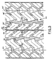
- the tread surface 80 of Figure 3 differs from that of Figure 1 primarily in that it includes a circumferentially-extending groove 90 at the mid-circumferential plane, the groove 90 separating the rows 88 and 88′ from one another laterally, and by the absence of a center rib or equivalent row of block.
- the various rubber blocks 34, 34′ and 36, 36′ are formed by the circumferential grooves 38, 38′ and 30, 30′, as well as by the groove segments 50, 50′, 52, 52′ extending between the circumferential grooves or between the grooves 38, 38′ and the respective tread lateral edges 24, 24′. Intersection of the groove walls for corner angles which are acute on the tread surface; the corner edges are chamfered as shown at 40, 42 and 44. In Figure 4, surface 40 is a chamfer that slopes toward the observer as it approaches the bottom of the groove 38.
- Figure 5 shows this same chamfer in sectional view at 42 and thus illustrates the true length of the chamfered surface as it goes to the bottom of groove 38.
- the chamfer surface 44 slopes to the bottom of a groove segment 50′ that connects the circumferential groove 38′ and the lateral edge of the tread 24′.
- the groove segment at such location has a portion that is of reduced depth, which accordingly accounts for the difference in length, slope, and shape of the chamfered surface.
- Rubber blocks 34, 34′ of rows 26, 26′ have circumferentially-spaced chamfers on their sides; there are two acute-angle corner chamfers on each block.
- rubber blocks 36, 36′ in rows 28, 28′ have four acute-angle corner chamfers which are spaced apart both laterally and circumferentially on the tread surface.
- the chamfers extend toward and preferably to the bottom of the grooves with which they are associated, as indicated in the drawings, and increase the stiffnesses of the rubber blocks with which they are associated, particularly in the circumferential direction. This is of importance in improving the uniformity of wear of the respective portions of the tread surface represented by the individual blocks. It also has been found to reduce the amplitudes of sound frequencies generated by the tire when in use.
- acute angles of groove-wall intersection are of greater concern with regard to both noise generation and irregular tread wear than are obtuse angles of intersection.
- the acute corner angles make the rubber blocks relatively flexible at the corner locations and also cause more force per unit area, or pressure, to be generated from their impact with the pavement. The flexibility allows scrubbing or scuffing of the rubber blocks in contact with the pavement, with a resultant tendency for nonuniform or irregular wear to occur.
- Variation of the sizes or slopes (configuration) of the chamfers of the rubber blocks may be used to vary the stiffnesses of the blocks to control tire wear characteristics and for the selective elimination of undesirable frequencies or amplitudes in the spectrum of sound generated by the tire in normal use.
- Configurations of the chamfers may be varied as a function of the pitch variations customarily used in the design and manufacture of pneumatic tires primarily for noise control.
Abstract
Description
- This invention relates to an all-season radial-ply pneumatic tire for passenger and light-truck vehicles as described for instance in US-A-4 619 300. An all-season pneumatic tire is regarded as one which currently qualifies for a mud and snow (M&S) rating under the criteria for such rating established by the Rubber Manufacturers Association, Akron, Ohio. In general, such rating requires that the tire tread have full-depth grooves that are angled laterally toward the respective lateral edges of the tread surface for at least one-half inch and such grooves are required to have a width of at least 0.060 inch.
- All-season tires are characterized by grooves that define blocks, and sometimes one or more ribs, in the tread surface. This results in a more aggressive appearance than that of a more conventional fully-ribbed tire and provides improved traction characteristics in snow and under wet conditions as compared to the conventional ribbed tire. All-season tires are distinguished from snow tires in that the former are required to satisfy all Federal Motor Vehicle Safety Standard 109 tests applicable to radial passenger tires in general, but the latter are not required to satisfy the provisions in such standards relating to high-speed test performance.
- All-season tires customarily employ block elements in their tread designs. The block elements are surrounded by grooves typically having a width at the tread surface of at least 2 mm, although the tread design may include some narrower grooves or "sipes" to improve traction or appearance characteristics of the tire. The net-to-gross ratio of the tread of such tires typically is in the range from about 55% to 70%. The net-to-gross ratio, for purposes of this specification, is defined as the ratio of the net road-contact area of the tread surface divided by the total area of the tread surface (road-contact area plus void area) for a tire under normal inflation pressure. The net-to-gross ratio is measured when the tire is normally loaded at an inflation pressure normal for such load.
- The use of blocks as elements in the tread of all-season tires tends to increase the noise level generated by such tires as compared to rib-type radial-ply pneumatic tires conventionally used in passenger and light-truck vehicle applications. Also, such blocks have a tendency toward irregular wear due primarily to their lack of stiffness in the circumferential direction of the tread. Such noise generation and irregular wear are accentuated at acute angles in the rubber blocks formed by intersections of groove walls.
- As the rubber blocks enter the area of contact of the tread surface of the tire with a paved road surface, the entering portion of the block compresses and then, as the block passes through the mid-region of the contact area, becomes elongated causing the block to scrub the pavement. This can result in irregular wear. On the other hand, noise generation occurs when edges of the blocks impact the pavement. Noise levels produced by all-season tires, as compared to rib-type tires, are generally greater and are caused in large part by the impacts of block edges with the paved road surface.
- An object of the invention is to overcome the aforementioned undesirable features of all-season radialply tires, while simultaneously maintaining their traction characteristics and improving their uniformity of wear and noise qualities.
- In accordance with the invention, as defined in the annexed claims an all-season radial-ply pneumatic tire for passenger and light-truck vehicles is disclosed.
- The claimed features improve the uniformity of wear of the rubber blocks by helping to prevent irregular wear from being initiated. Such wear, once initiated, tends to continue to occur throughout the life of the radial tire tread.
- The invention may be better understood by reference to the detailed description which follows and to the drawings.
-
- Figure 1 is a partial plan view of the tread of an all-season radial-ply pneumatic tire according to the invention;
- Figure 2 is a sectional view of the pneumatic tire. of Figure 1, the section being taken along the line 2-2 in Figure 1;
- Figure 3 is a partial plan view of a tire tread similar to that shown in Figure 1, but having a circumferential groove in the mid-circumferential plane rather than a rib;
- Figure 4 is a partial elevational view, taken in the direction 4-4 in Figure 1, illustrating a chamfer at the intersection of two walls of a rubber block in the tread shown in Figures 1 and 2;
- Figure 5 is a partial sectional elevational view taken along the line 5-5 in Figure 1 and illustrates the manner in which the chamfer of Figure 4 extends toward and to the bottom of a groove defining the rubber block; and
- Figure 6 is a partial sectional elevational view, in the direction 6-6 in Figure 1 and illustrates a chamfer extending toward and to the bottom of a groove segment of reduced depth as compared to the average depth of other groove segments surrounding one of the rubber blocks.
- In the drawings, symmetrically similar components on the right-hand side of the figures are given primed numerals corresponding to the components on the left-hand side.
- With particular reference now to Figures 1 and 2, there is shown a radial-ply pneumatic tire, generally designated by the
numeral 10, havingbeads carcass ply 14 extends within a rubber matrix.Carcass ply 14 has cords which are oriented in the radial direction of the tire. A belt structure is provided and is positioned radially outwardly of the carcass ply as viewed at themid-circumferential plane 22 of the tire. The belt structure includes at least one ply of cords that are oriented at both positive and negative angles with respect to the mid-circumferential plane. The positive and negative angles of the cords in the belt structure fall in the magnitude range from 17° to 30°. Preferably, the belt structure has at least twoplies ply 16 being oppositely oriented with regard to themid-circumferential plane 22 as compared to the parallel cords in thebelt ply 18. - The term "cord" as used herein is meant to include both textile and steel cord or cable.
- The
pneumatic tire 10 has an all-season tread design 20 most clearly illustrated in Figure 1 but with details of certain groove segments more clearly seen in Figure 2. - The
rubber tread 20 is positioned radially outwardly of the belt structure and has a surface that is adapted for use on paved road surfaces. The tread has grooves that are of width at the tread surface of at least 2 mm. All of the grooves hereinafter mentioned are to be considered to have widths equal to or greater than the minimum width of 2 mm. The tread width TW in Figure 2 is indicated by thelines - The
tread 20 includes two rows ofrubber blocks circumferential grooves groove segments groove segments tread 20 also includes third andfourth rows individual blocks respective rows groove segments fourth rows mid-circumferential plane 22 and are separated from one another by circumferentially-extendinggrooves grooves - The blocks 34, 34′ are identical to one another, except as to dimensional variations arising from normal circumferential pitching relationships commonly used in pneumatic tires to control tire noise. However, blocks 34′ could be made the mirror images of blocks 34, as could blocks 36 be made the mirror images of
blocks 36′. Were such changes to be made, the tread design would be converted from a non-directional tire to a tire that is directional in character, which in some cases provides traction or performance advantages not available in a non-directional design. - With particular reference now to Figure 3, the tread design generally designated by the
numeral 80 includes laterally opposed rows ofblock elements lateral edges Circumferential grooves blocks rows outer rows inner rows - The
tread surface 80 of Figure 3 differs from that of Figure 1 primarily in that it includes a circumferentially-extendinggroove 90 at the mid-circumferential plane, thegroove 90 separating therows - With particular reference now to Figures 1, 4, 5, and 6, it may be seen that the various rubber blocks 34, 34′ and 36, 36′ are formed by the
circumferential grooves groove segments grooves lateral edges surface 40 is a chamfer that slopes toward the observer as it approaches the bottom of thegroove 38. Figure 5 shows this same chamfer in sectional view at 42 and thus illustrates the true length of the chamfered surface as it goes to the bottom ofgroove 38. In Figure 6, thechamfer surface 44 slopes to the bottom of agroove segment 50′ that connects thecircumferential groove 38′ and the lateral edge of thetread 24′. The groove segment at such location has a portion that is of reduced depth, which accordingly accounts for the difference in length, slope, and shape of the chamfered surface. - Rubber blocks 34, 34′ of
rows rows - The chamfers extend toward and preferably to the bottom of the grooves with which they are associated, as indicated in the drawings, and increase the stiffnesses of the rubber blocks with which they are associated, particularly in the circumferential direction. This is of importance in improving the uniformity of wear of the respective portions of the tread surface represented by the individual blocks. It also has been found to reduce the amplitudes of sound frequencies generated by the tire when in use. In the rubber tread blocks, acute angles of groove-wall intersection are of greater concern with regard to both noise generation and irregular tread wear than are obtuse angles of intersection. The acute corner angles make the rubber blocks relatively flexible at the corner locations and also cause more force per unit area, or pressure, to be generated from their impact with the pavement. The flexibility allows scrubbing or scuffing of the rubber blocks in contact with the pavement, with a resultant tendency for nonuniform or irregular wear to occur.
- Variation of the sizes or slopes (configuration) of the chamfers of the rubber blocks may be used to vary the stiffnesses of the blocks to control tire wear characteristics and for the selective elimination of undesirable frequencies or amplitudes in the spectrum of sound generated by the tire in normal use. Configurations of the chamfers may be varied as a function of the pitch variations customarily used in the design and manufacture of pneumatic tires primarily for noise control.
- Based upon the foregoing description of the invention, what is claimed is:
Claims (3)
a radial carcass ply (14);
a belt structure positioned radially outwardly of the carcass ply, the belt structure including at least one ply (16, 18) of cords, the belt structure having cords oriented at both positive and negative angles, in the magnitude range from 17° to 30°, with respect to the mid-circumferential plane (22) of the tire; and
a rubber tread (20) positioned radially outwardly of the belt structure and having a surface adapted for use on paved road surfaces, the tread having circumferentially extending grooves (38,38′; 30,30′) and groove segments (50,50′;52,52′) that connect the circumferentially grooves (38,38′;30,30′) or the circumferentially extending grooves (38,38′) and the lateral edges (24,24′) of the tread, the groove and groove segments have a width at the tread surface of at least 2 mm and the net-to-gross ratio of the tread being greater than 55%, such grooves and groove segments defining blocks (34,34′; 36,36′) of rubber surrounded either fully by such grooves and groove segments or by such grooves, groove segments and the lateral edges of the tread road-contact surface, the rubber blocks being spaced apart circumferentially around the tread; the tire and its tread being characterized by corner angles which are acute on the tread surface formed by the intersections of the walls of the grooves (38,38′; 30,30′) with the groove segments (50,50′;52,52′), the corner edges being chamfered (40, 42, 44) and extending to the bottoms of the respective grooves.
Priority Applications (1)
| Application Number | Priority Date | Filing Date | Title |
|---|---|---|---|
| AT87630015T ATE74072T1 (en) | 1986-01-29 | 1987-01-23 | ALL SEASON PNEUMATIC TIRES WITH REMOVED BLOCKS. |
Applications Claiming Priority (2)
| Application Number | Priority Date | Filing Date | Title |
|---|---|---|---|
| US06/823,696 US4690189A (en) | 1986-01-29 | 1986-01-29 | All-season pneumatic tire with chamfered tread blocks |
| US823696 | 1986-01-29 |
Publications (3)
| Publication Number | Publication Date |
|---|---|
| EP0233135A2 EP0233135A2 (en) | 1987-08-19 |
| EP0233135A3 EP0233135A3 (en) | 1988-08-24 |
| EP0233135B1 true EP0233135B1 (en) | 1992-03-25 |
Family
ID=25239445
Family Applications (1)
| Application Number | Title | Priority Date | Filing Date |
|---|---|---|---|
| EP87630015A Expired - Lifetime EP0233135B1 (en) | 1986-01-29 | 1987-01-23 | All-season pneumatic tire with chamfered tread blocks |
Country Status (8)
| Country | Link |
|---|---|
| US (1) | US4690189A (en) |
| EP (1) | EP0233135B1 (en) |
| JP (2) | JPS62181904A (en) |
| KR (1) | KR870007023A (en) |
| AT (1) | ATE74072T1 (en) |
| AU (1) | AU576106B2 (en) |
| CA (1) | CA1251122A (en) |
| DE (1) | DE3777671D1 (en) |
Families Citing this family (63)
| Publication number | Priority date | Publication date | Assignee | Title |
|---|---|---|---|---|
| JPS62255203A (en) * | 1986-04-30 | 1987-11-07 | Bridgestone Corp | Pneumatic radial tire |
| IT1222420B (en) * | 1986-08-05 | 1990-09-05 | Uniroyal Englebert Gmbh | TIRE CARVING OF MOTOR VEHICLE TIRES |
| US4807679A (en) * | 1987-06-11 | 1989-02-28 | The Goodyear Tire & Rubber Company | Pneumatic tire tread having sipes |
| US4856571A (en) * | 1987-06-11 | 1989-08-15 | The Goodyear Tire & Rubber Company | Pneumatic tire |
| US5176765A (en) * | 1988-04-13 | 1993-01-05 | Bridgestone Corporation | Pneumatic tire having outer tread layer of foam rubber |
| JPH0220407A (en) * | 1988-07-09 | 1990-01-24 | Sumitomo Rubber Ind Ltd | Radial tire for heavy duty vehicle |
| JP3061276B2 (en) * | 1988-07-29 | 2000-07-10 | 住友ゴム工業株式会社 | Pneumatic tire |
| DE68926578T2 (en) * | 1988-11-30 | 1996-10-02 | Sumitomo Rubber Ind | Radial pneumatic tire |
| JPH02216304A (en) * | 1989-02-17 | 1990-08-29 | Sumitomo Rubber Ind Ltd | Tire for snow/ice covered road |
| GB8907400D0 (en) * | 1989-04-01 | 1989-05-17 | Sumitomo Rubber Ind | Tyre thread pattern |
| AT394337B (en) * | 1989-04-13 | 1992-03-10 | Semperit Ag | RADIAL TIRES FOR TRUCKS |
| JPH02270609A (en) * | 1989-04-13 | 1990-11-05 | Yokohama Rubber Co Ltd:The | Pneumatic tire |
| US5361814A (en) * | 1989-11-15 | 1994-11-08 | The Goodyear Tire & Rubber Company | Asymmetric tire |
| DE4107051A1 (en) * | 1991-03-06 | 1992-09-10 | Uniroyal Englebert Gmbh | Low noise tyre tread profile - has series of blocks of different sizes separated by grooves of different depths, some of which are also e.g. stepped |
| JPH066005U (en) * | 1992-07-02 | 1994-01-25 | 株式会社ブリヂストン | Motorcycle tires |
| JP2968664B2 (en) * | 1992-08-17 | 1999-10-25 | 住友ゴム工業株式会社 | Heavy duty tire |
| US5361815A (en) * | 1992-11-16 | 1994-11-08 | The Goodyear Tire & Rubber Company | Tread for a tire with blocks and ribs |
| DE4306483C2 (en) * | 1993-03-02 | 2000-05-04 | Pirelli Reifenwerke | Tread pattern for winter tires |
| US5363895A (en) * | 1993-06-23 | 1994-11-15 | The Goodyear Tire & Rubber Company | Bias ply pneumatic tire |
| JP2892924B2 (en) * | 1993-11-30 | 1999-05-17 | 住友ゴム工業株式会社 | Low noise tire |
| AT404338B (en) * | 1994-11-24 | 1998-10-27 | Semperit Ag | VEHICLE TIRES |
| US5538060A (en) * | 1994-12-27 | 1996-07-23 | The Goodyear Tire & Rubber Company | Pneumatic tire having tread portion including blocks |
| US5833779A (en) * | 1995-12-12 | 1998-11-10 | The Goodyear Tire & Rubber Company | Winter automobile or light truck tire including sipes |
| US5798124A (en) * | 1996-01-17 | 1998-08-25 | The Goodyear Tire & Rubber Company | Tire tread element mold chamfer to modify RCF and/or RSAT using the existing mold |
| JPH10175405A (en) * | 1996-12-19 | 1998-06-30 | Sumitomo Rubber Ind Ltd | Radial tire for heavy load |
| EP0924110B1 (en) | 1996-12-27 | 2004-12-08 | Bridgestone Corporation | Pneumatic tire designing method |
| IT1289182B1 (en) * | 1997-01-20 | 1998-09-29 | Pirelli | TIRE WITH LOW ROLLING RESISTANCE IN PARTICULAR FOR DRIVE WHEELS OF HEAVY VEHICLES |
| US6213180B1 (en) * | 1997-03-26 | 2001-04-10 | Bridgestone Corporation | Pneumatic radial tire including beveled acute angle corner portions |
| JP3771351B2 (en) | 1997-05-02 | 2006-04-26 | 株式会社ブリヂストン | Pneumatic tire |
| JPH1148719A (en) | 1997-08-07 | 1999-02-23 | Bridgestone Corp | Pneumatic tire for heavy load |
| JP3869102B2 (en) * | 1997-12-25 | 2007-01-17 | 株式会社ブリヂストン | Pneumatic tire |
| JP3958426B2 (en) * | 1998-01-14 | 2007-08-15 | 株式会社ブリヂストン | Pneumatic radial tire for passenger cars with directional inclined grooves |
| US6021830A (en) * | 1998-02-06 | 2000-02-08 | Sumitomo Rubber Industries, Ltd. | Pneumatic tire including fine groove |
| US6823911B1 (en) * | 1999-02-26 | 2004-11-30 | Bridgestone Corporation | Pneumatic tire including pseudo-land portion formed in circumferential groove |
| JP4275283B2 (en) * | 2000-02-16 | 2009-06-10 | 株式会社ブリヂストン | Pneumatic tire |
| JP4518641B2 (en) * | 2000-07-18 | 2010-08-04 | 株式会社ブリヂストン | Pneumatic tire |
| US6520230B1 (en) * | 2000-09-06 | 2003-02-18 | The Goodyear Tire & Rubber Company | Tire with an open tread |
| JP4562268B2 (en) * | 2000-10-10 | 2010-10-13 | 株式会社ブリヂストン | Pneumatic tire |
| US6983777B2 (en) * | 2002-10-15 | 2006-01-10 | The Goodyear Tire & Rubber Company | Tire tread with multi-planar chamfers |
| JP4545565B2 (en) * | 2004-11-25 | 2010-09-15 | 東洋ゴム工業株式会社 | Pneumatic tire |
| JP4776523B2 (en) * | 2006-12-20 | 2011-09-21 | 株式会社ブリヂストン | Pneumatic tire |
| CN101588934B (en) * | 2006-12-20 | 2011-06-29 | 株式会社普利司通 | Pneumatic tire |
| US8261790B2 (en) | 2008-08-18 | 2012-09-11 | The Goodyear Tire & Rubber Company | Directional tread for a tire |
| EP2347918B1 (en) * | 2008-10-21 | 2015-05-27 | Bridgestone Corporation | Tire |
| JP5123981B2 (en) * | 2010-04-27 | 2013-01-23 | 住友ゴム工業株式会社 | Heavy duty tire |
| JP5144720B2 (en) * | 2010-06-17 | 2013-02-13 | 住友ゴム工業株式会社 | Pneumatic tire |
| JP5266307B2 (en) * | 2010-12-27 | 2013-08-21 | 住友ゴム工業株式会社 | Pneumatic tire |
| JP5062344B1 (en) * | 2011-04-12 | 2012-10-31 | 横浜ゴム株式会社 | Pneumatic tire |
| JP5337201B2 (en) * | 2011-06-20 | 2013-11-06 | 住友ゴム工業株式会社 | Pneumatic tire |
| JP5727965B2 (en) * | 2012-05-02 | 2015-06-03 | 住友ゴム工業株式会社 | Pneumatic tire |
| JP6330568B2 (en) * | 2014-08-11 | 2018-05-30 | 横浜ゴム株式会社 | Pneumatic tire |
| JP6082378B2 (en) * | 2014-11-28 | 2017-02-15 | 住友ゴム工業株式会社 | Pneumatic tire |
| CN113462318A (en) | 2015-05-21 | 2021-10-01 | 巴斯夫欧洲公司 | Stabilization of hot melt adhesives |
| EP3176006B1 (en) * | 2015-11-24 | 2018-06-20 | Sumitomo Rubber Industries Limited | Tire |
| JP2017114384A (en) * | 2015-12-25 | 2017-06-29 | 東洋ゴム工業株式会社 | Pneumatic tire |
| US10279633B2 (en) | 2016-12-12 | 2019-05-07 | The Goodyear Tire & Rubber Company | Tread for a snow tire |
| JP6332481B1 (en) * | 2017-01-11 | 2018-05-30 | 横浜ゴム株式会社 | Pneumatic tire |
| JP6822195B2 (en) * | 2017-02-15 | 2021-01-27 | 横浜ゴム株式会社 | Pneumatic tires |
| JP6828496B2 (en) * | 2017-02-17 | 2021-02-10 | 横浜ゴム株式会社 | Pneumatic tires |
| MX2019014663A (en) * | 2017-06-12 | 2020-02-07 | Pirelli | Tyre for vehicle wheels. |
| JP6604390B2 (en) * | 2018-01-16 | 2019-11-13 | 横浜ゴム株式会社 | Pneumatic tire |
| JP7098962B2 (en) * | 2018-03-05 | 2022-07-12 | 住友ゴム工業株式会社 | tire |
| WO2023242787A1 (en) * | 2022-06-16 | 2023-12-21 | Pirelli Tyre S.P.A. | Tyre for vehicle wheels |
Citations (1)
| Publication number | Priority date | Publication date | Assignee | Title |
|---|---|---|---|---|
| US4619300A (en) * | 1983-11-30 | 1986-10-28 | Bridgestone Corporation | Pneumatic tire tread |
Family Cites Families (15)
| Publication number | Priority date | Publication date | Assignee | Title |
|---|---|---|---|---|
| US2505137A (en) * | 1949-02-23 | 1950-04-25 | Lee Rubber & Tire Corp | Vehicle tire |
| US2779378A (en) * | 1953-11-30 | 1957-01-29 | Firestone Tire & Rubber Co | Tire tread construction |
| US3055410A (en) * | 1960-01-29 | 1962-09-25 | Atlas Supply Company | Tires |
| JPS5759102B2 (en) * | 1974-03-15 | 1982-12-13 | Tokyo Shibaura Electric Co | |
| FR2312385A1 (en) * | 1975-05-30 | 1976-12-24 | Uniroyal | TREAD STRUCTURE AND PNEUMATIC BANDAGE WRAP WITH APPLICATION |
| JPS52115001A (en) * | 1976-03-24 | 1977-09-27 | Bridgestone Corp | Pneumatic radial tire for heavy load |
| JPS5330503A (en) * | 1976-08-31 | 1978-03-22 | Bridgestone Corp | Tread coating of large-sized pneumatic radial tire |
| JPS5342921A (en) * | 1976-09-28 | 1978-04-18 | Siemens Ag | Typewriter |
| JPS54140604A (en) * | 1978-04-20 | 1979-11-01 | Dayco Corp | Printing blanket restorable from pressural deformation |
| JPS55147901A (en) * | 1979-05-07 | 1980-11-18 | Toyo Electric Mfg Co Ltd | Mounting method of reactor for chopper of electric motor vehicle |
| US4456046A (en) * | 1981-05-11 | 1984-06-26 | Miller Timothy I | High-speed tires |
| JPS5818249A (en) * | 1981-07-27 | 1983-02-02 | アルプス電気株式会社 | Anisotropic conductive elastomer sheet and its manufacture |
| JPS5940902A (en) * | 1982-08-31 | 1984-03-06 | Yokohama Rubber Co Ltd:The | Pneumatic tire |
| JPS59179408A (en) * | 1983-03-31 | 1984-10-12 | Yokohama Rubber Co Ltd:The | Pneumatic tire |
| JPS6015204A (en) * | 1983-07-08 | 1985-01-25 | Yokohama Rubber Co Ltd:The | Flat tire for travelling at high speed |
-
1986
- 1986-01-29 US US06/823,696 patent/US4690189A/en not_active Expired - Lifetime
-
1987
- 1987-01-13 CA CA000527217A patent/CA1251122A/en not_active Expired
- 1987-01-23 EP EP87630015A patent/EP0233135B1/en not_active Expired - Lifetime
- 1987-01-23 DE DE8787630015T patent/DE3777671D1/en not_active Expired - Fee Related
- 1987-01-23 AT AT87630015T patent/ATE74072T1/en not_active IP Right Cessation
- 1987-01-28 KR KR870000676A patent/KR870007023A/en not_active Application Discontinuation
- 1987-01-28 JP JP62016332A patent/JPS62181904A/en active Pending
- 1987-01-28 AU AU68047/87A patent/AU576106B2/en not_active Ceased
-
1993
- 1993-02-16 JP JP004754U patent/JPH0571004U/en active Pending
Patent Citations (1)
| Publication number | Priority date | Publication date | Assignee | Title |
|---|---|---|---|---|
| US4619300A (en) * | 1983-11-30 | 1986-10-28 | Bridgestone Corporation | Pneumatic tire tread |
Also Published As
| Publication number | Publication date |
|---|---|
| JPH0571004U (en) | 1993-09-24 |
| AU576106B2 (en) | 1988-08-11 |
| DE3777671D1 (en) | 1992-04-30 |
| KR870007023A (en) | 1987-08-14 |
| ATE74072T1 (en) | 1992-04-15 |
| EP0233135A3 (en) | 1988-08-24 |
| EP0233135A2 (en) | 1987-08-19 |
| JPS62181904A (en) | 1987-08-10 |
| US4690189A (en) | 1987-09-01 |
| CA1251122A (en) | 1989-03-14 |
| AU6804787A (en) | 1987-07-30 |
Similar Documents
| Publication | Publication Date | Title |
|---|---|---|
| EP0233135B1 (en) | All-season pneumatic tire with chamfered tread blocks | |
| EP0485883B1 (en) | Winter type tire tread | |
| US5896905A (en) | Tread for heavy-vehicle tire in which the central ribs are provided with inclined incisions | |
| EP1189770B1 (en) | High-performance tyre for a motor vehicle | |
| US4724878A (en) | Heavy-duty pneumatic radial tire tread with narrow groove near shoulder | |
| US6439284B1 (en) | Tread for a pneumatic tire including aquachannel | |
| EP1036029B1 (en) | Tire having sacrificial bridging | |
| GB2118910A (en) | Tyre tread | |
| EP0904960A2 (en) | Studless tyre | |
| JPH0234802B2 (en) | ||
| KR100612401B1 (en) | Tyre and tread thereof | |
| JPH05319029A (en) | Pneumatic radial tire for heavy load | |
| US4977942A (en) | Pneumatic tire having defined lug groove configuration | |
| JPH11321237A (en) | Pneumatic radial tire | |
| EP0235072A2 (en) | All-season pneumatic tire with improved tread stiffness | |
| EP0710577A1 (en) | Pneumatic radial tire | |
| CA2145786A1 (en) | Tread for pneumatic tire and tire comprising such a tread | |
| EP0812708B1 (en) | Pneumatic radial tires | |
| EP0282252A2 (en) | Radial tyre | |
| JP4979864B2 (en) | High performance tire for automobile | |
| CA1334373C (en) | Radial tire for heavy duty vehicles | |
| JPH05178015A (en) | Pneumatic radial tire for heavy load | |
| US11571934B2 (en) | Tire | |
| JPH0834205A (en) | Pneumatic tire | |
| JPH08192607A (en) | Pneumatic tire for heavy load |
Legal Events
| Date | Code | Title | Description |
|---|---|---|---|
| PUAI | Public reference made under article 153(3) epc to a published international application that has entered the european phase |
Free format text: ORIGINAL CODE: 0009012 |
|
| 17P | Request for examination filed |
Effective date: 19870207 |
|
| AK | Designated contracting states |
Kind code of ref document: A2 Designated state(s): AT BE DE FR GB LU NL SE |
|
| PUAL | Search report despatched |
Free format text: ORIGINAL CODE: 0009013 |
|
| AK | Designated contracting states |
Kind code of ref document: A3 Designated state(s): AT BE DE FR GB LU NL SE |
|
| 17Q | First examination report despatched |
Effective date: 19900731 |
|
| GRAA | (expected) grant |
Free format text: ORIGINAL CODE: 0009210 |
|
| AK | Designated contracting states |
Kind code of ref document: B1 Designated state(s): AT BE DE FR GB LU NL SE |
|
| REF | Corresponds to: |
Ref document number: 74072 Country of ref document: AT Date of ref document: 19920415 Kind code of ref document: T |
|
| REF | Corresponds to: |
Ref document number: 3777671 Country of ref document: DE Date of ref document: 19920430 |
|
| ET | Fr: translation filed | ||
| PLBI | Opposition filed |
Free format text: ORIGINAL CODE: 0009260 |
|
| 26 | Opposition filed |
Opponent name: SEMPERIT REIFEN AKTIENGESELLSCHAFT Effective date: 19921222 |
|
| NLR1 | Nl: opposition has been filed with the epo |
Opponent name: SEMPERIT REIFEN AKTIENGESELLSCHAFT |
|
| EPTA | Lu: last paid annual fee | ||
| PLBN | Opposition rejected |
Free format text: ORIGINAL CODE: 0009273 |
|
| STAA | Information on the status of an ep patent application or granted ep patent |
Free format text: STATUS: OPPOSITION REJECTED |
|
| 27O | Opposition rejected |
Effective date: 19940310 |
|
| NLR2 | Nl: decision of opposition | ||
| EAL | Se: european patent in force in sweden |
Ref document number: 87630015.3 |
|
| PGFP | Annual fee paid to national office [announced via postgrant information from national office to epo] |
Ref country code: LU Payment date: 19960201 Year of fee payment: 10 |
|
| PG25 | Lapsed in a contracting state [announced via postgrant information from national office to epo] |
Ref country code: LU Free format text: LAPSE BECAUSE OF NON-PAYMENT OF DUE FEES Effective date: 19970123 |
|
| PGFP | Annual fee paid to national office [announced via postgrant information from national office to epo] |
Ref country code: AT Payment date: 20001212 Year of fee payment: 15 |
|
| PGFP | Annual fee paid to national office [announced via postgrant information from national office to epo] |
Ref country code: NL Payment date: 20001222 Year of fee payment: 15 |
|
| PGFP | Annual fee paid to national office [announced via postgrant information from national office to epo] |
Ref country code: SE Payment date: 20010103 Year of fee payment: 15 Ref country code: FR Payment date: 20010103 Year of fee payment: 15 |
|
| PGFP | Annual fee paid to national office [announced via postgrant information from national office to epo] |
Ref country code: DE Payment date: 20010126 Year of fee payment: 15 |
|
| PGFP | Annual fee paid to national office [announced via postgrant information from national office to epo] |
Ref country code: BE Payment date: 20010326 Year of fee payment: 15 |
|
| REG | Reference to a national code |
Ref country code: GB Ref legal event code: IF02 |
|
| PG25 | Lapsed in a contracting state [announced via postgrant information from national office to epo] |
Ref country code: AT Free format text: LAPSE BECAUSE OF NON-PAYMENT OF DUE FEES Effective date: 20020123 |
|
| PG25 | Lapsed in a contracting state [announced via postgrant information from national office to epo] |
Ref country code: SE Free format text: LAPSE BECAUSE OF NON-PAYMENT OF DUE FEES Effective date: 20020124 |
|
| PG25 | Lapsed in a contracting state [announced via postgrant information from national office to epo] |
Ref country code: BE Free format text: LAPSE BECAUSE OF NON-PAYMENT OF DUE FEES Effective date: 20020131 |
|
| BERE | Be: lapsed |
Owner name: THE GOODYEAR TIRE & RUBBER CY Effective date: 20020131 |
|
| PG25 | Lapsed in a contracting state [announced via postgrant information from national office to epo] |
Ref country code: NL Free format text: LAPSE BECAUSE OF NON-PAYMENT OF DUE FEES Effective date: 20020801 Ref country code: DE Free format text: LAPSE BECAUSE OF NON-PAYMENT OF DUE FEES Effective date: 20020801 |
|
| EUG | Se: european patent has lapsed |
Ref document number: 87630015.3 |
|
| PG25 | Lapsed in a contracting state [announced via postgrant information from national office to epo] |
Ref country code: FR Free format text: LAPSE BECAUSE OF NON-PAYMENT OF DUE FEES Effective date: 20020930 |
|
| NLV4 | Nl: lapsed or anulled due to non-payment of the annual fee |
Effective date: 20020801 |
|
| REG | Reference to a national code |
Ref country code: FR Ref legal event code: ST |
|
| PGFP | Annual fee paid to national office [announced via postgrant information from national office to epo] |
Ref country code: GB Payment date: 20041210 Year of fee payment: 19 |
|
| PG25 | Lapsed in a contracting state [announced via postgrant information from national office to epo] |
Ref country code: GB Free format text: LAPSE BECAUSE OF NON-PAYMENT OF DUE FEES Effective date: 20060123 |
|
| GBPC | Gb: european patent ceased through non-payment of renewal fee |
Effective date: 20060123 |