EP0413113A2 - Electronically commutated motor for vacuum cleaner and the like - Google Patents
Electronically commutated motor for vacuum cleaner and the like Download PDFInfo
- Publication number
- EP0413113A2 EP0413113A2 EP90112010A EP90112010A EP0413113A2 EP 0413113 A2 EP0413113 A2 EP 0413113A2 EP 90112010 A EP90112010 A EP 90112010A EP 90112010 A EP90112010 A EP 90112010A EP 0413113 A2 EP0413113 A2 EP 0413113A2
- Authority
- EP
- European Patent Office
- Prior art keywords
- rotor
- turbine
- stator
- permanent magnets
- motor
- Prior art date
- Legal status (The legal status is an assumption and is not a legal conclusion. Google has not performed a legal analysis and makes no representation as to the accuracy of the status listed.)
- Granted
Links
Images


Classifications
-
- H—ELECTRICITY
- H02—GENERATION; CONVERSION OR DISTRIBUTION OF ELECTRIC POWER
- H02K—DYNAMO-ELECTRIC MACHINES
- H02K9/00—Arrangements for cooling or ventilating
-
- A—HUMAN NECESSITIES
- A47—FURNITURE; DOMESTIC ARTICLES OR APPLIANCES; COFFEE MILLS; SPICE MILLS; SUCTION CLEANERS IN GENERAL
- A47L—DOMESTIC WASHING OR CLEANING; SUCTION CLEANERS IN GENERAL
- A47L5/00—Structural features of suction cleaners
- A47L5/12—Structural features of suction cleaners with power-driven air-pumps or air-compressors, e.g. driven by motor vehicle engine vacuum
- A47L5/22—Structural features of suction cleaners with power-driven air-pumps or air-compressors, e.g. driven by motor vehicle engine vacuum with rotary fans
-
- H—ELECTRICITY
- H02—GENERATION; CONVERSION OR DISTRIBUTION OF ELECTRIC POWER
- H02K—DYNAMO-ELECTRIC MACHINES
- H02K1/00—Details of the magnetic circuit
- H02K1/06—Details of the magnetic circuit characterised by the shape, form or construction
- H02K1/22—Rotating parts of the magnetic circuit
- H02K1/27—Rotor cores with permanent magnets
- H02K1/2706—Inner rotors
- H02K1/272—Inner rotors the magnetisation axis of the magnets being perpendicular to the rotor axis
- H02K1/274—Inner rotors the magnetisation axis of the magnets being perpendicular to the rotor axis the rotor consisting of two or more circumferentially positioned magnets
- H02K1/2753—Inner rotors the magnetisation axis of the magnets being perpendicular to the rotor axis the rotor consisting of two or more circumferentially positioned magnets the rotor consisting of magnets or groups of magnets arranged with alternating polarity
- H02K1/278—Surface mounted magnets; Inset magnets
-
- H—ELECTRICITY
- H02—GENERATION; CONVERSION OR DISTRIBUTION OF ELECTRIC POWER
- H02K—DYNAMO-ELECTRIC MACHINES
- H02K29/00—Motors or generators having non-mechanical commutating devices, e.g. discharge tubes or semiconductor devices
- H02K29/06—Motors or generators having non-mechanical commutating devices, e.g. discharge tubes or semiconductor devices with position sensing devices
- H02K29/08—Motors or generators having non-mechanical commutating devices, e.g. discharge tubes or semiconductor devices with position sensing devices using magnetic effect devices, e.g. Hall-plates, magneto-resistors
-
- H—ELECTRICITY
- H02—GENERATION; CONVERSION OR DISTRIBUTION OF ELECTRIC POWER
- H02K—DYNAMO-ELECTRIC MACHINES
- H02K9/00—Arrangements for cooling or ventilating
- H02K9/02—Arrangements for cooling or ventilating by ambient air flowing through the machine
- H02K9/04—Arrangements for cooling or ventilating by ambient air flowing through the machine having means for generating a flow of cooling medium
- H02K9/06—Arrangements for cooling or ventilating by ambient air flowing through the machine having means for generating a flow of cooling medium with fans or impellers driven by the machine shaft
Abstract
Description
Die Erfindung betrifft einen elektronisch kommutierten Motor für Staubsauger oder dergleichen mit einem Stator mit Erregerwicklungen und mit in einem Luftspalt drehend angeordneten Rotor, welcher paketiert Rotorbleche und entsprechend der Polzahl des Stators am Umfang Permagnentmagnete aufweist und weiterhin auf der Rotorwelle ein Lüfterrad als Ventilator vorgesehen ist und die Rotorwelle mit einer Turbine zur Erzeugung eines Ansaugluftstromes in Verbindung steht.The invention relates to an electronically commutated motor for vacuum cleaners or the like with a stator with excitation windings and with a rotor rotatingly arranged in an air gap, which packets rotor laminations and, according to the number of poles of the stator on the circumference, has permanent magnets and furthermore a fan wheel is provided as a fan on the rotor shaft and the rotor shaft is connected to a turbine for generating an intake air flow.
Bei elektrischen Antrieben, insbesondere aber bei Staub- und Schmutzsauger oder dergleichen, sind bereits kommutierte bzw. bürstenlose Motoren bekannt, die mit hoher Leistung arbeiten, nachteilig aber insbesondere in hohen Drehzahlbereichen nicht die notwendige Betriebssicherheit aufweisen. Die bisher bekannten Motoren haben zwar ein hohes Anlaufmoment, weisen aber nachteilig ein relativ ungünstiges Leistungsvolumenverhältnis auf und benötigen viel Platz, insbesondere in Geräten, die manuell handhabbar ausgebildet sind.In the case of electric drives, but particularly in the case of vacuum cleaners and dirt collectors or the like, commutated or brushless motors are already known which work with high power, but disadvantageously, especially in high speed ranges, do not have the necessary operational reliability. The previously known motors have a high starting torque, but disadvantageously have a relatively unfavorable power / volume ratio and require a lot of space, in particular in devices which are designed to be handled manually.
Die bisher bekannten Motoren weisen weiterhin den Nachteil auf, daß in Verbindung mit der großen Motorleistung und der dadurch freigesetzten Wärme die Ausgestaltung der Lagerung des Motors, insbesondere wenn zusätzlich eine Turbine angetrieben werden soll und genügend ausgebildet ist, so daß Gefahr besteht, daß der Motor bzw. die Lagerung heiß läuft, insbesondere hinsichtlich der bisher bekannten, ungenügenden Führung der Kühlluft für den Motor und der Lagerung der angetriebenen Turbine.The previously known engines also have the disadvantage that, in conjunction with the large engine power and the heat released thereby, the design of the mounting of the engine, in particular if a turbine is also to be driven and is sufficiently designed so that there is a risk that the engine or the storage runs hot, especially with regard to the previously known, insufficient guidance of the cooling air for the engine and the storage of the driven turbine.
Aufgabe der vorliegenden Erfindung ist es deshalb, einen elektronisch kommutierten Motor so auszugestalten, daß ohne Berücksichtigung des Anlaufmomentes bei hohen Leistungen eine erhöhte Drehzahl erreicht wird bei insbesondere betriebssicherer Ausgestaltung des Motors und der Turbine, ohne daß Gefahr besteht, daß der Motor, die Motorlagerung oder die Turbinenlagerung heiß läuft.The object of the present invention is therefore to design an electronically commutated motor so that without taking into account the Starting torque at high power an increased speed is achieved with a particularly reliable design of the engine and the turbine, without there being a risk that the engine, the engine mount or the turbine mount runs hot.
Zur Lösung der Aufgabe ist es gemäß der Erfindung vorgesehen, daß das Lüfterrad auf der Rotorwelle dem Motor in Ansaugrichtung der Kühlluft nachgeschaltet ist und das Lüfterrad hierbei in unmittelbarer Nähe des Turbinenläufers im oberen Lagerschild der Turbine angeordnet ist.To achieve the object, it is provided according to the invention that the fan wheel on the rotor shaft is connected downstream of the motor in the suction direction of the cooling air and the fan wheel is arranged in the immediate vicinity of the turbine rotor in the upper end shield of the turbine.
Das Wesen der Erfindung liegt darin, daß das Lüfterrad des Motors, welches am Ventilator liegt, unmittelbar in der Nähe der hochbeanspruchten Turbinenlagerung angeordnet ist, so daß die Kühlluft für den Motor gleichzeitig auch unmittelbar die Turbinenlagerung erreicht, insbesondere über das obere Lagerschild, so daß bei hoher Betriebssicherheit ein Heißlaufen des Motors bzw. der Lagerung des Motors und der Turbine vermieden wird.The essence of the invention is that the fan wheel of the motor, which is located on the fan, is arranged in the immediate vicinity of the highly stressed turbine bearing, so that the cooling air for the motor also reaches the turbine bearing directly, in particular via the upper end shield, so that in the event of high operational safety, overheating of the engine or the engine and turbine bearings are avoided.
Durch die Nachschaltung des Lüfterrades an dem Motor in Ansaugrichtung der Kühlluft durchläuft die Kühlluft zunächst den Motor selbst und kühlt dann nach dem Durchlaufen des Motors noch die obere Motorenlagerung bzw. die unmittelbar daran angrenzende Lagerung des Turbinenläufers, wodurch eine hohe Betriebssicherheit erreicht wird.By connecting the fan wheel on the motor in the direction of suction of the cooling air, the cooling air first passes through the motor itself and then cools the upper motor mounting or the immediately adjacent bearing of the turbine runner after passing through the motor, thereby achieving high operational reliability.
In vorteilhafter Ausgestaltung ist es vorgesehen, daß das obere Lagerschild der Turbine zwischen dem Lüfterrad und dem Turbinenläufer nach Art einer Zwischenwand einstückig ausgebildet ist und ausgehend von der Lagerung der Rotorwelle in Richtung zum Lüfterrad Ausnehmungen und Ausformungen aufweist, derart, daß von dem Lagerschild der Turbine gleichzeitig die Auslaßschlitze des Lüfterrades für Kühlluft und die Auslaßöffnungen für die Abluft der Turbine ausgehen.In an advantageous embodiment, it is provided that the upper bearing plate of the turbine between the fan wheel and the turbine rotor is formed in one piece in the manner of an intermediate wall and, starting from the bearing of the rotor shaft in the direction of the fan wheel, has recesses and shapes such that the bearing plate of the turbine at the same time, the outlet slots of the fan wheel for cooling air and the outlet openings for the exhaust air from the turbine go out.
Von einem einzigen Lagerschild gehen demnach in Verbindung mit Ausnehmungen und Ausformungen gleichzeitig Auslaßschlitze für Kühlluft und Auslaßöffnungen für die Abluft der Turbine aus, so daß hierbei zunächst das Lagerschild selbst , aber insbesondere die Lagerungen im Bereich des Lagerschildes vorteilhaft gekühlt werden, hier insbesondere die obere Motorenlagerung und die Lagerung des Turbinenläufers.Accordingly, outlet slots for cooling air and outlet openings for the exhaust air of the turbine emanate from a single end shield in connection with recesses and formations, so that initially the end shield itself, but in particular the bearings in the region of the end shield, are advantageously cooled, here in particular the upper engine mounting and the bearing of the turbine runner.
Die Auslaßschlitze für Kühlluft und die Auslaßöffnungen für die Abluft der Turbine sind hierbei in Verbindung mit dem einstückig ausgebildeten Lagerschild benachbart angeordnet, so daß in einem engen Bereich der Motorturbinenanordnung ein einheitliches Ausströmen erfolgt, nämlich das Ausströmen der Kühlluft aus den Auslaßschlitzen und das Ausströmen der Abluft der Turbine aus den Auslaßöffnungen, wodurch in sich gegenseitig erhöhender Abführwirkung der Luftströme, weil die Abluft der Turbine gleichzeitig auch Abluft des Lüfterrades wegführt und umgekehrt, eine hohe Kühlleistung von Motor und Lagerung geschaffen wird bei hoher Betriebssicherheit.The outlet slots for cooling air and the outlet openings for the exhaust air of the turbine are in this case arranged in connection with the integrally formed bearing plate, so that there is a uniform outflow in a narrow area of the engine turbine arrangement, namely the outflow of the cooling air from the outlet slots and the outflow of the exhaust air the turbine from the outlet openings, resulting in a mutually increasing laxative effect of the air currents, because the exhaust air from the turbine also carries away the exhaust air from the fan wheel and vice versa, a high cooling capacity of the engine and bearing is created with high operational reliability.
In weiterer vorteilhafter Ausgestaltung ist es zur Erhöhung der Betriebssicherheit bei hohen Drehzahlen vorgesehen, daß am Umfang des Rotors nach Art von Ringschalen Permanentmagnete in Aneinanderreihung angeordnet sind, wobei die Längsseiten der Permanentmagnete eine konische Abschrägung aufweisen und in Richtung zur Rotorwelle konisch erweitert ausgebildet sind und hierbei die Permanentmagnete an den Längsseiten ringförmig von stirnseitigen Deckein des Rotors umfasst werden, die entsprechende konische Abschrägungen entgegengesetzter Neigung aufweisen.In a further advantageous embodiment, in order to increase operational reliability at high speeds, permanent magnets are arranged in a row on the circumference of the rotor in the manner of ring shells, the long sides of the permanent magnets having a conical bevel and being conically widened in the direction of the rotor shaft, and here the permanent magnets on the long sides are encircled in a ring by end covers in the rotor, which have corresponding conical bevels of opposite inclination.
Durch die konischen Abschrägungen der Deckel, welche in die entsprechenden Abschrägungen der Permanentmagneten an den Längsseiten eingreifen, erfolgt bei hohen Drehzahlen ein besonders starker - sich bei erhöhter Zentrifugalkraft noch verstärkender - Verbund der Rotorteile, wobei durch die große mechanische Festigkeit des Rotors eine große Betriebssicherheit erreicht wird.Due to the conical bevels of the covers, which engage in the corresponding bevels of the permanent magnets on the long sides, there is a particularly strong - at high speeds with increased centrifugal force even stronger - connection of the rotor parts, whereby the great mechanical strength of the rotor achieves great operational reliability.
In Verbindung mit der dargestellten Ausbildung des Rotors ist es vorteilhaft vorgesehen, daß der Luftspalt zwischen den Permanentmagneten und dem Stator in wechselnder Anordnung entsprechend der Polzahl des Stators verengt ausgebildet ist, wobei ausgehend von einer Erreger- bzw. Statorwicklung bis zur darauffolgenden Wicklung eine stetig zunehmende Verengung vorgesehen ist, um einen stets gleichen Anlauf des Motors in Richtung der Verengung zu erzielen.In connection with the design of the rotor shown, it is advantageously provided that the air gap between the permanent magnets and the stator is designed to be narrower in an alternating arrangement according to the number of poles of the stator, with a steadily increasing starting from an excitation or stator winding up to the subsequent winding Constriction is provided in order to always achieve the same start of the motor in the direction of the constriction.
Demnach ist bei der Erfindung der Luftspalt zwischen dem Rotor und dem Stator nicht konstant ausgebildet sondern vielmehr in wechselnder Anordnung jeweils verengt bzw. verbreitert ausgebildet, so daß erwünscht eine stets gleiche Anlaufrichtung des Motors erfolgt. Diese besondere Luftspaltausbildung bringt auch den Vorteil, daß die Blechpakete des Rotors bzw. des Stators nicht bis in den gesättigten Bereich gefahren werden müssen, sondern sie vorteilhaft im Hinblick auf die Hysterese noch in einem ungesättigten Bereich verlaufen.Accordingly, in the invention, the air gap between the rotor and the stator is not designed to be constant, but rather is constricted or widened in an alternating arrangement, so that the motor always has the same starting direction. This special air gap formation also has the advantage that the laminated cores of the rotor or of the stator do not have to be moved into the saturated region, but instead they advantageously run in an unsaturated region with regard to the hysteresis.
An der Rotorwelle sind vorteilhaft ein oder mehrere Permanentmagnete am Umfang angeordnet, wobei Regelimpulse gemäss der Rotation der Rotorwelle über einen Hallsensor einer Frequenzsteuerung zugeführt werden.One or more permanent magnets are advantageously arranged on the circumference of the rotor shaft, with control pulses according to the rotation of the rotor shaft being fed to a frequency control via a Hall sensor.
Weiterhin ist vorteilhaft eine elektronische Kommutierung des Motors in Verbindung mit einem Frequenzumrichter vorgesehen, wobei eine Steuerfrequenz entsprechend der gewünschten Drehzahl und weiterhin Regelimpulse des Hallsensors Eingängen des Frequenzumrichters zugeführt werden und am Ausgang des Frequenzumrichters über im Gegentakt gesteuerte Endstufen die Statorwicklungen des Motors der Reihe nach angesteuert werden.Furthermore, electronic commutation of the motor is advantageously provided in connection with a frequency converter, with a control frequency corresponding to the desired speed and control pulses from the Hall sensor being fed to the inputs of the frequency converter and the stator windings of the motor in sequence at the output of the frequency converter via push-pull controlled output stages can be controlled.
Hierbei wird der Vorteil erzielt, daß der Motor - je nach Ansteuerfrequenz - beliebig und sehr schnell in der Drehzahl hochgefahren werden kann, wobei in Verbindung mit der speziellen Kühlung Lagerung des Motors bzw. der Ausgestaltung der Lagerung am oberen Lagerschild und der Ausgestaltung des Rotors mit der konischen Halterung der Permanentmagnete eine besonders hohe Betriebssicherheit erzielt wird.This has the advantage that the motor - depending on the control frequency - can be ramped up at any speed and very quickly, in connection with the special cooling bearing of the motor or the design of the bearing on the upper end plate and the design of the rotor The conical mounting of the permanent magnets ensures particularly high operational reliability.
Von besonderem Vorteil ist die Verwendung des vorgestellten erfindungsgemäßen Motorkonzepts für die Verwendung bei Staubsaugern. Ein derartiger Motor, wie er nach der vorliegenden Erfindung beschrieben wurde verursacht kein Bürstenfeuer, er erfüllt damit in seiner Gesamtheit die sicherheitstechnischen Anforderungen, die an staubexplosionsgeschützte Industriestaubsauger der Bauart 1 (zündquellenfreie Bauart) gestellt werden. Ein solcher Sauger darf nach den Explosionsschutzlinien in Zone 11 eingesetzt werden.It is particularly advantageous to use the motor concept according to the invention for use with vacuum cleaners. Such a motor, as has been described in accordance with the present invention, does not cause a brush fire, and therefore, in its entirety, it fulfills the safety requirements that are placed on dust explosion-proof industrial vacuum cleaners of type 1 (ignition source-free type). Such a vacuum cleaner may be used in
Diese sicherheitstechnischen Anforderungen sind vom berufsgenossenschaftlichen Institut für Arbeitssicherheit in St. Augustin erarbeitet worden und werden bei der GS-Zeichen-Prüfung herangezogen; sind also ausschlaggebend zur Erlangung des GS-Zeichens.These safety-related requirements have been developed by the trade association institute for occupational safety in St. Augustin and are used in the GS mark test; are therefore crucial for obtaining the GS mark.
Weitere vorteilhafte Ausgestaltungen der Erfindung ergeben sich aus den Unteransprüchen.Further advantageous embodiments of the invention result from the subclaims.
Der Erfindungsgegenstand der vorliegenden Erfindung ergibt sich nicht nur aus dem Gegenstand der einzelnen Patentansprüche, sondern auch aus der Kombination der einzelnen Patentansprüche untereinander.The subject matter of the present invention results not only from the subject matter of the individual patent claims, but also from the combination of the individual patent claims with one another.
Alle in den Unterlagen - einschließlich der Zusammenfassung - offenbarten Angaben und Merkmale, insbesondere die in den Zeichnungen dargestellte räumliche Ausbildung werden als erfindungswesentlich beansprucht, soweit sie einzeln oder in Kombination gegenüber dem Stand der Technik neu sind.All information and features disclosed in the documents - including the summary -, in particular the spatial design shown in the drawings, are claimed to be essential to the invention insofar as they are new to the prior art, individually or in combination.
Im folgenden wird die Erfindung anhand von lediglich einen Ausführungsweg darstellende Zeichnungen näher erläutert. Hierbei gehen aus den Zeichnungen und ihrer Beschreibung weitere wesentliche Merkmale und Vorteile der Erfindung hervor.The invention is explained in more detail below with the aid of drawings which illustrate only one embodiment. Further essential features and advantages of the invention emerge from the drawings and their description.
Es zeigen:
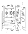
Figur 1 eine Darstellung des kommutierten Motors mit Turbine gemäß der Erfindung, teilweise geschnitten,Figur 2 eine Ansicht der Turbine mit Ansaug- und Auslaßöffnungen,Figur 3 eine stirnseitige Ansicht der Motorturbinenanordnung gemäß der Erfindung mit Darstellung der Ansaug- bzw. Auslaßschlitze für Kühlluft,Figur 4 eine schematische Darstellung von Stator und Rotor des Motors im Längsschnitt mit Darstellung der Drehzahlregelung über einen Hallsensor,Figur 5 den Stator und Rotor nachFigur 4 im Querschnitt mit Darstellung der verengten Luftspaltausgestaltung,Figur 6 den Rotor mit dem Lüfterrad auf der Rotorwelle mit Darstellung der Lagerbereiche in einer Einzelteildarstellung,Figur 7 den Rotor mit Darstellung der konischen Halterung der Permanentmagnete in Detaildarstellung,Figur 8 eine stirnseitige Ansicht des Rotors nachFigur 7,Figur 9 das Schaltbild eines Frequenzumrichters für den Betrieb des kommutierten Motors nach der Erfindung.
- FIG. 1 shows a representation of the commutated motor with turbine according to the invention, partly in section,
- FIG. 2 shows a view of the turbine with intake and exhaust openings,
- FIG. 3 shows an end view of the engine turbine arrangement according to the invention, showing the intake and exhaust slots for cooling air,
- FIG. 4 shows a schematic illustration of the stator and rotor of the motor in longitudinal section, showing the speed control via a Hall sensor,
- FIG. 5 shows the stator and rotor according to FIG. 4 in cross section, showing the narrowed air gap configuration,
- 6 shows the rotor with the fan wheel on the rotor shaft with illustration the storage areas in a single part representation,
- FIG. 7 the rotor with a representation of the conical holder of the permanent magnets in a detailed representation,
- FIG. 8 shows an end view of the rotor according to FIG. 7,
- Figure 9 shows the circuit diagram of a frequency converter for the operation of the commutated motor according to the invention.
Aus Figur 1 ist der Motor 1 mit angesetzter Turbine 10 ersichtlich, wobei der Motor 1 aus Stator 2 mit Erregerwicklungen bzw. Statorwicklungen 3 besteht und aus einem Rotor 5.1 shows the
Stirnseitig ist der Motor durch eine Abdeckung 32 abgedeckt und weist Ansaugschlitze 29 für Kühlluft auf, wobei ein Lüfterrad 9 die Kühlluft über die Ansaugschlitze 29 ansaugt und über Auslaßschlitze 16 ausbläst.At the end, the motor is covered by a
Auf der Rotorwelle 8 ist sowohl das Lüfterrad 9 gelagert als auch der Turbinenläufter 11 und zwar im Bereich der oberen Motorlagerung an einem durchgehend ausgebildeten oberen Lagerschild 12, welches in unmittelbarer Nähe der Lagerung für das Lüfterrad 9 eine Lagerung 19 für den Turbinenläufer 11 ausbildet. Am Umfang der Turbine 10 sind Auslaßöffnungen 17 vorgesehen, wobei nach Figur 2 der Ansaugluftstrom durch eine Ansaugöffnung 31 der Turbine eintritt. Im unteren Bereich ist die Turbine an einem unteren Lager 30 gelagert, welches wegen der Entfernung zum Motor ansich in Bezug auf Wärmeentwicklung nur gering belastet wird.Both the
Das Lüfterrad 9 fördert die Kühlluft nach Art eines Ventilators über Auslaßschlitze 16 ins Freie und kühlt gleichzeitig auch das obere Lagerschild 12 für die Lagerung 13 des oberen Turbinenlagers, so daß eine übermässige Wärmeentwicklung dieser Lagerbereiche vermieden wird.The
Das obere Lagerschild weist im Bereich des Turbinenläufers 11 im Querschnitt im Winkel zueinander verlaufende Ausnehmungen auf, so daß in diesem Bereich die Abluft der Turbine vorteilhaft das Lagerschild 12 kühlt, wobei zusätzlich das Lagerschild durch das Lüfterrad 9 gekühlt wird, insbesondere in Verbindung mit einer abgerundeten Ausformung 15 im Lagerschild, an welcher die ausströmende Kühlluft entlang strömt. Das Lüfterrad 9 ist hierbei in Hinsicht auf die Lagerung in unmittelbarer Nähe des Turbinenläufers 11 angeordnet, und zwar im Bereich eines gemeinsamen oberen Lagerschildes 12, wodurch hier in Verbindung mit benachbarten Austrittsorten für die Kühlluft des Motors und die Abluft der Turbine eine besonders vorteilhafte Motor- bzw. Lagerkühlung erreicht wird.The upper bearing plate has, in the area of the
In Figur 3 sind in detaillierter Darstellung nach einer stirnseitigen Ansicht her die Ansaugschlitze 29 des Lüfterrades 9 für die Kühl1uft des Motors dargestellt, sowie die stirnseitigen Auslaßschlitze 16 des Lüfterrades 9. In Verbindung mit der benachbarten Anordnung der Auslaßöffnungen 17 für die Abluft der Turbine 10 wird eine weitgehende gemeinsam wirkende Abluftführung von Kühlluft und Abluft erzielt, wobei die austretenden Luftströme sich gegenseitig mitreissen, was einer erhöhten Kühlung vom Motor bzw. der Lagerung zugute kommt.In FIG. 3, the
In Figur 3 ist weiterhin die stirnseitige Abdeckung 32 dargestellt, von der Anschlüsse 33 ausgehen bzw. münden, um dort den Frequenzumrichter nach Figur 9 anzuschließen.In FIG. 3, the
Die Figur 4 zeigt im Längsschnitt detailliert den Motor 1, bestehend aus Stator 2 und Rotor 5, wobei die Erregerwicklungen 3 und die paketweise Anordnung von Stator- und Rotorblechen dargestellt ist. Der Rotor 5 bewegt sich im Bereich eines Luftspalts 4, wobei über dem Stator 2 Permanentmagnete 7 nach Art von Ringschalen auf dem Rotor angeordnet sind.Figure 4 shows in longitudinal section in detail the
Im Bereich der Rotorwelle sind an dieser ein oder mehrere Permenentmagnete 25 angeordnet, denen ein Hallsensor 26 gegenüber steht, wodurch bei Drehung des Rotors 5 im Hallsensor 26 Impulse erzeugt werden, welche den Frequenzumrichter nach Figur 9 an den Eingängen C,D ansteuern.In the area of the rotor shaft, one or more
Im Querschnitt der Motorenanordnung nach Figur 5 ist bei sonst nach Figur 4 gleichen Bezugszahlen insbesondere die Ausgestaltung des Luftspalts 4 ersichtlich, wobei von einer Statorwicklung 3 bis zur nächsten der Luftspalt 4 eine stetig zunehmende Verengung 24 durchführt, wodurch eine stets gleiche Anlaufrichtung des Motors erreicht wird.In the cross-section of the motor arrangement according to FIG. 5, the design of the
Die Permanentmagnete 7 sind im Ausführungsbeispiel nach Figur 5 als Ringschalen ausgestaltet und umgeben schalenförmig in Aneinanderreihung den Rotor 5. Die Anzahl der Permanentmagnete 7 richtet sich nach der gewünschten Polzahl in Verbindung mit den am Stator verteilt angeordneten Erregerwicklungen 3. Beim Ausführungsbeispiel nach Figur 5 sind bei vier Erregerwicklungen, die im übrigen dreiecksförmig innerhalb der Statornuten angeordnet sind, vier entsprechende Permanentmagnete 7 vorgesehen.In the exemplary embodiment according to FIG. 5, the
In Figur 6 ist in einer Detailzeichnung die Rotorwelle 8 mit dem Rotor 5 und dem Lüfterrad 9 dargestellt. Hierbei wird insbesondere in Verbindung mit Figur 7 die Ausgestaltung der Permanentmagnete 7 als Ringschalen 18 deutlich. Die Ringschalen 18 weisen an ihren Längsseiten konische Abschrägungen 20 auf, die sich in Richtung zur Rotorwelle hin erweitern.A detailed drawing of the
Die stirnseitig am Rotor 5 angeordneten Deckel 21 weisen demgegenüber ebenfalls konische Abschrägungen 22 entgegengesetzter Neigung auf und umfassen im Randbereich des Rotors 5 die Permanentmagnete 7, so daß hierdurch auch bei höheren Drehzahlen ein sicherer Zusammenhalt des Rotors erreicht wird.The
Nach Figur 7 werden die Deckel 21 im Randbereich von Klemmschrauben 23 durchgriffen, ebenfalls ersichtlich nach Figur 8, wodurch die Deckel 21 im Bereich der konischen Abschrägungen 22 einen sicheren Zusammenhalt mit den Permanentmagneten 7 eingehen, insbesondere in den Randbereichen, wo die Ringschalen 18 konische Abschrägungen 20 entgegengesetzter Neigung aufweisen.According to FIG. 7, the
Aus Figur 6 ist noch ersichtlich, daß auf der Rotorwelle im direkten Anschluß an das Lüfterrad 9 eine obere Lagerung 13 für die Turbine vorgesehen ist, wobei an dieser Lagerung 13 nach Figur 1 das obere Lagerschild 12 ansetzt und hier in Verbindung mit der Belüftung des Lagerschildes sowohl durch das Lüfterrad 9 als auch durch den Turbinenläufer 11 eine besonders vorteilhafte Kühlung des Motors, insbesondere der Erregerwicklung 3 und der Lageranordnung, insbesondere des oberen Lagers 13, erreicht wird. Die Rotorwelle 8 ist demnach in einem Lager 34 geführt, welches durch eine Abdeckung 32 nach Figur 1 geschützt ist, und weiterhin ist das Lager 13 im Bereich des oberen Lagerschildes 12 angeordnet, wobei dieses Lager sowohl radial wirkende Kräfte des Lüfterrades 9 als auch vergleichbare Kräfte ausgehend vom Turbinenläufer 11, aufnimmt. Weiterhin wird der Turbinenläufer 11 im Bereich eines unteren Lagers 30 an der Rotorwelle 8 gehalten in Verbindung mit einem hier nicht näher dargestellten Lagerring.From Figure 6 it can also be seen that an
Aus Figur 7 sind in der vergrößerten Detailzeichnung besonders deutlich die Längsseiten 19 der Permanentmagnete 7 ersichtlich, die im Bereich ihrer konischen Abschrägung 20 von gleichartigen Abschrägungen 22 entgegengesetzter Richtung ausgehend von den Deckein 21 gehalten werden.The
In Figur 9 ist als Ausführungsbeispiel ein Frequenzumrichter 27 dargestellt mit einem Gegen-AB, wo über Inverter in Verbindung mit einer Vergatterung durch UND-Glieder die Ansteuerfrequenz Leistungstreibern 28, die im Gegentakt angeordnet sind, zugeführt wird.FIG. 9 shows an exemplary embodiment of a
Weiterhin wird über den Eingang C,D ein Regelimpuls, der vom Hallsensor 26 erzeugt wird, zugeführt, der im weiteren über Verstärkungsglieder verstärkt wird und nach einer Abfrage der Ansteuerfrequenz nach Art einer Regelung Steuereingängen der Endstufen 28 zugeführt wird. Die Endstufen 28 werden von einer nicht näher dargestellten Versorgungsspannung versorgt und steuern den Motor an ihren Ausgängen über Leistungstreiber T1, T2 bzw. T3 und T4 an. Weiterhin sind Schaltglieder zur Frequenzkompensation und zur Unterdrückung von Störungen bzw. Anschwingvorgängen vorgesehen. Durch Erhöhen bzw. Erniedrigen der Ansteuerfrequenz am Eingang des Frequenzumrichters kann der Motor in beliebige auch sehr hohe Drehzahlen gefahren werden, wobei über den Hallsensor 26 eine Nachregelung der erwünschten Drehzahl durch Ansteuerung der Endstufen 28 erfolgt.Furthermore, a control pulse, which is generated by the
- 1 Motor1 engine
- 2 Stator2 stator
- 3 Erregerwicklung3 excitation winding
- 4 Luftspalt4 air gap
- 5 Rotor5 rotor
- 6 Rotorblech6 rotor plate
- 7 Permanentmagnete7 permanent magnets
- 8 Rotorwelle8 rotor shaft
- 9 Lüfterrad9 fan wheel
- 10 Turbine10 turbine
- 11 Turbinenläufer A,B,D,D-Eingänge11 turbine rotors A, B, D, D inputs
- 12 oberes Lagerschild12 upper end shield
- 13 Lagerung13 storage
- 14 Ausnehmung14 recess
- 15 Ausformung15 formation
- 16 Auslaßschlitze16 outlet slots
- 17 Auslaßöffnung17 outlet opening
- 18 Ringschale18 ring bowl
- 19 Längsseite19 long side
- 20 Abschrägung20 bevel
- 21 Deckel21 lid
- 22 Abschrägung22 bevel
- 23 Klemmschraube23 clamping screw
- 24 Verengung24 narrowing
- 25 Permanentmagnet25 permanent magnet
- 26 Hallsensor26 Hall sensor
- 27 Frequenzumrichter27 frequency converters
- 28 Endstufe28 power amplifier
- 29 Ansaugschlitz29 suction slot
- 30 unteres Lager30 lower warehouse
- 31 Ansaugöffnung31 suction opening
- 32 Abdeckung32 cover
- 33 Anschlüsse33 connections
- 34 Lager34 bearings
Claims (6)
dadurch gekennzeichnet, daß am Umfang des Rotors (5) nach Art von Ringschalen (18) Permanentmagnete (7) in Aneinanderreihung angeordnet sind, wobei die Längsseiten (19) der Permanentmagnete (7) eine konische Abschrägung (20) aufweisen und in Richtung zur Rotorwelle (8) konisch erweitert ausgebildet sind und hierbei die Permanentmagnete (7) an den Längsseiten (19) ringförmig von stirnseitigen Deckein (21) des Rotors (5) umfaßt werden, die entsprechende konische Abschrägungen (22) entgegengesetzter Neigung aufweisen.2. Electronically commutated motor according to claim 1,
characterized in that permanent magnets (7) are arranged in a row on the circumference of the rotor (5) in the manner of ring shells (18), the long sides (19) of the permanent magnets (7) having a conical bevel (20) and in the direction of the rotor shaft (8) are of flared design and in this case the permanent magnets (7) on the long sides (19) are encircled by end faces (21) of the rotor (5) which have corresponding conical bevels (22) of opposite inclination.
dadurch gekennzeichnet, daß die stirnseitigen Deckel (21) des Rotors (5) in Randnähe von Klemmschrauben (23) durchgriffen werden, welche den Randbereich der Deckel (21) mit der Abschrägung (22) gegen die konische Abschrägung (20) der Permanentmagnete (7) pressen.3. Electronically commutated motor according to claim 2,
characterized in that the front covers (21) of the rotor (5) in the vicinity of the edge are penetrated by clamping screws (23) which cover the edge region of the cover (21) with the bevel (22) against the conical bevel (20) of the permanent magnets (7 ) press.
dadurch gekennzeichnet, daß der Luftspalt (4) zwischen dem Permanentmagneten (7) und dem Stator (2) in wechselnder Anordnung entsprechend der Polzahl des Stators verengt ausgebildet ist, wobei ausgehend von einer Erreger- bzw. Statorwicklung (3) bis zur darauffolgenden Wicklung eine stetig zunehmende Verengung (24) vorgesehen ist, um einen stets gleichen Anlauf des Motors (1) in Richtung der Verengung (24) zu erzielen.4. Electronically commutated motor according to claims 1 and 2,
characterized in that the air gap (4) between the permanent magnet (7) and the stator (2) is formed in an alternating arrangement according to the number of poles of the stator, starting from an excitation or stator winding (3) up to the subsequent winding Constantly increasing constriction (24) is provided in order to always achieve the same start of the motor (1) in the direction of the constriction (24).
dadurch gekennzeichnet, daß an der Rotorwelle (8) eine oder mehrere Permanentmagnete (25) am Umfang angeordnet sind, wobei Regelimpluse gemäß der Rotation der Rotorwelle (8) über einen Hallsensor (26) einer Frequenzsteuerung durchgeführt werden.5. Electronically commutated motor according to claim 1,
characterized in that one or more permanent magnets (25) are arranged on the periphery of the rotor shaft (8), with control impluses being carried out according to the rotation of the rotor shaft (8) via a Hall sensor (26) of a frequency control.
dadurch gekennzeichnet, daß eine elektronische Kommutierung des Motors (1) in Verbindung mit einem Frequenzumrichter (27) vorgesehen ist, wobei eine Steuerfrequenz entsprechend der gewünschten Drehzahl und weiterhin Regelimpulse des Hallsensors (26) Eingängen (A,B) bzw. (C,D) des Frequenzumrichters (27) zugeführt werden und am Ausgang des Frequenzumrichters über im Gegentakt gesteuerte Endstufen (28) die Statorwicklungen (3) des Motors (1) der Reihe nach angesteuert werden.6. Electronically commutated motor according to claims 1 to 5,
characterized in that electronic commutation of the motor (1) is provided in connection with a frequency converter (27), a control frequency corresponding to the desired speed and further control pulses from the Hall sensor (26) inputs (A, B) or (C, D ) of the frequency converter (27) are supplied and the stator windings (3) of the motor (1) are controlled in sequence at the output of the frequency converter via push-pull output stages (28).
Priority Applications (1)
| Application Number | Priority Date | Filing Date | Title |
|---|---|---|---|
| AT90112010T ATE100691T1 (en) | 1989-07-14 | 1990-06-25 | ELECTRONICALLY COMMUTATED MOTOR FOR VACUUM CLEANERS AND LIKE. |
Applications Claiming Priority (2)
| Application Number | Priority Date | Filing Date | Title |
|---|---|---|---|
| DE3923267A DE3923267A1 (en) | 1989-07-14 | 1989-07-14 | ELECTRONICALLY COMMUTED MOTOR FOR VACUUM CLEANERS AND THE LIKE |
| DE3923267 | 1989-07-14 |
Publications (3)
| Publication Number | Publication Date |
|---|---|
| EP0413113A2 true EP0413113A2 (en) | 1991-02-20 |
| EP0413113A3 EP0413113A3 (en) | 1991-05-22 |
| EP0413113B1 EP0413113B1 (en) | 1994-01-26 |
Family
ID=6385005
Family Applications (1)
| Application Number | Title | Priority Date | Filing Date |
|---|---|---|---|
| EP90112010A Expired - Lifetime EP0413113B1 (en) | 1989-07-14 | 1990-06-25 | Electronically commutated motor for vacuum cleaner and the like |
Country Status (9)
| Country | Link |
|---|---|
| US (1) | US5394041A (en) |
| EP (1) | EP0413113B1 (en) |
| JP (1) | JP2630669B2 (en) |
| KR (1) | KR0156243B1 (en) |
| AT (1) | ATE100691T1 (en) |
| BR (1) | BR9003362A (en) |
| DE (2) | DE3923267A1 (en) |
| DK (1) | DK0413113T3 (en) |
| ES (1) | ES2050307T3 (en) |
Cited By (5)
| Publication number | Priority date | Publication date | Assignee | Title |
|---|---|---|---|---|
| GB2286293A (en) * | 1993-12-23 | 1995-08-09 | London Innovation Limited | Adjustable stator: winding construction: cooling and commutator construction inan electric machine |
| EP0766366A1 (en) * | 1995-09-29 | 1997-04-02 | BITRON S.p.A. | Power steering unit |
| EP0784369A1 (en) | 1996-01-11 | 1997-07-16 | SA-Patent AG | Electric motor driven bypass fan |
| EP1025792A2 (en) * | 1999-02-08 | 2000-08-09 | AMETEK ITALIA S.r.l. | Electrically powered aspirator unit with impeller for cooling the motor |
| CN1306896C (en) * | 2004-10-27 | 2007-03-28 | 金骏达电机制造厂有限公司 | Constructive method and coupling structure for metal dust suction subassembly driven by micro motor |
Families Citing this family (21)
| Publication number | Priority date | Publication date | Assignee | Title |
|---|---|---|---|---|
| EP0552756A1 (en) * | 1992-01-21 | 1993-07-28 | Shinko Electric Co. Ltd. | Article storage house in a clean room |
| US5708316A (en) * | 1992-10-23 | 1998-01-13 | Nippondenso Co., Ltd. | Altenator for a vehicle |
| US5691590A (en) * | 1992-10-23 | 1997-11-25 | Nippondenso Co., Ltd. | Alternator with magnetic noise reduction mechanism |
| US5574321A (en) * | 1994-05-04 | 1996-11-12 | Emerson Electric Co. | Integral refrigerator motor fan blades |
| DE4416299A1 (en) * | 1994-05-09 | 1995-11-16 | Abb Management Ag | Electrical machine with an axial fan |
| RU2098908C1 (en) * | 1995-03-07 | 1997-12-10 | Товарищество с ограниченной ответственностью "ПЭТРО-ФЭСТ" | Valve-type motor |
| US5751079A (en) * | 1996-10-17 | 1998-05-12 | Ford Motor Company | Alternator with internal and external fans |
| US6166462A (en) * | 1998-05-04 | 2000-12-26 | Ametek, Inc. | Bypass motor/fan assembly having separate working air passages |
| FR2778327B1 (en) * | 1998-05-07 | 2000-06-30 | Seb Sa | SUCTION DEVICE |
| US6439843B1 (en) | 2000-11-16 | 2002-08-27 | Ametek, Inc. | Motor/fan assembly having a radial diffuser bypass |
| JP4118548B2 (en) * | 2001-11-06 | 2008-07-16 | 株式会社デンソー | Vehicle alternator |
| GB0202835D0 (en) * | 2002-02-07 | 2002-03-27 | Johnson Electric Sa | Blower motor |
| US7252482B2 (en) * | 2004-08-24 | 2007-08-07 | Beckett Corporation | Motor driven pump with improved motor cooling air flow |
| GB0724837D0 (en) * | 2007-12-20 | 2008-01-30 | Edwards Ltd | vacuum pump |
| CN101592158A (en) * | 2008-05-28 | 2009-12-02 | Gmj设计公司 | Improved cooling airflow electric motor driving pump |
| US20110091330A1 (en) * | 2009-10-21 | 2011-04-21 | Deoliviera Marcelo | Condensate Removal Pump Controller Using Acoustic Liquid Level Sensor |
| CN102114483B (en) * | 2009-12-31 | 2015-04-15 | 曾世雄 | Industrial dedusting device |
| CN102784994B (en) * | 2012-05-24 | 2015-04-22 | 盐城市康杰机械制造有限公司 | Circulating fan of aluminium soldering preheating furnace |
| CN203384069U (en) * | 2013-07-17 | 2014-01-08 | 中山大洋电机股份有限公司 | Induced draft fan |
| US9453427B2 (en) | 2013-10-30 | 2016-09-27 | General Electric Company | Systems and methods for purging an aft joint of a last stage wheel |
| KR102306127B1 (en) * | 2017-05-30 | 2021-09-29 | 엘지전자 주식회사 | motor assembly |
Citations (4)
| Publication number | Priority date | Publication date | Assignee | Title |
|---|---|---|---|---|
| FR1204047A (en) * | 1958-07-10 | 1960-01-22 | Tornado A G | Electric dust vacuum |
| DE1941418B2 (en) * | 1969-08-14 | 1977-05-12 | Hanning Elektro-Werke Robert Hanning, 4800 Bielefeld | Driving motor for hot air circulating fan - uses air flow through hollow motor shaft to cool inboard bearing |
| US4527960A (en) * | 1984-02-03 | 1985-07-09 | General Signal Corporation | Bearing air seal for vacuum cleaner motor |
| EP0192599A2 (en) * | 1985-02-22 | 1986-08-27 | AMETEK Inc. | Quiet by-pass vacuum motor |
Family Cites Families (48)
| Publication number | Priority date | Publication date | Assignee | Title |
|---|---|---|---|---|
| GB309294A (en) * | 1928-03-29 | 1929-04-11 | Ml Magneto Syndicate Ltd | Improvements relating to dynamo electric machines |
| DE668436C (en) * | 1935-11-02 | 1938-12-03 | Siemens Schuckertwerke Akt Ges | Winding-free runner for electrical machines with prism-shaped pole pieces of trapezoidal cross-section consisting of permanent magnet steel |
| US2601517A (en) * | 1949-11-01 | 1952-06-24 | Dorothy C Hammes | Synchronous motor |
| US2726807A (en) * | 1950-09-28 | 1955-12-13 | Finnell System Inc | Vacuum apparatus for water and dirt removal |
| DE1139197B (en) * | 1954-04-08 | 1962-11-08 | Hermann Papst | Rotary field machine with hysteretic effect |
| US2822122A (en) * | 1955-05-06 | 1958-02-04 | American Machine & Metals | Vacuum cleaner motor and fan assembly |
| US2985779A (en) * | 1957-09-09 | 1961-05-23 | Gen Motors Corp | Permanent magnet rotor construction |
| DE1212625B (en) * | 1963-10-23 | 1966-03-17 | Licentia Gmbh | Holder of a thin-walled permanent magnet ring made of oxide material in the runner of an electric motor |
| US3263908A (en) * | 1964-05-15 | 1966-08-02 | Nat Union Electric Corp | Cooling arrangement for a vacuum cleaner motor or the like |
| FR1440924A (en) * | 1965-05-13 | 1966-06-03 | Nat Union Electric Corp | Cooling device for vacuum cleaner motor and the like |
| DE1628304A1 (en) * | 1967-04-14 | 1971-08-12 | Korrokunststoff Korrosionstech | Radial fan |
| US3610975A (en) * | 1969-07-30 | 1971-10-05 | Westinghouse Electric Corp | Dynamoelectric machine with improved cooling means |
| JPS5128322B1 (en) * | 1970-11-14 | 1976-08-18 | ||
| DE2003905A1 (en) * | 1970-01-29 | 1971-08-05 | Siemens Elektrogeraete Gmbh | Vacuum cleaner fan with self-ventilated drive motor |
| CA977909A (en) * | 1972-08-18 | 1975-11-18 | Christopher R. Smallbone | Motor-fan device for vacuum cleaners |
| US3875436A (en) * | 1973-07-16 | 1975-04-01 | Scott & Fetzer Co | Double insulated vacuum cleaner motor housing |
| JPS5128610A (en) * | 1974-09-04 | 1976-03-11 | Hitachi Ltd | Museiryushimoota no sokudoseigyokairo |
| DE2640899A1 (en) * | 1975-09-12 | 1977-03-24 | Plessey Handel Investment Ag | ELECTRIC MOTOR |
| US4120616A (en) * | 1975-10-06 | 1978-10-17 | Breuer Electric Manufacturing Company | Vacuum cleaner-blower assembly with sound absorbing arrangement |
| GB1565537A (en) * | 1975-10-23 | 1980-04-23 | Hitachi Ltd | Electric motor |
| USRE32027E (en) * | 1977-05-23 | 1985-11-12 | Ametek, Inc. | Wet pick-up vacuum unit motor bearing air seal |
| DE2945865A1 (en) * | 1979-11-14 | 1981-06-04 | Robert Bosch Gmbh, 7000 Stuttgart | Vacuum cleaner fan for hand tool waste exhaust - has additional opening ensuring adequate cooling of motor |
| DE3010435A1 (en) * | 1980-03-19 | 1981-09-24 | Papst-Motoren Kg, 7742 St Georgen | COLLECTORLESS DC MOTOR |
| JPS576591A (en) * | 1980-06-11 | 1982-01-13 | Japan Servo Co Ltd | Direct current brushless motor and drive controller thereof |
| US4479078A (en) * | 1980-06-20 | 1984-10-23 | Kollmorgen Technologies Corporation | Brushless motor controller |
| DD157886A1 (en) * | 1981-04-03 | 1982-12-15 | Elektrogeraete Ingbuero Veb | MOTORGEBLAESEEINHEIT |
| DE3145232A1 (en) * | 1981-11-13 | 1983-06-01 | Quick-Rotan Elektromotoren GmbH, 6100 Darmstadt | DRIVE FOR WORKING MACHINES, IN PARTICULAR INDUSTRIAL SEWING MACHINES |
| JPH0728553B2 (en) * | 1982-03-31 | 1995-03-29 | 株式会社日立製作所 | Motor drive circuit |
| US4528485A (en) * | 1982-04-13 | 1985-07-09 | General Electric Company | Electronically commutated motor, method of operating such, control circuit, laundry machine and drive therefor |
| DE3239665A1 (en) * | 1982-06-09 | 1983-12-15 | Ebm Elektrobau Mulfingen Gmbh & Co, 7119 Mulfingen | DC motor having no commutator |
| DE3229458A1 (en) * | 1982-08-06 | 1984-02-09 | Ryoji Nerima Tokyo Minegishi | Fan with a motor |
| JPS5959054A (en) * | 1982-09-27 | 1984-04-04 | Fanuc Ltd | Permanent magnet field rotor structure |
| JPS6024182U (en) * | 1983-07-22 | 1985-02-19 | 株式会社リコー | hall motor |
| DE3427565A1 (en) * | 1984-07-26 | 1986-02-06 | Licentia Patent-Verwaltungs-Gmbh, 6000 Frankfurt | Radial-flow fan driven by an electric motor |
| US4698534A (en) * | 1985-02-22 | 1987-10-06 | Ametek, Inc. | Quiet by-pass vacuum motor |
| JPS61199448A (en) * | 1985-02-28 | 1986-09-03 | Fanuc Ltd | Permanent magnet field rotor assembly |
| US4669952A (en) * | 1985-05-17 | 1987-06-02 | Ametek, Inc. | Quiet by-pass vacuum motor |
| US4680515A (en) * | 1985-05-21 | 1987-07-14 | Crook James C | Digital speed control of motors |
| JPS61280752A (en) * | 1985-06-05 | 1986-12-11 | Oopack Kk | Brushless dc rotary electric machine |
| CH670017A5 (en) * | 1986-03-03 | 1989-04-28 | Papst Motoren Gmbh & Co Kg | Miniature permanent magnet electric motor - has narrow cylindrical air-gap and integral outer housing and stator of sintered metal |
| US4668898A (en) * | 1986-04-21 | 1987-05-26 | General Electric Company | Electronically commutated motor |
| US4642502A (en) * | 1986-04-24 | 1987-02-10 | General Motors Corporation | Dynamoelectric machine with permanent magnet and magnet mounting surface arrangement |
| US4801834A (en) * | 1986-04-30 | 1989-01-31 | General Electric Company | Rotor assembly |
| FR2603667B1 (en) * | 1986-09-10 | 1990-09-28 | Etri Sa | CENTRIFUGAL FAN DRIVEN BY AN ELECTRONICALLY SWITCHED DIRECT CURRENT MOTOR |
| US4851017A (en) * | 1987-10-07 | 1989-07-25 | Rexair, Inc. | Radial cooling fan for vacuum cleaner motor |
| US4883982A (en) * | 1988-06-02 | 1989-11-28 | General Electric Company | Electronically commutated motor, blower integral therewith, and stationary and rotatable assemblies therefor |
| US4973872A (en) * | 1988-10-07 | 1990-11-27 | Emerson Electric Co. | Dynamoelectric machine rotor assembly with improved magnet retention stucture |
| SI8912097B (en) * | 1989-10-30 | 1999-04-30 | Iskra-Elektromotorji, P.O., | Single-phase direct current motor without brushes with high speed and high power |
-
1989
- 1989-07-14 DE DE3923267A patent/DE3923267A1/en not_active Withdrawn
-
1990
- 1990-06-25 AT AT90112010T patent/ATE100691T1/en active
- 1990-06-25 DK DK90112010.5T patent/DK0413113T3/en active
- 1990-06-25 EP EP90112010A patent/EP0413113B1/en not_active Expired - Lifetime
- 1990-06-25 ES ES90112010T patent/ES2050307T3/en not_active Expired - Lifetime
- 1990-06-25 DE DE90112010T patent/DE59004393D1/en not_active Expired - Fee Related
- 1990-07-11 KR KR1019900010438A patent/KR0156243B1/en not_active IP Right Cessation
- 1990-07-13 BR BR909003362A patent/BR9003362A/en not_active IP Right Cessation
- 1990-07-16 JP JP2189255A patent/JP2630669B2/en not_active Expired - Lifetime
-
1994
- 1994-04-04 US US08/222,504 patent/US5394041A/en not_active Expired - Lifetime
Patent Citations (4)
| Publication number | Priority date | Publication date | Assignee | Title |
|---|---|---|---|---|
| FR1204047A (en) * | 1958-07-10 | 1960-01-22 | Tornado A G | Electric dust vacuum |
| DE1941418B2 (en) * | 1969-08-14 | 1977-05-12 | Hanning Elektro-Werke Robert Hanning, 4800 Bielefeld | Driving motor for hot air circulating fan - uses air flow through hollow motor shaft to cool inboard bearing |
| US4527960A (en) * | 1984-02-03 | 1985-07-09 | General Signal Corporation | Bearing air seal for vacuum cleaner motor |
| EP0192599A2 (en) * | 1985-02-22 | 1986-08-27 | AMETEK Inc. | Quiet by-pass vacuum motor |
Cited By (8)
| Publication number | Priority date | Publication date | Assignee | Title |
|---|---|---|---|---|
| GB2286293A (en) * | 1993-12-23 | 1995-08-09 | London Innovation Limited | Adjustable stator: winding construction: cooling and commutator construction inan electric machine |
| US6040645A (en) * | 1993-12-23 | 2000-03-21 | London Innovation Ltd. | Electrical machines |
| US6459179B1 (en) | 1993-12-23 | 2002-10-01 | Cedric Lynch | Electrical machines |
| EP0766366A1 (en) * | 1995-09-29 | 1997-04-02 | BITRON S.p.A. | Power steering unit |
| EP0784369A1 (en) | 1996-01-11 | 1997-07-16 | SA-Patent AG | Electric motor driven bypass fan |
| EP1025792A2 (en) * | 1999-02-08 | 2000-08-09 | AMETEK ITALIA S.r.l. | Electrically powered aspirator unit with impeller for cooling the motor |
| EP1025792A3 (en) * | 1999-02-08 | 2002-05-29 | AMETEK ITALIA S.r.l. | Electrically powered aspirator unit with impeller for cooling the motor |
| CN1306896C (en) * | 2004-10-27 | 2007-03-28 | 金骏达电机制造厂有限公司 | Constructive method and coupling structure for metal dust suction subassembly driven by micro motor |
Also Published As
| Publication number | Publication date |
|---|---|
| KR0156243B1 (en) | 1998-12-15 |
| ATE100691T1 (en) | 1994-02-15 |
| ES2050307T3 (en) | 1994-05-16 |
| JP2630669B2 (en) | 1997-07-16 |
| JPH0390119A (en) | 1991-04-16 |
| EP0413113B1 (en) | 1994-01-26 |
| BR9003362A (en) | 1991-08-27 |
| DE59004393D1 (en) | 1994-03-10 |
| DE3923267A1 (en) | 1991-01-24 |
| EP0413113A3 (en) | 1991-05-22 |
| DK0413113T3 (en) | 1994-05-24 |
| KR910003895A (en) | 1991-02-28 |
| US5394041A (en) | 1995-02-28 |
Similar Documents
| Publication | Publication Date | Title |
|---|---|---|
| EP0413113B1 (en) | Electronically commutated motor for vacuum cleaner and the like | |
| DE3740725C2 (en) | ||
| EP1051797B1 (en) | Electric machine | |
| DE2433087C2 (en) | Built-in fan for ventilating the front of a flat installation wall | |
| EP1362404B1 (en) | Electrical machine | |
| DE3932802A1 (en) | Brushless high speed DC vacuum cleaner motor - has electronic commutation for hazardous applications using Hall-effect sensors in permanent magnet rotor with in-built stator current limit | |
| EP0345796A2 (en) | Ventilator driven by an electric motor | |
| EP1389824A1 (en) | Electric machine system | |
| EP0854560A1 (en) | Heat dissipation concept for electric drive | |
| DE3122655A1 (en) | "ACTUAL VALUE DEVICE" | |
| DE102019218437A1 (en) | Rotor for an electric machine and method for manufacturing a rotor | |
| DE2245009B2 (en) | Canned motor for a pump unit with a plastic housing and a rotor combined with a pump wheel | |
| EP2429065B1 (en) | Electric machine with permanent magnet excitation | |
| EP0454664B1 (en) | Electric machine with vertical shaft | |
| EP1026507A2 (en) | Electric motor with rpm-monitor | |
| EP1081386A2 (en) | Axial flux electric motor | |
| DE2742962A1 (en) | Centrifugal fan for vacuum cleaner - has permanent magnet DC motor with magnet coupled to impeller | |
| DE4222131C2 (en) | Ventilation device for pressure ventilation of surface-ventilated electrical machines | |
| DE3232914C1 (en) | Runner for a hysteresis motor | |
| DE10228224B3 (en) | Device for cooling a power generator unit | |
| DE112006002085T5 (en) | Synchronous generator with permanent magnets, mainly welding generator | |
| EP3577745B1 (en) | Cooling of an electric machine | |
| DE4402411C2 (en) | Synchronous motor with permanent magnet excited rotor | |
| CH406888A (en) | Electric angle hand grinder with ventilation | |
| EP1048904A2 (en) | Ventilation unit for a filter and ventilation system, in particular for clean rooms |
Legal Events
| Date | Code | Title | Description |
|---|---|---|---|
| PUAI | Public reference made under article 153(3) epc to a published international application that has entered the european phase |
Free format text: ORIGINAL CODE: 0009012 |
|
| AK | Designated contracting states |
Kind code of ref document: A2 Designated state(s): AT BE CH DE DK ES FR GB GR IT LI LU NL SE |
|
| PUAL | Search report despatched |
Free format text: ORIGINAL CODE: 0009013 |
|
| 17P | Request for examination filed |
Effective date: 19910312 |
|
| AK | Designated contracting states |
Kind code of ref document: A3 Designated state(s): AT BE CH DE DK ES FR GB GR IT LI LU NL SE |
|
| 17Q | First examination report despatched |
Effective date: 19921007 |
|
| GRAA | (expected) grant |
Free format text: ORIGINAL CODE: 0009210 |
|
| STAA | Information on the status of an ep patent application or granted ep patent |
Free format text: STATUS: THE PATENT HAS BEEN GRANTED |
|
| AK | Designated contracting states |
Kind code of ref document: B1 Designated state(s): AT BE CH DE DK ES FR GB GR IT LI LU NL SE |
|
| PG25 | Lapsed in a contracting state [announced via postgrant information from national office to epo] |
Ref country code: GR Free format text: LAPSE BECAUSE OF FAILURE TO SUBMIT A TRANSLATION OF THE DESCRIPTION OR TO PAY THE FEE WITHIN THE PRESCRIBED TIME-LIMIT Effective date: 19940126 |
|
| REF | Corresponds to: |
Ref document number: 100691 Country of ref document: AT Date of ref document: 19940215 Kind code of ref document: T |
|
| REF | Corresponds to: |
Ref document number: 59004393 Country of ref document: DE Date of ref document: 19940310 |
|
| ITF | It: translation for a ep patent filed |
Owner name: STUDIO INTERN. DOTT. COPPI S.N.C. |
|
| REG | Reference to a national code |
Ref country code: ES Ref legal event code: FG2A Ref document number: 2050307 Country of ref document: ES Kind code of ref document: T3 |
|
| REG | Reference to a national code |
Ref country code: DK Ref legal event code: T3 |
|
| GBT | Gb: translation of ep patent filed (gb section 77(6)(a)/1977) |
Effective date: 19940422 |
|
| ET | Fr: translation filed | ||
| EPTA | Lu: last paid annual fee | ||
| PLBE | No opposition filed within time limit |
Free format text: ORIGINAL CODE: 0009261 |
|
| 26N | No opposition filed | ||
| EAL | Se: european patent in force in sweden |
Ref document number: 90112010.5 |
|
| PGFP | Annual fee paid to national office [announced via postgrant information from national office to epo] |
Ref country code: BE Payment date: 20000405 Year of fee payment: 11 |
|
| PGFP | Annual fee paid to national office [announced via postgrant information from national office to epo] |
Ref country code: LU Payment date: 20000530 Year of fee payment: 11 |
|
| PGFP | Annual fee paid to national office [announced via postgrant information from national office to epo] |
Ref country code: ES Payment date: 20000615 Year of fee payment: 11 |
|
| PGFP | Annual fee paid to national office [announced via postgrant information from national office to epo] |
Ref country code: FR Payment date: 20000628 Year of fee payment: 11 Ref country code: SE Payment date: 20000628 Year of fee payment: 11 |
|
| PGFP | Annual fee paid to national office [announced via postgrant information from national office to epo] |
Ref country code: NL Payment date: 20000629 Year of fee payment: 11 |
|
| PGFP | Annual fee paid to national office [announced via postgrant information from national office to epo] |
Ref country code: AT Payment date: 20000630 Year of fee payment: 11 |
|
| PG25 | Lapsed in a contracting state [announced via postgrant information from national office to epo] |
Ref country code: LU Free format text: LAPSE BECAUSE OF NON-PAYMENT OF DUE FEES Effective date: 20010625 Ref country code: AT Free format text: LAPSE BECAUSE OF NON-PAYMENT OF DUE FEES Effective date: 20010625 |
|
| PG25 | Lapsed in a contracting state [announced via postgrant information from national office to epo] |
Ref country code: ES Free format text: LAPSE BECAUSE OF NON-PAYMENT OF DUE FEES Effective date: 20010626 Ref country code: SE Free format text: LAPSE BECAUSE OF NON-PAYMENT OF DUE FEES Effective date: 20010626 |
|
| PG25 | Lapsed in a contracting state [announced via postgrant information from national office to epo] |
Ref country code: BE Free format text: LAPSE BECAUSE OF NON-PAYMENT OF DUE FEES Effective date: 20010630 |
|
| BERE | Be: lapsed |
Owner name: WAP REINIGUNGSSYSTEME G.M.B.H. & CO. Effective date: 20010630 |
|
| PG25 | Lapsed in a contracting state [announced via postgrant information from national office to epo] |
Ref country code: NL Free format text: LAPSE BECAUSE OF NON-PAYMENT OF DUE FEES Effective date: 20020101 |
|
| REG | Reference to a national code |
Ref country code: GB Ref legal event code: IF02 |
|
| EUG | Se: european patent has lapsed |
Ref document number: 90112010.5 |
|
| PG25 | Lapsed in a contracting state [announced via postgrant information from national office to epo] |
Ref country code: FR Free format text: LAPSE BECAUSE OF NON-PAYMENT OF DUE FEES Effective date: 20020228 |
|
| NLV4 | Nl: lapsed or anulled due to non-payment of the annual fee |
Effective date: 20020101 |
|
| PGFP | Annual fee paid to national office [announced via postgrant information from national office to epo] |
Ref country code: CH Payment date: 20020625 Year of fee payment: 13 |
|
| REG | Reference to a national code |
Ref country code: ES Ref legal event code: FD2A Effective date: 20030203 |
|
| PGFP | Annual fee paid to national office [announced via postgrant information from national office to epo] |
Ref country code: DE Payment date: 20030514 Year of fee payment: 14 |
|
| PGFP | Annual fee paid to national office [announced via postgrant information from national office to epo] |
Ref country code: DK Payment date: 20030616 Year of fee payment: 14 |
|
| PG25 | Lapsed in a contracting state [announced via postgrant information from national office to epo] |
Ref country code: LI Free format text: LAPSE BECAUSE OF NON-PAYMENT OF DUE FEES Effective date: 20030630 Ref country code: CH Free format text: LAPSE BECAUSE OF NON-PAYMENT OF DUE FEES Effective date: 20030630 |
|
| REG | Reference to a national code |
Ref country code: CH Ref legal event code: PL |
|
| PG25 | Lapsed in a contracting state [announced via postgrant information from national office to epo] |
Ref country code: DK Free format text: LAPSE BECAUSE OF NON-PAYMENT OF DUE FEES Effective date: 20040630 |
|
| PG25 | Lapsed in a contracting state [announced via postgrant information from national office to epo] |
Ref country code: DE Free format text: LAPSE BECAUSE OF NON-PAYMENT OF DUE FEES Effective date: 20050101 |
|
| REG | Reference to a national code |
Ref country code: DK Ref legal event code: EBP |
|
| PG25 | Lapsed in a contracting state [announced via postgrant information from national office to epo] |
Ref country code: IT Free format text: LAPSE BECAUSE OF NON-PAYMENT OF DUE FEES;WARNING: LAPSES OF ITALIAN PATENTS WITH EFFECTIVE DATE BEFORE 2007 MAY HAVE OCCURRED AT ANY TIME BEFORE 2007. THE CORRECT EFFECTIVE DATE MAY BE DIFFERENT FROM THE ONE RECORDED. Effective date: 20050625 |
|
| PGFP | Annual fee paid to national office [announced via postgrant information from national office to epo] |
Ref country code: GB Payment date: 20080609 Year of fee payment: 19 |
|
| GBPC | Gb: european patent ceased through non-payment of renewal fee |
Effective date: 20090625 |
|
| PG25 | Lapsed in a contracting state [announced via postgrant information from national office to epo] |
Ref country code: GB Free format text: LAPSE BECAUSE OF NON-PAYMENT OF DUE FEES Effective date: 20090625 |