EP0413111B1 - Moteur à onde progressive ultra-sonore à deux ou plusieurs plots - Google Patents
Moteur à onde progressive ultra-sonore à deux ou plusieurs plots Download PDFInfo
- Publication number
- EP0413111B1 EP0413111B1 EP90111985A EP90111985A EP0413111B1 EP 0413111 B1 EP0413111 B1 EP 0413111B1 EP 90111985 A EP90111985 A EP 90111985A EP 90111985 A EP90111985 A EP 90111985A EP 0413111 B1 EP0413111 B1 EP 0413111B1
- Authority
- EP
- European Patent Office
- Prior art keywords
- stator
- rotor
- ultrasonic
- progressive wave
- excited
- Prior art date
- Legal status (The legal status is an assumption and is not a legal conclusion. Google has not performed a legal analysis and makes no representation as to the accuracy of the status listed.)
- Expired - Lifetime
Links
- 230000000750 progressive effect Effects 0.000 title claims abstract 10
- 230000005540 biological transmission Effects 0.000 claims abstract description 4
- 230000005284 excitation Effects 0.000 claims description 19
- 238000000034 method Methods 0.000 claims description 6
- 230000010355 oscillation Effects 0.000 claims description 4
- 239000012858 resilient material Substances 0.000 claims 2
- 230000003534 oscillatory effect Effects 0.000 claims 1
- 239000013013 elastic material Substances 0.000 abstract 1
- 239000000919 ceramic Substances 0.000 description 10
- 230000033001 locomotion Effects 0.000 description 10
- 239000010410 layer Substances 0.000 description 9
- 230000005684 electric field Effects 0.000 description 8
- 230000008602 contraction Effects 0.000 description 7
- 239000002184 metal Substances 0.000 description 2
- 230000010287 polarization Effects 0.000 description 2
- 230000003068 static effect Effects 0.000 description 2
- 230000007704 transition Effects 0.000 description 2
- 238000002604 ultrasonography Methods 0.000 description 2
- 239000012790 adhesive layer Substances 0.000 description 1
- 238000005452 bending Methods 0.000 description 1
- 230000015572 biosynthetic process Effects 0.000 description 1
- 239000011248 coating agent Substances 0.000 description 1
- 238000000576 coating method Methods 0.000 description 1
- 238000010276 construction Methods 0.000 description 1
- 230000008878 coupling Effects 0.000 description 1
- 238000010168 coupling process Methods 0.000 description 1
- 238000005859 coupling reaction Methods 0.000 description 1
- 238000013016 damping Methods 0.000 description 1
- 238000001514 detection method Methods 0.000 description 1
- 230000010339 dilation Effects 0.000 description 1
- 230000000694 effects Effects 0.000 description 1
- HFGPZNIAWCZYJU-UHFFFAOYSA-N lead zirconate titanate Chemical compound [O-2].[O-2].[O-2].[O-2].[O-2].[Ti+4].[Zr+4].[Pb+2] HFGPZNIAWCZYJU-UHFFFAOYSA-N 0.000 description 1
- 229910052451 lead zirconate titanate Inorganic materials 0.000 description 1
- 239000000463 material Substances 0.000 description 1
- 230000001953 sensory effect Effects 0.000 description 1
Images


Classifications
-
- H—ELECTRICITY
- H02—GENERATION; CONVERSION OR DISTRIBUTION OF ELECTRIC POWER
- H02N—ELECTRIC MACHINES NOT OTHERWISE PROVIDED FOR
- H02N2/00—Electric machines in general using piezoelectric effect, electrostriction or magnetostriction
- H02N2/10—Electric machines in general using piezoelectric effect, electrostriction or magnetostriction producing rotary motion, e.g. rotary motors
- H02N2/16—Electric machines in general using piezoelectric effect, electrostriction or magnetostriction producing rotary motion, e.g. rotary motors using travelling waves, i.e. Rayleigh surface waves
- H02N2/166—Motors with disc stator
Definitions
- the present invention relates to an ultrasonic motor in which a drive torque using an ultrasonic oscillator, for. B. a piezoelectric or a magnetostriction element is generated as a drive element.
- Piezoelectric motors such as those used for. B. are known from the application EP-A-0169297, generate rotational or linear movements of a movable part by mechanical waves excited in a piezoelectric ceramic of the stator. Advantages of such motors are u. a. the possibility of generating high torques at user-friendly low speeds, so that a gearbox is not required, a small construction volume with low weight and high energy density and a high holding torque in a passive state.
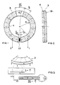
- the vibration stator used in such a motor contains an annular piezoceramic disk which is provided with electrodes and is glued to the actual vibration body.
- Two working electrodes on one side of the ceramic form two separate excitation systems with a metallic vibrating body, which acts as a counter electrode on the other side of the ceramic. Under each of the working electrodes there are alternately differently polarized areas in the ceramic, which in the broadest sense are comparable to the pole pitch of conventional motors.
- the vibrating stator is under axial pressure in contact with a rotor which is provided with a thin coating of suitable plastic on the contact surface.
- the piezo ceramic is excited with high-frequency AC voltage via the electrodes in such a way that mechanical traveling waves are generated in the stator.
- a metal ring or a circular metal disc is used as the actual vibrating body.
- the oscillating body is excited with a frequency (natural frequency) at which the number of radial straight lines polarized in the piezoceramic, ie. H. Straight lines, on which the deflection of the surface is zero, in the desired waveform.
- the angular ranges free of the piezoceramic serve for the sensory detection of engine states, e.g. B. by means of a sensor electrode ES.
- FIG. 2 illustrates how the piezoceramic 3 is arranged between the working electrodes 1, 2 and the counter electrode formed by the metallic oscillating body 4.
- FIGS. 3-5 illustrate the excitation of mechanical waves in the stator by means of piezoceramic elements.
- FIG. 3 schematically shows a disk-shaped piezoceramic segment with a disk thickness z and a linear extension x.
- B. lead zirconate titanate is found when an electric field is applied perpendicular to the surface of the pane when z is small compared to x that the piezoelectric deformation is perpendicular to the direction of the field, i. H. in the x direction is an order of magnitude larger than parallel to the field direction.
- the deformation of the piezoceramic takes place approximately exclusively in the circumferential direction in a circular ring segment.
- FIG. 4a now shows a symmetrically polarized piezoceramic 3a of length L0 with a total of four alternately arranged positively and negatively polarized segments of the respective length L0.
- FIG. 4b shows, by applying an external static electric field, each of the segments is caused to contract or extend by an amount ⁇ L according to its polarization. The reversal of the electric field leads to a change between contraction and elongation in the individual segments (FIG. 4c). Since, with alternating polarization and the same number of positive and negative segments, the contractions and extensions of the ceramic segments approximately compensate in the first order, the total length of the piezoceramic does not change when the electric field is applied compared to the field-free case.
- FIG. 5 a shows the schematic representation of a vibration stator, consisting of an elastic body 5 and a symmetrically polarized piezoceramic 6 bonded to this body.
- FIG. 5b shows how, when a static electric field is applied, wave troughs are formed in the area of the contraction zones of the piezoceramic and in the area of the extension zones of the piezoceramic due to the non-positive connection between the piezoceramic 6 and the elastic body.
- the reversal of the polarity of the electric field leads to an inversion of wave troughs and wave crests, since the contraction zones become dilation zones and the extension zones contraction zones, as shown in FIG. 5c.
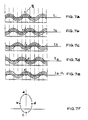
- each segment executes contractions and extensions with the period of the AC voltage, so that, as illustrated in FIG. 5d, standing waves form in the oscillating stator.
- FIGS. 6a-6e show the generation of traveling waves on the surface 7 of a vibration stator 5 by superimposing standing waves, which are each generated in two piezo systems 6A and 6B offset by ⁇ / 4 wavelength. While FIG. 6a shows the configuration of the piezoceramics 6A and 6B of the vibration stator 5, FIGS. 6b-6e illustrate the superimposition A and B of the vibration states A generated by the sine and cosine excitations (FIG. 6b) for different times T0, T1, T2 , B the surface 7 of the stator.
- the contact surface is reduced when excitation of traveling waves in the vibrating body to the range of the vibration maxima of the traveling waves, whereby the rotor coupled to the stator surface by friction corresponds to the movement of the surface points along their elliptical Path that performs a movement opposite to the direction of propagation of the traveling wave.
- a disadvantage of the known ultrasonic traveling wave motors is that they always work with only a certain fixed waveform of the traveling waves, in particular a fixed number of straight lines and circles of nodes, namely only zero or one node circle.
- the present invention is based on the knowledge that in the stator of an ultrasonic motor different vibration modes - in the case of a rotationally symmetrical stator classifiable according to the number of straight lines and knot circles - can be excited and used to influence dynamic properties such as rotational speed or torque.
- the knowledge is used that with suitable excitation systems in a rotationally symmetrical stator, wave modes with different node lines are excited, and that the position of the contact zone between the stator and rotor surfaces changes with a variation in the number of node circles, and thus dynamic variables such as the speed of rotation are varied over very wide ranges can.
- the object of the present invention is to provide a method for operating an ultrasound motor with different traveling wave modes and an ultrasound traveling wave motor with several transmission ratios.
- FIGS. 8a-8c show cross-sectional representations of an ultrasonic motor according to the invention, which works with three gear ratios.
- the disc-shaped rotor 8 has three annular ridges 9, 10 and 11 with the respective radii r1, r2 and r3.
- the stator 12 which is only shown schematically as a plate in the figure, traveling waves with different numbers of node circles are excited.
- a fashion without a knot circle is shown in radial section in FIG. 8a.
- the maximum deflection R (r 1) of the stator 12 takes place at the edge at a radial distance r 1 from the center of the disk, so that the rotor and stator are essentially in contact only in the region of the elevation 9.
- FIG. 8b shows the motor when a mode is initiated with a node circle.
- the maximum stator deflection and the contact between the stator and rotor takes place here in the range of the radial distance r2.
- the motor is shown in Figure 8c when a mode with two node circles and a contact surface between the rotor and stator in the region of the radial distance r3 is excited.
- the contact radii r1, r2 and r3 between the rotor and stator are determined by the modes and natural frequencies of the stator.
- the motor is generally operated with an external excitation frequency close to a natural frequency of the free stator. By transition from an excitation frequency ⁇ 1 to a frequency ⁇ 2, a transition from a translation stage with contact radius r1 to a second stage with radius r2 is effected.
- the stator has in the area of the maximum vibration deflections, e.g. B. r1, r2 and r3 increases, for. B. in the form of teeth.
- the circular layers 12 and 13 can be connected in planes one above the other and connected to one another by an elastic intermediate layer, or can be arranged concentrically to one another in a common plane.
- the motor is operated in a mode with a desired number of straight lines in that the respective ceramic layer is controlled via its working electrodes, while the other layer remains passive.
- Another embodiment of the motor according to the invention which works with traveling wave modes with different numbers of straight lines and knot circles, consists of a combination of the embodiments shown in FIGS. 8 and 9.
- the desired operating mode in this embodiment results from the fact that in each case the ceramic layer corresponding to the desired number of node lines is driven with the frequency ⁇ corresponding to the desired contact radius or number of node circles.
- FIGS. 10 and 11 show the sectional view of a circular disc element of height h with glued-on piezoceramic edge layer 9 and thickness e.
- the forces and moments acting in the surface element 14 under the boundary layer 15 are shown in FIG. 11, polar coordinates r, ⁇ being chosen because of the circular symmetry.
- the shear stresses in the bond are with ⁇ , the lateral force per unit length with Q, the moment per unit length with M and the normal stress with ⁇ .
- the equation of motion must be supplemented by terms that take into account the damping introduced by the energy transport to the rotor.
- the above-mentioned formula for the angular velocity ⁇ R can then be obtained under the condition of a slip-free contact between the rotor and the stator surface with external excitation in the vicinity of the natural frequencies (proximity to resonance) by a positive excitation of the shape q (r, ⁇ , t) ⁇ [cos n ⁇ cos ⁇ t + sin n ⁇ sin ⁇ t] R ⁇ (r).
- FIG. 13 shows the radial section of a vibration form obtained from a numerical solution of the equation of motion with nine straight lines for the dimensionless natural frequencies a: 77.62, b: 133.65 and c: 193.09 and zero or one or two knot circles.
- the dimensionless natural frequencies must be multiplied by a factor depending on the dimensions of the stator and the material.
Landscapes
- General Electrical Machinery Utilizing Piezoelectricity, Electrostriction Or Magnetostriction (AREA)
Claims (9)
- Procédé pour faire fonctionner un moteur à ultrasons, comprenant un stator fait d'un matériau élastique et présentant un ou plusieurs oscillateurs à ultrasons pour exciter des ondes progressives, de même qu'un rotor, procédé dans lequel le stator et le rotor sont en contact l'un avec l'autre, sous une pression, dans une zone de surface, caractérisé en ce que, pour l'entraînement du rotor avec plusieurs étages de rapports de transmission, des modes d'ondes progressives de différentes formes de vibration sont excités.
- Procédé selon la revendication 1, caractérisé en ce que, pour l'entraînement du rotor, des modes d'ondes progressives, ayant un nombre fixe de droites nodales et un nombre variable de cercles nodaux, sont excités dans la surface du stator.
- Procédé selon la revendication 1, caractérisé en ce que, pour l'entraînement du rotor, des modes d'ondes progressives, ayant un nombre fixe de cercles nodaux et un nombre variable de droites nodales, sont excités dans la surface du stator.
- Procédé selon la revendication 1, caractérisé en ce que, pour l'entraînement du rotor, des modes d'ondes progressives, ayant un nombre variable de droites nodales et un nombre variable de cercles nodaux, sont excités dans la surface du stator.
- Procédé selon la revendication 3 ou 4, caractérisé en ce que plusieurs oscillateurs à ultrasons sont prévus, chaque oscillateur excitant des modes d'ondes progressives ayant chaque fois un nombre fixe de droites nodales.
- Moteur à ultrasons, comprenant un stator fait d'un matériau élastique et présentant un ou plusieurs oscillateurs à ultrasons pour exciter des ondes progressives, de même qu'un rotor, le stator et le rotor étant en contact l'un avec l'autre, sous pression, dans une zone de surface, caractérisé en ce que, pour l'entraînement du rotor avec plusieurs étages de rapports de transmission dans la région de la déviation ou du déplacement de vibration maximal de différents modes d'ondes progressives susceptibles d'être excités, des zones surélévées sont prévues en tant que faces de contact dans la surface du rotor ou du stator.
- Moteur à ultrasons selon la revendication 6, caractérisé en ce que les oscillateurs à ultrasons sont réalisés sous la forme de disques et sont superposés à la façon de coucbes en étant reliés entre eux par des couches intermédiaires élastiques.
- Moteur à ultrasons selon la revendication 6 ou 7, caractérisé en ce que les oscillateurs à ultrasons sont disposés concentriquement l'un par rapport à l'autre.
- Moteur à ultrasons selon la revendication 8, caractérisé en ce que les zones surélevées de la surface du rotor ou du stator sont en forme de couronne circulaire.
Applications Claiming Priority (2)
| Application Number | Priority Date | Filing Date | Title |
|---|---|---|---|
| DE3927040A DE3927040A1 (de) | 1989-08-16 | 1989-08-16 | Ultraschall wanderwellenmotor mit zwei oder mehr stufen |
| DE3927040 | 1989-08-16 |
Publications (2)
| Publication Number | Publication Date |
|---|---|
| EP0413111A1 EP0413111A1 (fr) | 1991-02-20 |
| EP0413111B1 true EP0413111B1 (fr) | 1994-07-13 |
Family
ID=6387223
Family Applications (1)
| Application Number | Title | Priority Date | Filing Date |
|---|---|---|---|
| EP90111985A Expired - Lifetime EP0413111B1 (fr) | 1989-08-16 | 1990-06-25 | Moteur à onde progressive ultra-sonore à deux ou plusieurs plots |
Country Status (5)
| Country | Link |
|---|---|
| EP (1) | EP0413111B1 (fr) |
| AT (1) | ATE108579T1 (fr) |
| DE (2) | DE3927040A1 (fr) |
| DK (1) | DK0413111T3 (fr) |
| ES (1) | ES2057280T3 (fr) |
Families Citing this family (5)
| Publication number | Priority date | Publication date | Assignee | Title |
|---|---|---|---|---|
| DE4216273C2 (de) * | 1992-05-16 | 1996-06-05 | Daimler Benz Ag | Wanderwellenmotor zum Betrieb mit unterschiedlichen Schwingungsformen |
| DE4243323C2 (de) * | 1992-12-21 | 1996-10-02 | Daimler Benz Ag | Schwingungsmotor mit Resonanzvermeidung |
| JP3804973B2 (ja) * | 1994-10-31 | 2006-08-02 | ペーイー セラミック ゲーエムベーハー | 圧電モーター |
| DE4446606A1 (de) * | 1994-12-28 | 1996-07-04 | Wilo Gmbh | Piezo-Wanderwellenmotor |
| CN103684036A (zh) * | 2012-09-18 | 2014-03-26 | 精工爱普生株式会社 | 压电马达、机器人手、机器人、电子部件搬运装置、电子部件检查装置、送液泵、打印装置 |
Family Cites Families (1)
| Publication number | Priority date | Publication date | Assignee | Title |
|---|---|---|---|---|
| US4786836A (en) * | 1984-03-01 | 1988-11-22 | Matsushita Electric Industrail Co., Ltd. | Piezoelectric motor |
-
1989
- 1989-08-16 DE DE3927040A patent/DE3927040A1/de not_active Withdrawn
-
1990
- 1990-06-25 DE DE59006409T patent/DE59006409D1/de not_active Expired - Fee Related
- 1990-06-25 AT AT90111985T patent/ATE108579T1/de active
- 1990-06-25 EP EP90111985A patent/EP0413111B1/fr not_active Expired - Lifetime
- 1990-06-25 ES ES90111985T patent/ES2057280T3/es not_active Expired - Lifetime
- 1990-06-25 DK DK90111985.9T patent/DK0413111T3/da active
Non-Patent Citations (1)
| Title |
|---|
| IEEE 1987 ULTRASONICS SYMPOSIUM PROCEEDINGS vol. 2, 14. Oktober 1987, Denver, Colorado, Seiten 747-756 ; R. INABA et al. : "Piezoelectric Ultrasonic Motor" * |
Also Published As
| Publication number | Publication date |
|---|---|
| DE3927040A1 (de) | 1991-02-21 |
| DK0413111T3 (da) | 1994-07-13 |
| ES2057280T3 (es) | 1994-10-16 |
| DE59006409D1 (de) | 1994-08-18 |
| ATE108579T1 (de) | 1994-07-15 |
| EP0413111A1 (fr) | 1991-02-20 |
Similar Documents
| Publication | Publication Date | Title |
|---|---|---|
| DE3587940T2 (de) | Piezoelektrischer Motor. | |
| EP1267425B1 (fr) | Elément de positionnement piézoélectrique | |
| DE3415628C3 (de) | Vibrationswellenmotor | |
| DE102010022812B4 (de) | Ultraschallmotor | |
| EP0789937B1 (fr) | Moteur piezo-electrique | |
| EP1747594B1 (fr) | Moteur a ultrasons piezo-electrique | |
| DE3852258T2 (de) | Piezoelektrischer Motor. | |
| DE3423884C2 (fr) | ||
| DE3415630A1 (de) | Vibrationswellenmotor | |
| EP2845305B1 (fr) | Moteur à ultrasons | |
| EP0569673B1 (fr) | Moteur ultrasonique à ondes progressives entraîné par des organes d'actionnement attachés par liaison de forme | |
| DE102013110356B4 (de) | Ultraschallaktor | |
| EP0413111B1 (fr) | Moteur à onde progressive ultra-sonore à deux ou plusieurs plots | |
| DE102004044184B4 (de) | Miniaturisierbarer Motor | |
| DE69130751T2 (de) | Vibrationsangetriebener Motor | |
| EP1396012B2 (fr) | Entrainement piezoelectrique | |
| EP2608286A2 (fr) | Actionneur à ultrasons | |
| WO2004064170A2 (fr) | Procede pour faire fonctionner un moteur piezo-electrique et moteur piezo-electrique comprenant un stator qui se presente sous la forme d'un oscillateur cylindrique creux | |
| DE4305894C1 (de) | Schwingungsanregung bei einem Schwingungsmotor mit zylinderförmigem Schwingkörper | |
| EP0570673B1 (fr) | Moteur à ondes progressives fonctionnant en modes de vibrations différents | |
| DE4244704C2 (de) | Wanderwellenmotor mit zylinderförmigem Schwingkörper | |
| DE4243323C2 (de) | Schwingungsmotor mit Resonanzvermeidung | |
| DE102020130013B3 (de) | Ultraschallaktor | |
| DE102022114863B3 (de) | Ultraschallmotor | |
| WO1991011850A1 (fr) | Moteur ultrasonique avec deux rotors |
Legal Events
| Date | Code | Title | Description |
|---|---|---|---|
| PUAI | Public reference made under article 153(3) epc to a published international application that has entered the european phase |
Free format text: ORIGINAL CODE: 0009012 |
|
| AK | Designated contracting states |
Kind code of ref document: A1 Designated state(s): AT BE CH DE DK ES FR GB GR IT LI LU NL SE |
|
| 17P | Request for examination filed |
Effective date: 19910220 |
|
| 17Q | First examination report despatched |
Effective date: 19930507 |
|
| GRAA | (expected) grant |
Free format text: ORIGINAL CODE: 0009210 |
|
| AK | Designated contracting states |
Kind code of ref document: B1 Designated state(s): AT BE CH DE DK ES FR GB GR IT LI LU NL SE |
|
| PG25 | Lapsed in a contracting state [announced via postgrant information from national office to epo] |
Ref country code: NL Effective date: 19940713 Ref country code: GR Free format text: LAPSE BECAUSE OF FAILURE TO SUBMIT A TRANSLATION OF THE DESCRIPTION OR TO PAY THE FEE WITHIN THE PRESCRIBED TIME-LIMIT Effective date: 19940713 Ref country code: BE Effective date: 19940713 |
|
| REF | Corresponds to: |
Ref document number: 108579 Country of ref document: AT Date of ref document: 19940715 Kind code of ref document: T |
|
| REF | Corresponds to: |
Ref document number: 59006409 Country of ref document: DE Date of ref document: 19940818 |
|
| ITF | It: translation for a ep patent filed | ||
| PG25 | Lapsed in a contracting state [announced via postgrant information from national office to epo] |
Ref country code: SE Effective date: 19941013 |
|
| REG | Reference to a national code |
Ref country code: ES Ref legal event code: FG2A Ref document number: 2057280 Country of ref document: ES Kind code of ref document: T3 |
|
| ET | Fr: translation filed | ||
| GBT | Gb: translation of ep patent filed (gb section 77(6)(a)/1977) |
Effective date: 19941013 |
|
| NLV1 | Nl: lapsed or annulled due to failure to fulfill the requirements of art. 29p and 29m of the patents act | ||
| PGFP | Annual fee paid to national office [announced via postgrant information from national office to epo] |
Ref country code: GB Payment date: 19950517 Year of fee payment: 6 |
|
| PLBE | No opposition filed within time limit |
Free format text: ORIGINAL CODE: 0009261 |
|
| STAA | Information on the status of an ep patent application or granted ep patent |
Free format text: STATUS: NO OPPOSITION FILED WITHIN TIME LIMIT |
|
| PGFP | Annual fee paid to national office [announced via postgrant information from national office to epo] |
Ref country code: FR Payment date: 19950602 Year of fee payment: 6 |
|
| PGFP | Annual fee paid to national office [announced via postgrant information from national office to epo] |
Ref country code: ES Payment date: 19950621 Year of fee payment: 6 |
|
| PG25 | Lapsed in a contracting state [announced via postgrant information from national office to epo] |
Ref country code: DK Effective date: 19950625 Ref country code: AT Effective date: 19950625 |
|
| PG25 | Lapsed in a contracting state [announced via postgrant information from national office to epo] |
Ref country code: LU Free format text: LAPSE BECAUSE OF NON-PAYMENT OF DUE FEES Effective date: 19950630 |
|
| 26N | No opposition filed | ||
| PGFP | Annual fee paid to national office [announced via postgrant information from national office to epo] |
Ref country code: CH Payment date: 19950808 Year of fee payment: 6 |
|
| PG25 | Lapsed in a contracting state [announced via postgrant information from national office to epo] |
Ref country code: GB Effective date: 19960625 |
|
| PG25 | Lapsed in a contracting state [announced via postgrant information from national office to epo] |
Ref country code: ES Free format text: LAPSE BECAUSE OF THE APPLICANT RENOUNCES Effective date: 19960626 |
|
| PG25 | Lapsed in a contracting state [announced via postgrant information from national office to epo] |
Ref country code: LI Effective date: 19960630 Ref country code: CH Effective date: 19960630 |
|
| GBPC | Gb: european patent ceased through non-payment of renewal fee |
Effective date: 19960625 |
|
| REG | Reference to a national code |
Ref country code: CH Ref legal event code: PL |
|
| PG25 | Lapsed in a contracting state [announced via postgrant information from national office to epo] |
Ref country code: FR Effective date: 19970228 |
|
| REG | Reference to a national code |
Ref country code: FR Ref legal event code: ST |
|
| REG | Reference to a national code |
Ref country code: ES Ref legal event code: FD2A Effective date: 19991007 |
|
| PGFP | Annual fee paid to national office [announced via postgrant information from national office to epo] |
Ref country code: DE Payment date: 20050613 Year of fee payment: 16 |
|
| PG25 | Lapsed in a contracting state [announced via postgrant information from national office to epo] |
Ref country code: IT Free format text: LAPSE BECAUSE OF NON-PAYMENT OF DUE FEES Effective date: 20050625 |
|
| PG25 | Lapsed in a contracting state [announced via postgrant information from national office to epo] |
Ref country code: DE Free format text: LAPSE BECAUSE OF NON-PAYMENT OF DUE FEES Effective date: 20070103 |