EP0412660B1 - Heat-insulating piston - Google Patents
Heat-insulating piston Download PDFInfo
- Publication number
- EP0412660B1 EP0412660B1 EP19900307647 EP90307647A EP0412660B1 EP 0412660 B1 EP0412660 B1 EP 0412660B1 EP 19900307647 EP19900307647 EP 19900307647 EP 90307647 A EP90307647 A EP 90307647A EP 0412660 B1 EP0412660 B1 EP 0412660B1
- Authority
- EP
- European Patent Office
- Prior art keywords
- heat
- insulating
- piston
- piston head
- head base
- Prior art date
- Legal status (The legal status is an assumption and is not a legal conclusion. Google has not performed a legal analysis and makes no representation as to the accuracy of the status listed.)
- Expired - Lifetime
Links
Images


Classifications
-
- F—MECHANICAL ENGINEERING; LIGHTING; HEATING; WEAPONS; BLASTING
- F02—COMBUSTION ENGINES; HOT-GAS OR COMBUSTION-PRODUCT ENGINE PLANTS
- F02F—CYLINDERS, PISTONS OR CASINGS, FOR COMBUSTION ENGINES; ARRANGEMENTS OF SEALINGS IN COMBUSTION ENGINES
- F02F3/00—Pistons
- F02F3/0015—Multi-part pistons
- F02F3/003—Multi-part pistons the parts being connected by casting, brazing, welding or clamping
-
- F—MECHANICAL ENGINEERING; LIGHTING; HEATING; WEAPONS; BLASTING
- F02—COMBUSTION ENGINES; HOT-GAS OR COMBUSTION-PRODUCT ENGINE PLANTS
- F02F—CYLINDERS, PISTONS OR CASINGS, FOR COMBUSTION ENGINES; ARRANGEMENTS OF SEALINGS IN COMBUSTION ENGINES
- F02F3/00—Pistons
- F02F3/10—Pistons having surface coverings
- F02F3/12—Pistons having surface coverings on piston heads
-
- F—MECHANICAL ENGINEERING; LIGHTING; HEATING; WEAPONS; BLASTING
- F05—INDEXING SCHEMES RELATING TO ENGINES OR PUMPS IN VARIOUS SUBCLASSES OF CLASSES F01-F04
- F05C—INDEXING SCHEME RELATING TO MATERIALS, MATERIAL PROPERTIES OR MATERIAL CHARACTERISTICS FOR MACHINES, ENGINES OR PUMPS OTHER THAN NON-POSITIVE-DISPLACEMENT MACHINES OR ENGINES
- F05C2251/00—Material properties
- F05C2251/04—Thermal properties
- F05C2251/042—Expansivity
-
- F—MECHANICAL ENGINEERING; LIGHTING; HEATING; WEAPONS; BLASTING
- F05—INDEXING SCHEMES RELATING TO ENGINES OR PUMPS IN VARIOUS SUBCLASSES OF CLASSES F01-F04
- F05C—INDEXING SCHEME RELATING TO MATERIALS, MATERIAL PROPERTIES OR MATERIAL CHARACTERISTICS FOR MACHINES, ENGINES OR PUMPS OTHER THAN NON-POSITIVE-DISPLACEMENT MACHINES OR ENGINES
- F05C2253/00—Other material characteristics; Treatment of material
- F05C2253/16—Fibres
Definitions
- the present invention relates to a heat-insulating piston for a heat-insulating engine.
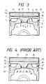
- FIG. 4 A conventional heat-insulating piston as shown in Fig. 4 has been disclosed.
- a mounting boss portion 28 formed at the center of a heat base portion 21 is fitted into a mounting hole 31 formed in the center of a piston skirt portion 22, and the two members are fixed together by means of a metal flow 29.
- a stepped portion 32 is formed on the inner circumferential surface of a ring portion 24 that constitutes the upper portion of the sliding surface of a piston, and the head base portion 21 is locked onto this stepped portion 32 at the outer circumferential portion 33 thereof.
- the ring portion 24 is fixed to the piston skirt portion 22 in a pressed state via a sealing member 27.
- a heat-insulating layer 23 is provided in the cylindrical bore portion constituted by the head base portion 21 and ring portion 24, and a thin plate 25 formed of a ceramic material is placed on the surface of the heat-insulating layer 23 that faces a combustion chamber.
- reference numeral 26 denotes a layer of heat-insulating air.
- a heat-insulating piston having a structure similar to the above-described one is disclosed in the specification of U.S. Patent No. 4848291 (refer to the official gazette of Japanese Patent Laid-Open No. 302164/1988) filed by the applicant of the present invention.
- the structure of the heat-insulating piston so disclosed will be briefly described with reference to Fig. 5.
- the piston comprises a piston head 41 having at its central portion a boss 44 and formed of a material having a coefficient of thermal expansion substantially equal to that of a ceramic material, and a metallic piston skirt 42 having at its central portion a mounting hole 52 into which the mounting boss 44 is fitted.
- the mounting boss 44 of the piston head 41 is set fixedly in the central mounting hole 52 in the piston skirt 42 by means of a metal ring 51 as a metal flow.
- a buffer member 48 consisting of a heat-insulating gasket is inserted in a pressed stage between the piston heat 41 and piston skirt 42 at the central portion where the two members are brought into contact with each other.
- a layer 49 of heat-insulating air is also formed between the piston head 41 and piston skirt 42.
- a thin plate portion 45 of a ceramic material which is formed to an extremely small thickness so as to reduce the thermal capacity of the surface of the heat-insulating piston is provided on the piston head 41 via a heat-insulating member 43 so that the thin plate portion faces the combustion chamber.
- a ceramic ring 46 the material of which is the same as that of the ceramic thin plate portion 45 is fitted around the outer circumferential portion of the thin plate portion 45, and the ceramic thin plate portion 45 and ceramic ring 46 are joined to each other at a contact portion by chemical vapor deposition.
- a stepped portion 56 is formed on the inner circumferential surface of the ceramic ring 46, and the outer circumferential portion of the piston head 41 is fitted in the ceramic ring 46 so as to contact the stepped portion 56 of the ring 46.
- the heat-insulating member 43 is sealed in a space defined by the ceramic thin plate portion 45, ceramic ring 46 and piston head 41, and this heat-insulating member 43 consists of whiskers of potassium titanate, zirconia fiber or the like. Since the piston head 41 is set in a pushed state in the piston skirt 42, the outer circumferential portion of the piston head 41 is pressed against the stepped portion 56 of the ceramic ring 46, and the ceramic ring 46 against the circumferential portion of the piston skirt 42. A gasket consisting of a carbon seal 47 for ensuring sealing between the ceramic ring 46 and piston skirt 42 is inserted therebetween.
- a heat-insulating engine member such as a piston that utilizes a ceramic material as a heat-insulating or heat-resisting material. Since the ceramic material is exposed to the high temperature heat in the combustion chamber, it receives a thermal shock. Therefore, it is necessary that the member consisting of a ceramic material be formed to a preferable strength. If the thickness of the ceramic material constituting the wall is increased for the heat-insulating purpose, the thermal capacity of the wall becomes large. Accordingly, in a suction stroke, the suction air receives a large quantity of heat from the combustion chamber to cause the temperature of the suction air to increase, so that this heat adversely affects the air suction operation. As a result, the suction efficiency decreases, and the air suction operation stops. In contrast, in an expansion stroke, the heat-insulating characteristics must be improved.
- the heat-insulating piston structure disclosed in the afore-mentioned U.S. Patent No. 4848291 and constructed as above to solve these problems, has excellent heat-insulating characteristics, can set to the lowest possible level the thermal capacity of the surface member of the piston head which faces the combustion chamber the temperature in which becomes high due to combustion gas to which the combustion chamber is exposed, can improve suction and cycle efficiencies, and does not give rise to a problem of strength of the surface of the piston head even when it receives a thermal shock.
- thermal resistance, corrosion resistance and deformation resistance can be improved, and stable mounting can be ensured.
- the pressure applied to the piston head during an explosion stroke can be received in a preferable condition, whereby an improved sealing capability can be ensured between the piston head and piston skirt.
- the heat-insulating material interposed between the piston head base portion and the ceramic thin plate portion placed on the side of the combustion chamber consists of whiskers or fibers of mullite, alumina, potassium titanate, zirconia or the like, while the ceramic thin plate portion and ceramic ring consist of silicon nitride.
- This difference in the constituent of the relevant members causes the following drawback. Since the materials used for the heat-insulating material and the ceramic thin plate portion and ceramic ring that surround the heat-insulating material are different, there will be a difference in the thermal expansion between the heat-insulating material and the surrounding ceramic thin plate portion and ceramic ring as the temperature changes.
- An object of the present invention is to provide a heat-insulating piston capable of solving the afore-mentioned problems in which not only an extremely high heat-insulating capability is ensured at the piston head portion but a heat-resisting capability is also ensured at the surface portion of the piston head that faces the combustion chamber the temperature in which becomes high due to exposure to combustion gas,with the thermal capacity of the surface portion being made as low as possible so that the surface portion can follow the change in the temperature of combustion gas, whereby the suction efficiency can be improved.
- a heat-insulating piston comprising: a piston skirt having an upper circumferential end portion and a mounting hole formed therein; a piston head base portion having a mounting boss portion fitted in said mounting hole such that a lower circumferential end portion of said piston head base portion is fixed in a pressed state to said upper circumferential end portion of said piston skirt, said piston head base portion being formed of ceramic material; a heat-insulating member fixed to said piston head base portion consisting of a whisker fired member of a ceramic material; and a laminate joined to a surface of said heat-insulating member in use exposed to a combustion gas, and consisting of a ceramic material; characterised in that said piston head base portion, said heat-insulating member and said laminate are formed out of the same ceramic material.
- the surface portion can be formed as a laminate using a ceramic material such as silicon nitride (Si3N4), silicon carbide (SiC) or the like, with the heat-insulating member consisting of the same ceramic material of fired whiskers as that used for the laminate and the piston head base portion.
- the heat-insulating member can then be stably joined to the laminate and piston head base portion, so that a sufficient strength and reliability can be ensured for the piston.
- the heat-insulating member an extremely high heat insulating capability can be obtained by the heat-insulating member, and the thickness of the laminate disposed on the surface of the piston head portion that is heated to a high temperature due to its exposure to combustion gas can be made as small as possible, while the thermal capacity thereof is made as low as possible. Consequently, the suction efficiency can be improved, and high resistance to heat, deformation and corrosion can be obtained by this laminate.
- said piston head base portion has an annular portion integrally formed therewith out of a ceramic material to form a sliding surface extending upwardly from the circumference of said piston head base portion, being formed out of the same kind of ceramic material as said piston head base portion, said heat-insulating member and said laminate, and said heat-insulating member is provided in a cylindrical bore portion defined by said annular portion, and joined to the upper surface of said piston head base portion.
- the heat-insulating member may be accommodated in the piston head base portion particularly securely and stably.
- said piston head base portion has an annular portion integrally formed therewith out of a ceramic material so as to form a sliding surface extending upwardly from the circumference of said piston head base portion, said annular portion being formed out of the same kind of ceramic material as said piston head base portion, said heat-unsulating member and said laminate, said heat-insulating member being provided in a cylindrical bore portion defined by said annular portion, and joined to the inner circumferential surface of said annular portion.
- the heat-insulating portion may be joined to the piston head base portion only at the inner circumferential surface of the annular portion.
- the heat-insulating member may also be accommodated in the piston head base portion particularly securely and stably.
- the heat-insulating member may be stably jointed to the piston head base portion at the circumferential surface thereof. Since the lower surface of the heat-insulating member and the upper surface of the piston head base portion is made free relative to each other, even if a large tensile force is caused to act between the heat-insulating member and the piston head base portion, the jointed state between these two members is prevented from being adversely affected, and hence the stable joint therebetween may be maintained. Moreover, the jointed state between the laminate and the heat-insulating member is also prevented from being adversely affected. Thus, it is possible to prevent a risk of any cracks or damages occurring in the heat-insulating member and the laminate, even if a tensile force is caused to act thereon.
- Fig. 1 is a vertical cross-sectional view of an embodiment of the heat-insulating piston according to the present invention.
- This heat-insulating piston comprises a piston head and a metallic piston skirt 2.
- this piston head comprises a piston head base portion 1, a heat-insulating member and a laminate 5.
- the piston head base portion 1 consists of a ceramic material such as silicon nitride (Si3N4), silicon carbide (SiC) or the like, and has at its central portion a mounting boss portion 8. There is no combustion chamber formed in the piston head base portion 1, and the side of this piston head base portion 1 that faces a combustion chamber is formed flat.
- a central mounting hole 12 Formed in the central portion of the piston skirt 2 is a central mounting hole 12 into which the mounting boss portion 8 of the piston head base portion 1 is fitted.
- the mounting boss portion 8 of this piston head base portion 1 is fitted in the central mounting hole 12 of the piston skirt 2, and a metal ring 9 is inserted in a deformed state in fitting grooves formed in the mounting boss portion 8 and the central mounting hole 12 of the piston skirt 2, respectively, by utilizing the metal flow thereof, whereby the piston head base portion 1 is locked to the piston skirt 2 in a pressed state.
- a sealing member 7 is interposed in a pressed state at a position where the circumferential bottom surface of the piston head base portion 1 and the circumferential top surface of the piston skirt 2 are brought into contact with each other.
- a layer of heat-insulating air 6 is formed between the piston head base portion 1 and the piston skirt 2.
- the heat-insulating piston according to the present invention having a structure as described above has the following characteristics. Namely, this heat-insulating piston has the heat-insulating member 3 for constituting a heat-insulating layer jointed to the piston head base portion 1 and consisting of a whisker fired member of the same ceramic material as that of the piston head base portion 1, and a laminate 5 jointed to the surface of the heat-insulating member 3 that faces the combustion chamber, i.e. the surface 10 that is exposed to combustion gas, as well as to the surface 11 of the same that slides over a cylinder liner (not shown) and consisting of the same ceramic material as that of the heat-insulating member 3.
- the heat-insulating member 3 consists of a whisker fired member of a ceramic material such as silicon nitride (Si3N4), silicon carbide (SiC) or the like, and this whisker fired member is jointed to the top surface 4 of the piston head base portion 1 consisting of the same ceramic material as its own ceramic material.
- the laminate 5 disposed on the outer surface of the heat-insulating member 3 also consists of a ceramic material such as similar silicon nitride (Si3N4), silicon carbide (SiC) or the like, and is disposed so as to be jointed to the surface of the heat-insulating member 3 that is exposed to combustion gas, i.e. the surface 10 that faces the combustion chamber and the surface 11 of the same member 3 that slides relative to the cylinder liner by virtue of chemical vapor deposition or coating.
- this laminate 5 constitutes not only the surface that is exposed to combustion gas but also the surface sliding relative to the cylinder liner. Moreover, the laminate is formed to an extremely small thickness. Thus, the thermal capacity of the surface that is exposed to combustion gas may be reduced to a low level with a sufficient heat-insulating capability being ensured.
- the heat-insulating member 3 constituted by a whisker fired member of a ceramic such as silicon nitride (Si3N4), silicon carbide (SiC) or the like may function not only as a heat insulator but also as a structure member for receiving a pressure acting on the laminate 5 in an explosion stroke. In this heat-insulating piston, a compressive force generated in an explosion stroke needs to be received by the heat-insulating member 3 in a uniform fashion, and in order to make this possible, the top surface 4 of the piston head base portion 1 and the laminate 5 are formed flat.
- FIG. 2 another embodiment of the heat-insulating piston in accordance with the present invention will be described below.
- the structure and functions of the heat-insulating piston according to this embodiment are similar to those of the heat-insulating piston described above except that the configuration of the piston head base portions 1 of the respective piston head base portions are slightly different from each other. Therefore, like reference numerals are given to like constituent members, and similar descriptions will be omitted.
- the piston head base portion 1 is mounted on the piston skirt 2, but in this case, the piston head base portion 1 has a sliding surface 13 upwardly extending to the top end surface of the piston head.
- the piston head base portion 1 has an integral thin annular portion 15 at its circumferential top end portion, and therefore a cylindrical bore portion 14 surrounded by the annular portion 15, i.e. a thin wall portion, is formed on the side that faces the combustion chamber.
- the heat-insulating member 3 consisting of a whisker fired member or a ceramic material such as silicon nitride (Si3N4), silicon carbide (SiC) or the like that is the same as that of the cylindrical portion 15 is disposed in the cylindrical bore portion 14 constituted by this cylindrical portion 15 so as to form a heat-insulating layer.
- This heat-insulating member 3 is jointed to the bottom of the cylindrical bore portion 14, i.e.
- a ceramic material such as silicon nitride (Si3N4), silicon carbide (SiC) or the like
- FIG. 3 a further embodiment of the heat-insulating piston in accordance with the present invention will now be described. Since the structure and functions of the heat-insulating piston of this embodiment are the same as those of the heat-insulating piston shown in Fig. 2 except that the position where the heat-insulating member is jointed is slightly different from each other, like reference numerals are given to like constituent members, and similar descriptions will be omitted.
- the heat-insulating member 3 is jointed to the piston head base portion 1 at the inner circumferential surface, i.e. a joint portion 16, of the annular portion 15 formed in the piston head base portion 1.
- the sealing member 7 is interposed between the outer circumferential bottom end surface of the piston head base portion 1 and the outer circumferential top end surface of the piston skirt 2, and in order to ensure good sealing state by the sealing member 7, a force is caused to downwardly act on the mounting boss portion 8 formed in the central portion of the piston head base portion 1, and a gap 17 develops between the upper surface 4 of the piston head base portion 1 and the lower surface 18 of the heat-insulating member 3.
- this gap 17 is exaggerated, and in reality the gap is so narrow that it cannot be recognized visually.
- the joint portion 16 coincides with the outer circumferential portion of the heat-insulating member 3, even if a downward force is caused to act on the mounting boss portion 8 so as to cause a gap, any force for separating the joint portion 16 from the heat-insulating member 3 is prevented from acting on the relevant members due to the urging force generated by sealing the heat-insulating member 3 in the cylindrical bore portion 14.
- the joint portion 16 is prevented from being adversely affected due to the generation of a gap, and the stable jointed state between the piston head base portion 1 and the heat-insulating member 3 may be maintained.
- the jointed state between the heat-insulating member 3 and the laminate 5 jointed to the top surface 10 of the same member by virtue of chemical vapor deposition, coating or the like is prevented from being adversely affected.
Description
- The present invention relates to a heat-insulating piston for a heat-insulating engine.
- A conventional heat-insulating piston as shown in Fig. 4 has been disclosed. In Fig. 4, a
mounting boss portion 28 formed at the center of aheat base portion 21 is fitted into amounting hole 31 formed in the center of apiston skirt portion 22, and the two members are fixed together by means of ametal flow 29. In this example, astepped portion 32 is formed on the inner circumferential surface of aring portion 24 that constitutes the upper portion of the sliding surface of a piston, and thehead base portion 21 is locked onto thisstepped portion 32 at the outercircumferential portion 33 thereof. In addition, thering portion 24 is fixed to thepiston skirt portion 22 in a pressed state via a sealingmember 27. Furthermore, a heat-insulatinglayer 23 is provided in the cylindrical bore portion constituted by thehead base portion 21 andring portion 24, and athin plate 25 formed of a ceramic material is placed on the surface of the heat-insulatinglayer 23 that faces a combustion chamber. In Fig. 4,reference numeral 26 denotes a layer of heat-insulating air. - A heat-insulating piston having a structure similar to the above-described one is disclosed in the specification of U.S. Patent No. 4848291 (refer to the official gazette of Japanese Patent Laid-Open No. 302164/1988) filed by the applicant of the present invention. The structure of the heat-insulating piston so disclosed will be briefly described with reference to Fig. 5. The piston comprises a
piston head 41 having at its central portion aboss 44 and formed of a material having a coefficient of thermal expansion substantially equal to that of a ceramic material, and ametallic piston skirt 42 having at its central portion amounting hole 52 into which themounting boss 44 is fitted. In addition, themounting boss 44 of thepiston head 41 is set fixedly in thecentral mounting hole 52 in thepiston skirt 42 by means of ametal ring 51 as a metal flow. - A
buffer member 48 consisting of a heat-insulating gasket is inserted in a pressed stage between thepiston heat 41 andpiston skirt 42 at the central portion where the two members are brought into contact with each other. In addition, alayer 49 of heat-insulating air is also formed between thepiston head 41 andpiston skirt 42. Athin plate portion 45 of a ceramic material which is formed to an extremely small thickness so as to reduce the thermal capacity of the surface of the heat-insulating piston is provided on thepiston head 41 via a heat-insulatingmember 43 so that the thin plate portion faces the combustion chamber. Aceramic ring 46, the material of which is the same as that of the ceramicthin plate portion 45 is fitted around the outer circumferential portion of thethin plate portion 45, and the ceramicthin plate portion 45 andceramic ring 46 are joined to each other at a contact portion by chemical vapor deposition. - A
stepped portion 56 is formed on the inner circumferential surface of theceramic ring 46, and the outer circumferential portion of thepiston head 41 is fitted in theceramic ring 46 so as to contact thestepped portion 56 of thering 46. The heat-insulatingmember 43 is sealed in a space defined by the ceramicthin plate portion 45,ceramic ring 46 andpiston head 41, and this heat-insulatingmember 43 consists of whiskers of potassium titanate, zirconia fiber or the like. Since thepiston head 41 is set in a pushed state in thepiston skirt 42, the outer circumferential portion of thepiston head 41 is pressed against thestepped portion 56 of theceramic ring 46, and theceramic ring 46 against the circumferential portion of thepiston skirt 42. A gasket consisting of acarbon seal 47 for ensuring sealing between theceramic ring 46 andpiston skirt 42 is inserted therebetween. - It is very difficult to ensure satisfactory heat-insulating characteristics for a heat-insulating engine member such as a piston that utilizes a ceramic material as a heat-insulating or heat-resisting material. Since the ceramic material is exposed to the high temperature heat in the combustion chamber, it receives a thermal shock. Therefore, it is necessary that the member consisting of a ceramic material be formed to a preferable strength. If the thickness of the ceramic material constituting the wall is increased for the heat-insulating purpose, the thermal capacity of the wall becomes large. Accordingly, in a suction stroke, the suction air receives a large quantity of heat from the combustion chamber to cause the temperature of the suction air to increase, so that this heat adversely affects the air suction operation. As a result, the suction efficiency decreases, and the air suction operation stops. In contrast, in an expansion stroke, the heat-insulating characteristics must be improved.
- The heat-insulating piston structure, disclosed in the afore-mentioned U.S. Patent No. 4848291 and constructed as above to solve these problems, has excellent heat-insulating characteristics, can set to the lowest possible level the thermal capacity of the surface member of the piston head which faces the combustion chamber the temperature in which becomes high due to combustion gas to which the combustion chamber is exposed, can improve suction and cycle efficiencies, and does not give rise to a problem of strength of the surface of the piston head even when it receives a thermal shock. In this piston structure, thermal resistance, corrosion resistance and deformation resistance can be improved, and stable mounting can be ensured. Moreover, the pressure applied to the piston head during an explosion stroke can be received in a preferable condition, whereby an improved sealing capability can be ensured between the piston head and piston skirt.
- However, in the above heat-insulating piston structure, the heat-insulating material interposed between the piston head base portion and the ceramic thin plate portion placed on the side of the combustion chamber consists of whiskers or fibers of mullite, alumina, potassium titanate, zirconia or the like, while the ceramic thin plate portion and ceramic ring consist of silicon nitride. This difference in the constituent of the relevant members causes the following drawback. Since the materials used for the heat-insulating material and the ceramic thin plate portion and ceramic ring that surround the heat-insulating material are different, there will be a difference in the thermal expansion between the heat-insulating material and the surrounding ceramic thin plate portion and ceramic ring as the temperature changes. Therefore, in a case where the relevant members are joined to each other at joint portions by virtue of chemical vapor deposition or coating, no strength for holding the heat-insulating material in position can be ensured when a difference in the thermal expansion occurs between the relevant members, and the heat-insulating material and the ceramic thin plate and ceramic ring are separated from each other at the joint portions, or cracks develop at the joint portions.
- An object of the present invention is to provide a heat-insulating piston capable of solving the afore-mentioned problems in which not only an extremely high heat-insulating capability is ensured at the piston head portion but a heat-resisting capability is also ensured at the surface portion of the piston head that faces the combustion chamber the temperature in which becomes high due to exposure to combustion gas,with the thermal capacity of the surface portion being made as low as possible so that the surface portion can follow the change in the temperature of combustion gas, whereby the suction efficiency can be improved.
- According to the present invention there is provided a heat-insulating piston comprising:
a piston skirt having an upper circumferential end portion and a mounting hole formed therein;
a piston head base portion having a mounting boss portion fitted in said mounting hole such that a lower circumferential end portion of said piston head base portion is fixed in a pressed state to said upper circumferential end portion of said piston skirt, said piston head base portion being formed of ceramic material;
a heat-insulating member fixed to said piston head base portion consisting of a whisker fired member of a ceramic material; and
a laminate joined to a surface of said heat-insulating member in use exposed to a combustion gas, and consisting of a ceramic material;
characterised in that said piston head base portion, said heat-insulating member and said laminate are formed out of the same ceramic material. - The surface portion can be formed as a laminate using a ceramic material such as silicon nitride (Si3N4), silicon carbide (SiC) or the like, with the heat-insulating member consisting of the same ceramic material of fired whiskers as that used for the laminate and the piston head base portion. The heat-insulating member can then be stably joined to the laminate and piston head base portion, so that a sufficient strength and reliability can be ensured for the piston.
- In addition, an extremely high heat insulating capability can be obtained by the heat-insulating member, and the thickness of the laminate disposed on the surface of the piston head portion that is heated to a high temperature due to its exposure to combustion gas can be made as small as possible, while the thermal capacity thereof is made as low as possible. Consequently, the suction efficiency can be improved, and high resistance to heat, deformation and corrosion can be obtained by this laminate.
- Preferably, said piston head base portion has an annular portion integrally formed therewith out of a ceramic material to form a sliding surface extending upwardly from the circumference of said piston head base portion, being formed out of the same kind of ceramic material as said piston head base portion, said heat-insulating member and said laminate, and said heat-insulating member is provided in a cylindrical bore portion defined by said annular portion, and joined to the upper surface of said piston head base portion. With this structure the heat-insulating member may be accommodated in the piston head base portion particularly securely and stably. Moreover, even if a force is caused to downwardly act on a mounting boss portion provided at the center of the piston, since the upper surface of the piston head base portion and the lower surface of the heat-insulating member are stably jointed together, and since the outer circumferential portion of the heat-insulating member is made free relative to the cylindrical portion, the jointed state between the heat-insulating member and the piston head base portion is prevented from being adversely affected, and hence the stable joint between the relevant members may be maintained. Moreover, the jointed state between the heat-insulating member and the laminate disposed on the same is also prevented from being adversely affected.
- Alternatively, said piston head base portion has an annular portion integrally formed therewith out of a ceramic material so as to form a sliding surface extending upwardly from the circumference of said piston head base portion, said annular portion being formed out of the same kind of ceramic material as said piston head base portion, said heat-unsulating member and said laminate, said heat-insulating member being provided in a cylindrical bore portion defined by said annular portion, and joined to the inner circumferential surface of said annular portion. The heat-insulating portion may be joined to the piston head base portion only at the inner circumferential surface of the annular portion.
- In this heat-insulating piston the heat-insulating member may also be accommodated in the piston head base portion particularly securely and stably. In addition, the heat-insulating member may be stably jointed to the piston head base portion at the circumferential surface thereof. Since the lower surface of the heat-insulating member and the upper surface of the piston head base portion is made free relative to each other, even if a large tensile force is caused to act between the heat-insulating member and the piston head base portion, the jointed state between these two members is prevented from being adversely affected, and hence the stable joint therebetween may be maintained. Moreover, the jointed state between the laminate and the heat-insulating member is also prevented from being adversely affected. Thus, it is possible to prevent a risk of any cracks or damages occurring in the heat-insulating member and the laminate, even if a tensile force is caused to act thereon.
- Embodiments of the present invention will now be described, by way of example only, with reference to the following drawings in which:
- Fig. 1 is a vertical cross-sectional view of an embodiment of a heat-insulating piston of the present invention,
- Fig. 2 is a vertical cross-sectional view of another embodiment of a heat-insulating piston of the present invention,
- Fig. 3 is a vertical cross-sectional view of a further embodiment of a heat-insulating piston of the present invention,
- Fig. 4 is a vertical cross-sectional view of an embodiment of a conventional heat-insulating piston, and
- Fig. 5 is a vertical cross-sectional view of another embodiment of a conventional heat-insulating piston.
-
- Fig. 1 is a vertical cross-sectional view of an embodiment of the heat-insulating piston according to the present invention. This heat-insulating piston comprises a piston head and a
metallic piston skirt 2. Mainly, this piston head comprises a pistonhead base portion 1, a heat-insulating member and alaminate 5. The pistonhead base portion 1 consists of a ceramic material such as silicon nitride (Si3N4), silicon carbide (SiC) or the like, and has at its central portion a mountingboss portion 8. There is no combustion chamber formed in the pistonhead base portion 1, and the side of this pistonhead base portion 1 that faces a combustion chamber is formed flat. Formed in the central portion of thepiston skirt 2 is a central mountinghole 12 into which the mountingboss portion 8 of the pistonhead base portion 1 is fitted. The mountingboss portion 8 of this pistonhead base portion 1 is fitted in the central mountinghole 12 of thepiston skirt 2, and ametal ring 9 is inserted in a deformed state in fitting grooves formed in the mountingboss portion 8 and the central mountinghole 12 of thepiston skirt 2, respectively, by utilizing the metal flow thereof, whereby the pistonhead base portion 1 is locked to thepiston skirt 2 in a pressed state. In addition, a sealingmember 7 is interposed in a pressed state at a position where the circumferential bottom surface of the pistonhead base portion 1 and the circumferential top surface of thepiston skirt 2 are brought into contact with each other. A layer of heat-insulatingair 6 is formed between the pistonhead base portion 1 and thepiston skirt 2. - The heat-insulating piston according to the present invention having a structure as described above has the following characteristics. Namely, this heat-insulating piston has the heat-insulating
member 3 for constituting a heat-insulating layer jointed to the pistonhead base portion 1 and consisting of a whisker fired member of the same ceramic material as that of the pistonhead base portion 1, and alaminate 5 jointed to the surface of the heat-insulatingmember 3 that faces the combustion chamber, i.e. thesurface 10 that is exposed to combustion gas, as well as to thesurface 11 of the same that slides over a cylinder liner (not shown) and consisting of the same ceramic material as that of the heat-insulatingmember 3. The heat-insulatingmember 3 consists of a whisker fired member of a ceramic material such as silicon nitride (Si3N4), silicon carbide (SiC) or the like, and this whisker fired member is jointed to thetop surface 4 of the pistonhead base portion 1 consisting of the same ceramic material as its own ceramic material. In addition, thelaminate 5 disposed on the outer surface of the heat-insulatingmember 3 also consists of a ceramic material such as similar silicon nitride (Si3N4), silicon carbide (SiC) or the like, and is disposed so as to be jointed to the surface of the heat-insulatingmember 3 that is exposed to combustion gas, i.e. thesurface 10 that faces the combustion chamber and thesurface 11 of thesame member 3 that slides relative to the cylinder liner by virtue of chemical vapor deposition or coating. - In this way, this
laminate 5 constitutes not only the surface that is exposed to combustion gas but also the surface sliding relative to the cylinder liner. Moreover, the laminate is formed to an extremely small thickness. Thus, the thermal capacity of the surface that is exposed to combustion gas may be reduced to a low level with a sufficient heat-insulating capability being ensured. The heat-insulatingmember 3 constituted by a whisker fired member of a ceramic such as silicon nitride (Si3N4), silicon carbide (SiC) or the like may function not only as a heat insulator but also as a structure member for receiving a pressure acting on thelaminate 5 in an explosion stroke. In this heat-insulating piston, a compressive force generated in an explosion stroke needs to be received by the heat-insulatingmember 3 in a uniform fashion, and in order to make this possible, thetop surface 4 of the pistonhead base portion 1 and thelaminate 5 are formed flat. - Referring to Fig. 2, another embodiment of the heat-insulating piston in accordance with the present invention will be described below. The structure and functions of the heat-insulating piston according to this embodiment are similar to those of the heat-insulating piston described above except that the configuration of the piston
head base portions 1 of the respective piston head base portions are slightly different from each other. Therefore, like reference numerals are given to like constituent members, and similar descriptions will be omitted. As in the case of the above-described heat-insulating piston, the pistonhead base portion 1 is mounted on thepiston skirt 2, but in this case, the pistonhead base portion 1 has a slidingsurface 13 upwardly extending to the top end surface of the piston head. In other words, the pistonhead base portion 1 has an integral thinannular portion 15 at its circumferential top end portion, and therefore acylindrical bore portion 14 surrounded by theannular portion 15, i.e. a thin wall portion, is formed on the side that faces the combustion chamber. The heat-insulatingmember 3 consisting of a whisker fired member or a ceramic material such as silicon nitride (Si3N4), silicon carbide (SiC) or the like that is the same as that of thecylindrical portion 15 is disposed in thecylindrical bore portion 14 constituted by thiscylindrical portion 15 so as to form a heat-insulating layer. This heat-insulatingmember 3 is jointed to the bottom of thecylindrical bore portion 14, i.e. theupper surface 4 of the pistonhead base portion 1, and thelaminate 5 consisting of the same ceramic material as that of the heat-insulatingmember 3, i.e. a ceramic material such as silicon nitride (Si3N4), silicon carbide (SiC) or the like, is jointed to thesurface 10 or the heat-insulatingmember 3 that faces the combustion chamber by virtue of chemical vapor deposition, coating or the like. - Referring to Fig. 3, a further embodiment of the heat-insulating piston in accordance with the present invention will now be described. Since the structure and functions of the heat-insulating piston of this embodiment are the same as those of the heat-insulating piston shown in Fig. 2 except that the position where the heat-insulating member is jointed is slightly different from each other, like reference numerals are given to like constituent members, and similar descriptions will be omitted. The heat-insulating
member 3 is jointed to the pistonhead base portion 1 at the inner circumferential surface, i.e. ajoint portion 16, of theannular portion 15 formed in the pistonhead base portion 1. Namely, the sealingmember 7 is interposed between the outer circumferential bottom end surface of the pistonhead base portion 1 and the outer circumferential top end surface of thepiston skirt 2, and in order to ensure good sealing state by the sealingmember 7, a force is caused to downwardly act on the mountingboss portion 8 formed in the central portion of the pistonhead base portion 1, and agap 17 develops between theupper surface 4 of the pistonhead base portion 1 and thelower surface 18 of the heat-insulatingmember 3. In Fig. 3, thisgap 17 is exaggerated, and in reality the gap is so narrow that it cannot be recognized visually. Since the heat-insulatingmember 3 is jointed to the inner circumferential surface of theannular portion 15 formed on the circumferential upper end portion of the pistonhead base portion 1, in other words, since thejoint portion 16 coincides with the outer circumferential portion of the heat-insulatingmember 3, even if a downward force is caused to act on the mountingboss portion 8 so as to cause a gap, any force for separating thejoint portion 16 from the heat-insulatingmember 3 is prevented from acting on the relevant members due to the urging force generated by sealing the heat-insulatingmember 3 in thecylindrical bore portion 14. Thus, thejoint portion 16 is prevented from being adversely affected due to the generation of a gap, and the stable jointed state between the pistonhead base portion 1 and the heat-insulatingmember 3 may be maintained. In addition, the jointed state between the heat-insulatingmember 3 and thelaminate 5 jointed to thetop surface 10 of the same member by virtue of chemical vapor deposition, coating or the like is prevented from being adversely affected.
Claims (8)
- A heat-insulating piston comprising;
a piston skirt (2) having an upper circumferential end portion and a mounting hole (12) formed therein;
a piston head base portion (1) having a mounting boss portion (8) fitted in said mounting hole (12) such that a lower circumferential end portion of said piston head base portion (1) is fixed in a pressed state to said upper circumferential end portion of said piston skirt, said piston head base portion (1) being formed of a ceramic material;
a heat-insulating member (3) fixed to said piston head base portion (1) consisting of a whisker fired member of a ceramic material; and
a laminate (5) joined to a surface of said heat-insulating member (3) in use exposed to a combustion gas, and consisting of a ceramic material;
characterised in that said piston head base portion (1), said heat-insulating member (3) and said laminate (5) are formed out of the same ceramic material. - A heat-insulating piston as set forth in claim 1, wherein the heat-insulating member (3) is joined to the upper surface of said piston head base portion (1).
- A heat-insulating piston as set forth in claim 1 or 2, wherein the ceramic material constituting said piston head base portion (1) and said laminate (5) is silicon nitride, while the ceramic heat-insulating member (3) is a silicon nitride whisker fired member.
- A heat-insulating piston as set forth in claim 1 or 2, wherein said laminate (5) is formed on said heat-insulating member (3) by chemical vapor deposition of the ceramic material.
- A heat-insulating piston as set forth in claim 1 or 2, wherein said laminate (5) is joined to the upper surface and outer circumferential surface of said heat-insulating member (3).
- A heat-insulating piston as set forth in any preceding claim wherein said piston head base portion (1) has an annular portion (15) integrally formed therewith out of a ceramic material to form a sliding surface (13) extending upwardly from the circumference of said piston head base portion (1), said annular portion (15) being formed out of the same kind of ceramic material as said piston head base portion (1) said heat-insulating portion (3) and said laminate (5) and wherein said heat-insulating portion (3) is provided in a cylindrical bore portion (14) defined by said annular portion (15), and is joined to the upper surface of said piston head base portion (1).
- A heat-insulating piston as set forth in any one of claim 1 to 5 wherein said piston head base portion (1) has an annular portion (15) integrally formed therewith out of a ceramic material so as to form a sliding surface (13) extending upwardly from the circumference of said piston head base portion (1), said cylindrical portion (15) being formed out of the same kind of ceramic material as said piston head base portion (1), said heat-insulating portion (3) and said laminate (5), and wherein said heat-insulating portion (3) is provided in a cylindrical bore portion defined by said annular portion (15), and is joined to the inner circumferential surface (14) of said annular portion (15).
- A heat-insulating piston as set forth in claim 7 as appended to claim 1 only, wherein the heat-insulating portion (3) is joined to the piston head base portion only at the inner circumferential surface (14) of said annular portion (15).
Applications Claiming Priority (2)
| Application Number | Priority Date | Filing Date | Title |
|---|---|---|---|
| JP20564789A JPH0668257B2 (en) | 1989-08-10 | 1989-08-10 | Structure of adiabatic piston |
| JP205647/89 | 1989-08-10 |
Publications (2)
| Publication Number | Publication Date |
|---|---|
| EP0412660A1 EP0412660A1 (en) | 1991-02-13 |
| EP0412660B1 true EP0412660B1 (en) | 1993-10-06 |
Family
ID=16510357
Family Applications (1)
| Application Number | Title | Priority Date | Filing Date |
|---|---|---|---|
| EP19900307647 Expired - Lifetime EP0412660B1 (en) | 1989-08-10 | 1990-07-12 | Heat-insulating piston |
Country Status (3)
| Country | Link |
|---|---|
| EP (1) | EP0412660B1 (en) |
| JP (1) | JPH0668257B2 (en) |
| DE (2) | DE69003774T2 (en) |
Cited By (1)
| Publication number | Priority date | Publication date | Assignee | Title |
|---|---|---|---|---|
| DE102006045729A1 (en) * | 2006-09-27 | 2008-04-03 | Mahle International Gmbh | Internal combustion engine's piston for racing motor, has piston head partially consists of fiber-reinforced connection body provided with two partial bodies, which together form circulating coolant duct and/or annular groove |
Families Citing this family (2)
| Publication number | Priority date | Publication date | Assignee | Title |
|---|---|---|---|---|
| DE4221240C2 (en) * | 1992-06-27 | 2003-01-30 | Mahle Gmbh | Cooled two-part piston |
| DE10306115B4 (en) * | 2003-02-14 | 2005-11-24 | Ks Kolbenschmidt Gmbh | Piston for an internal combustion engine |
Family Cites Families (3)
| Publication number | Priority date | Publication date | Assignee | Title |
|---|---|---|---|---|
| SE433376B (en) * | 1979-10-22 | 1984-05-21 | Saab Scania Ab | Piston engine with heat insulated combustion chamber |
| JPS59101566A (en) * | 1982-12-03 | 1984-06-12 | Ngk Insulators Ltd | Engine parts |
| DE294092T1 (en) * | 1987-05-30 | 1989-04-20 | Isuzu Motors Ltd., Tokio/Tokyo, Jp | HEAT-INSULATED COMBUSTION ENGINE ASSEMBLY. |
-
1989
- 1989-08-10 JP JP20564789A patent/JPH0668257B2/en not_active Expired - Lifetime
-
1990
- 1990-07-12 DE DE1990603774 patent/DE69003774T2/en not_active Expired - Fee Related
- 1990-07-12 DE DE1990307647 patent/DE412660T1/en active Pending
- 1990-07-12 EP EP19900307647 patent/EP0412660B1/en not_active Expired - Lifetime
Cited By (1)
| Publication number | Priority date | Publication date | Assignee | Title |
|---|---|---|---|---|
| DE102006045729A1 (en) * | 2006-09-27 | 2008-04-03 | Mahle International Gmbh | Internal combustion engine's piston for racing motor, has piston head partially consists of fiber-reinforced connection body provided with two partial bodies, which together form circulating coolant duct and/or annular groove |
Also Published As
| Publication number | Publication date |
|---|---|
| JPH0370845A (en) | 1991-03-26 |
| DE69003774D1 (en) | 1993-11-11 |
| JPH0668257B2 (en) | 1994-08-31 |
| EP0412660A1 (en) | 1991-02-13 |
| DE412660T1 (en) | 1991-07-25 |
| DE69003774T2 (en) | 1994-03-31 |
Similar Documents
| Publication | Publication Date | Title |
|---|---|---|
| EP0294091B1 (en) | Heat insulating piston structure | |
| US5282411A (en) | Heat-insulating piston with middle section of less dense but same material | |
| US5033427A (en) | Heat-insulating engine structure | |
| JPH0610452B2 (en) | Engine equipment modified to accommodate ceramics | |
| EP0321159B1 (en) | Heat insulating engine | |
| EP0412660B1 (en) | Heat-insulating piston | |
| US4592268A (en) | Method of making and apparatus for composite pistons | |
| GB2092709A (en) | Securing piston crown | |
| US5018489A (en) | Heat-insulating piston | |
| JP2560422B2 (en) | Structure of adiabatic piston | |
| CA1331119C (en) | Heat-insulating engine structure | |
| JP2811840B2 (en) | Manufacturing method of ceramic parts such as pistons | |
| JP3254827B2 (en) | Heat shield piston | |
| JPH0526110A (en) | Heat insulating piston | |
| JP2586039B2 (en) | Insulated piston structure | |
| JPH0745851B2 (en) | Structure of adiabatic piston | |
| JPH0510208A (en) | Heat insulated piston | |
| JPH0674770B2 (en) | Structure of adiabatic piston | |
| JPH0526111A (en) | Heat insulating piston | |
| JPS63255552A (en) | Heat insulated piston | |
| JP2850554B2 (en) | Ring assembly made of functionally gradient material and method of manufacturing the same | |
| JPH0217151Y2 (en) | ||
| JP2921189B2 (en) | Insulated piston | |
| JPH0531210Y2 (en) | ||
| JP2540878B2 (en) | Insulation engine structure |
Legal Events
| Date | Code | Title | Description |
|---|---|---|---|
| PUAI | Public reference made under article 153(3) epc to a published international application that has entered the european phase |
Free format text: ORIGINAL CODE: 0009012 |
|
| AK | Designated contracting states |
Kind code of ref document: A1 Designated state(s): DE GB |
|
| 17P | Request for examination filed |
Effective date: 19910311 |
|
| DET | De: translation of patent claims | ||
| 17Q | First examination report despatched |
Effective date: 19910902 |
|
| GRAA | (expected) grant |
Free format text: ORIGINAL CODE: 0009210 |
|
| AK | Designated contracting states |
Kind code of ref document: B1 Designated state(s): DE GB |
|
| REF | Corresponds to: |
Ref document number: 69003774 Country of ref document: DE Date of ref document: 19931111 |
|
| PLBE | No opposition filed within time limit |
Free format text: ORIGINAL CODE: 0009261 |
|
| STAA | Information on the status of an ep patent application or granted ep patent |
Free format text: STATUS: NO OPPOSITION FILED WITHIN TIME LIMIT |
|
| 26N | No opposition filed | ||
| PGFP | Annual fee paid to national office [announced via postgrant information from national office to epo] |
Ref country code: GB Payment date: 19950630 Year of fee payment: 6 |
|
| PGFP | Annual fee paid to national office [announced via postgrant information from national office to epo] |
Ref country code: DE Payment date: 19950819 Year of fee payment: 6 |
|
| PG25 | Lapsed in a contracting state [announced via postgrant information from national office to epo] |
Ref country code: GB Effective date: 19960712 |
|
| GBPC | Gb: european patent ceased through non-payment of renewal fee |
Effective date: 19960712 |
|
| PG25 | Lapsed in a contracting state [announced via postgrant information from national office to epo] |
Ref country code: DE Effective date: 19970402 |