EP0412576B1 - Apparatus for igniting the combustion of a fuel-air mixture - Google Patents
Apparatus for igniting the combustion of a fuel-air mixture Download PDFInfo
- Publication number
- EP0412576B1 EP0412576B1 EP90117485A EP90117485A EP0412576B1 EP 0412576 B1 EP0412576 B1 EP 0412576B1 EP 90117485 A EP90117485 A EP 90117485A EP 90117485 A EP90117485 A EP 90117485A EP 0412576 B1 EP0412576 B1 EP 0412576B1
- Authority
- EP
- European Patent Office
- Prior art keywords
- capacitor
- ignitor
- conductors
- electrical
- distribution cable
- Prior art date
- Legal status (The legal status is an assumption and is not a legal conclusion. Google has not performed a legal analysis and makes no representation as to the accuracy of the status listed.)
- Expired - Lifetime
Links
- 238000002485 combustion reaction Methods 0.000 title claims abstract description 12
- 239000000203 mixture Substances 0.000 title claims description 6
- 239000004020 conductor Substances 0.000 claims abstract description 35
- 239000003990 capacitor Substances 0.000 claims abstract description 24
- 238000009826 distribution Methods 0.000 claims abstract description 12
- 239000011888 foil Substances 0.000 claims description 8
- 239000003989 dielectric material Substances 0.000 claims description 5
- 238000001465 metallisation Methods 0.000 claims description 3
- 150000001875 compounds Chemical class 0.000 claims description 2
- 238000004382 potting Methods 0.000 claims description 2
- 230000015556 catabolic process Effects 0.000 description 13
- 238000010168 coupling process Methods 0.000 description 6
- 238000005859 coupling reaction Methods 0.000 description 6
- 230000008878 coupling Effects 0.000 description 5
- 230000000977 initiatory effect Effects 0.000 description 4
- 238000000034 method Methods 0.000 description 4
- 238000013459 approach Methods 0.000 description 3
- 230000007246 mechanism Effects 0.000 description 3
- 230000015572 biosynthetic process Effects 0.000 description 2
- 238000000151 deposition Methods 0.000 description 2
- 230000008021 deposition Effects 0.000 description 2
- 238000012546 transfer Methods 0.000 description 2
- 239000004952 Polyamide Substances 0.000 description 1
- 239000000919 ceramic Substances 0.000 description 1
- 238000010276 construction Methods 0.000 description 1
- 238000005474 detonation Methods 0.000 description 1
- 238000011161 development Methods 0.000 description 1
- 230000018109 developmental process Effects 0.000 description 1
- 238000010586 diagram Methods 0.000 description 1
- 230000000694 effects Effects 0.000 description 1
- 230000005684 electric field Effects 0.000 description 1
- 238000010292 electrical insulation Methods 0.000 description 1
- 238000011835 investigation Methods 0.000 description 1
- 239000002184 metal Substances 0.000 description 1
- 239000004033 plastic Substances 0.000 description 1
- 229920002647 polyamide Polymers 0.000 description 1
- 230000001052 transient effect Effects 0.000 description 1
- 238000003466 welding Methods 0.000 description 1
Images


Classifications
-
- F—MECHANICAL ENGINEERING; LIGHTING; HEATING; WEAPONS; BLASTING
- F02—COMBUSTION ENGINES; HOT-GAS OR COMBUSTION-PRODUCT ENGINE PLANTS
- F02P—IGNITION, OTHER THAN COMPRESSION IGNITION, FOR INTERNAL-COMBUSTION ENGINES; TESTING OF IGNITION TIMING IN COMPRESSION-IGNITION ENGINES
- F02P3/00—Other installations
- F02P3/06—Other installations having capacitive energy storage
- F02P3/08—Layout of circuits
- F02P3/0876—Layout of circuits the storage capacitor being charged by means of an energy converter (DC-DC converter) or of an intermediate storage inductance
- F02P3/0884—Closing the discharge circuit of the storage capacitor with semiconductor devices
-
- F—MECHANICAL ENGINEERING; LIGHTING; HEATING; WEAPONS; BLASTING
- F02—COMBUSTION ENGINES; HOT-GAS OR COMBUSTION-PRODUCT ENGINE PLANTS
- F02P—IGNITION, OTHER THAN COMPRESSION IGNITION, FOR INTERNAL-COMBUSTION ENGINES; TESTING OF IGNITION TIMING IN COMPRESSION-IGNITION ENGINES
- F02P9/00—Electric spark ignition control, not otherwise provided for
- F02P9/002—Control of spark intensity, intensifying, lengthening, suppression
- F02P9/007—Control of spark intensity, intensifying, lengthening, suppression by supplementary electrical discharge in the pre-ionised electrode interspace of the sparking plug, e.g. plasma jet ignition
-
- H—ELECTRICITY
- H01—ELECTRIC ELEMENTS
- H01T—SPARK GAPS; OVERVOLTAGE ARRESTERS USING SPARK GAPS; SPARKING PLUGS; CORONA DEVICES; GENERATING IONS TO BE INTRODUCED INTO NON-ENCLOSED GASES
- H01T13/00—Sparking plugs
- H01T13/02—Details
- H01T13/04—Means providing electrical connection to sparking plugs
-
- H—ELECTRICITY
- H01—ELECTRIC ELEMENTS
- H01T—SPARK GAPS; OVERVOLTAGE ARRESTERS USING SPARK GAPS; SPARKING PLUGS; CORONA DEVICES; GENERATING IONS TO BE INTRODUCED INTO NON-ENCLOSED GASES
- H01T13/00—Sparking plugs
- H01T13/40—Sparking plugs structurally combined with other devices
-
- F—MECHANICAL ENGINEERING; LIGHTING; HEATING; WEAPONS; BLASTING
- F02—COMBUSTION ENGINES; HOT-GAS OR COMBUSTION-PRODUCT ENGINE PLANTS
- F02B—INTERNAL-COMBUSTION PISTON ENGINES; COMBUSTION ENGINES IN GENERAL
- F02B1/00—Engines characterised by fuel-air mixture compression
- F02B1/02—Engines characterised by fuel-air mixture compression with positive ignition
- F02B1/04—Engines characterised by fuel-air mixture compression with positive ignition with fuel-air mixture admission into cylinder
Definitions
- This invention relates to an apparatus for initiating combustion of fuel-air mixtures in an internal combustion engine, as defined in the preamble of claim 1.
- the known apparatus includes a capacitive portion for storing a large quantity of electrical energy therein derived from a power supply, and an electrode portion integral with the capacitive portion which comprises a pair of concentric, rod shaped electrodes for producing a high energy, umbrella shaped plasma discharge, using the inverse pinch technique. Due to the close proximity between the capacitive and electrode portions of the initiating device, rapid energy transfer from the former to the latter creates high magnetic pressures which transform the discharge into a high energy plasma jet which is delivered well into the combustion area.
- the power coupling efficiency from a relatively high impedance ignition source circuit to the very low impedance of an established discharge channel is quite low, resulting in a greater fraction of the available energy being lost through power dissipation in circuit resistance other than the discharge channel itself.
- Somewhat greater power dissipation in the discharge channel can be achieved by increasing the magnitude of current flow. However, for a given discharge duration, this may be accomplished only at the expense of greater energy input requirements and severe electrode wear.
- the ignition apparatus of the present invention employs a hard-discharge-ignition (HDI) process which is generated by a very rapid, intense, high-power electrical breakdown which we shall refer to as a "hard” spark discharge.
- HDI initiation of combustion employs highly effective energy coupling mechanisms which reach high levels of intensity.
- the term "hard-discharge” as used herein refers to the regime of operation in which the discharge circuit inductance and resistance are sufficiently low that the rate of current flow and rate of energy deposition in the discharge channel during the breakdown phase are largely governed by the resistance of the spark channel itself.
- This extreme regime of operation is characterized by highly efficient coupling (80-95%) of the initially stored electrical circuit energy, during approximately the first half-period of the discharge current cycle, into the various transient processes associated with gaseous discharge formation and expansion.
- hard-discharge operation delivers most of the available pulse energy within the breakdown phase of the discharge (usually within the first few tens of nanoseconds of the discharge), thereby achieving maximum power-coupling from the driving circuit to the rapidly dropping effective load impedance of the discharge channel.
- the resulting power deposition can approach an order of 10's of megawatts within the time span of a few 10's of nanoseconds.
- the greatly enhanced speed of the overall combustion event significantly reduces the amount of ignition timing advance necessary for MBT (maximum brake torque) operation with a given fuel-air mixture.
- ignition timing advance necessary for MBT (maximum brake torque) operation with a given fuel-air mixture.
- the need for timing advance may be entirely eliminated. Consequently, highly efficient engine operation is provided with significantly reduced ignition timing advance.
- the rate of admission of energy into the breakdown channel in a spark gap must be maximized in order to achieve high power coupling efficiency and to maximize the intensity of the energy transfer mechanisms which are important in accordance with the present invention for ignition applications.
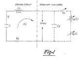
- This may be accomplished by using a very low inductance, low impedance, capacitive-discharge or driving circuit represented by the simplified equivalent model shown in FIGURE 1.
- driving circuit refers to all of the high voltage discharge circuit components, connecting conductors, and structures other than the breakdown gap and gaseous discharge path itself.
- Capacitor C represents the total effective discharge circuit capacitance
- inductor L o represents the total effective discharge circuit inductance
- resistance R o represents the total effective discharge circuit resistance.
- PPN pulse-forming-network
- L o includes the inductance of all connecting conductors and the inductance associated with the discrete or distributed capacitive unit and must generally be on the order of a few hundred nanohenries or less.
- R o includes the resistance of the circuit conductors as well as the effective resistive loss associated with dielectric losses in the capacitive element. In practice, R o should be no more than a few ohms, and preferably should be minimized to the sub-ohm level. In general, this approach toward ignition system operation contrasts with the prior art approach which lays heavy emphasis upon higher impedance, higher inductance, lower capacitance driving circuitry and considerably longer discharge duration at lower intensities.
- Cg is the capacitance of the gap prior to breakdown and is typically on the order of 10 picofarads (10pf).
- C g is important for storing the charge needed during the very early stages of the breakdown channel formation, but the magnitude of C g is small compared to C and can be neglected once the early breakdown channel has been established.
- Closing of switch S b represents the onset of the breakdown event in which an ionized current flow path is formed between the spark gap electrodes.
- maximum performance is obtained using voltages from 20 kV to 40 kV, and a discharge circuit capacitance of 100 picofarads to several nanofarads, values of L/l g on the order of a few hundred nanohenries of discharge circuit inductance (L) per centimeter of discharge gap length (l g ), or less, preferably equal to or less than 80 nanohenries per centimeter, depending on the value of capacitance C and the effective working gap breakdown electric field E o .
- FIGURE 2 wherein a discrete capacitance PFN is disclosed.
- the PFN generally indicated at 122 is formed in a coaxial cable 123 which connects a power supply (not shown) with a connector (not shown) which is adapted to connect the cable 123 with an ignitor.
- the PFN 122 comprises an inner conductor 130 surrounded by a sleeve 136 of high dielectric material, such as ceramic.
- a layer 134 of metalization on the outer surface of the dielectric sleeve 136 is connected with the outer conductor 127 and thus forms a continuous path for the flow of current through the cable 123.
- the inner conductor 130 is of substantially larger diameter than the central conductor 128 of the cable 123 and is connected at its ends to the central conductor 128 as by welding or the like.
- a layer of dielectric potting compound 132 surrounds the connection between the central conductor 128 and inner conductor 130.
- Inner connector 130 in combination with the dielectric sleeve 136 and metalization 134 forms a capacitor which is in close proximity to the ignitor 52.
- the PFN 122 provides a discharge circuit of high impedance and inductance, it possesses the advantage of providing an ignitor which is relatively small and eliminates the problem of deliterious effects on the capacitor by additional heat to which it is subjected if positioned contiguous to the combustion chamber.
- the PFN 144 is connected in series with the coaxial power supply cable 146 which connects the power supply (not shown) with a coaxial ignitor 52.
- the PFN 144 comprises first and second sets of flat plate capacitors 152, 154 which are interleafed and spaced apart using a dielectric material 156 to form a series of capacitor plates. Plates 12 are connected with the outer conductor of cable 146 while capacitor plates 154 are connected with its central conductor 148.
- a distributed capacitance PFN 158 is depicted in FIGURE 4A, which is formed integral with the distribution cable connecting the ignitor with the high vdltage power supply.
- the cable including the PFN 158 is substantially flexible but yet does not possess a diameter too large to be used in existing automobile engines.
- the PFN 158 comprises a stripline geometry in which a plurality of flexible, outer foil conductors 160 are interleafed with a plurality of inner foil conductors 164 and are separated therefrom by a plurality of layers 162 of dielectric material such as a polyamide film.
- the foil conductors 160, 164 may extend a substantial portion of the length of the entire cable and the sandwiched construction is enclosed by an outer rubber or plastic jacket 166.
- the stripline configuration may be terminated in a connector 168 which is adapted to. releasably connect the cable with an ignitor.
- the inner foil conductors 164 are terminated in a single connection which is secured to a center conductor 172 which in turn is connected with a metal contact 174 disposed within a cap 176 which fits over the terminal end of the ignitor.
- the foil conductors 160 are terminated in a connection with lead lines 170 within the cap 176. Contacts 174 and lead lines 170 respectively interconnect with the electrodes of the ignitor.
- FIGURE 4B Another form of distributed capacitance PFN is depicted in FIGURE 4B.
- the PFN comprises a coaxial cable 123 which is connected to an ignitor (not shown) by a connector 138.
- the connector 138 includes an outer threaded coupling 142 which is threadably received by a portion of the ignitor, and an inner electrical connecting portion 140 which electrically connects the electrodes of the ignitor with the central conductor 128 and outer conductor 127 of the cable 123.
- the inner and outer conductors 127 and 128 form the distributed capacitance.
Landscapes
- Engineering & Computer Science (AREA)
- Chemical & Material Sciences (AREA)
- Combustion & Propulsion (AREA)
- Mechanical Engineering (AREA)
- General Engineering & Computer Science (AREA)
- Plasma & Fusion (AREA)
- Physics & Mathematics (AREA)
- Ignition Installations For Internal Combustion Engines (AREA)
- Combustion Methods Of Internal-Combustion Engines (AREA)
- Spray-Type Burners (AREA)
- Cylinder Crankcases Of Internal Combustion Engines (AREA)
- Spark Plugs (AREA)
- Valve Device For Special Equipments (AREA)
- Electrical Discharge Machining, Electrochemical Machining, And Combined Machining (AREA)
Abstract
Description
- This invention relates to an apparatus for initiating combustion of fuel-air mixtures in an internal combustion engine, as defined in the preamble of
claim 1. - An apparatus of this kind is known from US-A-4,333,125. Furthermore, it is referred to Combustion and Flame 27, published 1976, R. Knystautas and J.H. Lee, on the Effective Energy for Direct Initiation of Gaseous Detonations, pages 221-228. The known apparatus includes a capacitive portion for storing a large quantity of electrical energy therein derived from a power supply, and an electrode portion integral with the capacitive portion which comprises a pair of concentric, rod shaped electrodes for producing a high energy, umbrella shaped plasma discharge, using the inverse pinch technique. Due to the close proximity between the capacitive and electrode portions of the initiating device, rapid energy transfer from the former to the latter creates high magnetic pressures which transform the discharge into a high energy plasma jet which is delivered well into the combustion area.
- According to this principle, despite the fact that the ignition can be enhanced, the power coupling efficiency from a relatively high impedance ignition source circuit to the very low impedance of an established discharge channel is quite low, resulting in a greater fraction of the available energy being lost through power dissipation in circuit resistance other than the discharge channel itself. Somewhat greater power dissipation in the discharge channel can be achieved by increasing the magnitude of current flow. However, for a given discharge duration, this may be accomplished only at the expense of greater energy input requirements and severe electrode wear.
- Accordingly, it is the problem to be solved by this invention to create an apparatus for igniting combustion of fuel-air mixtures, which generates a very rapid intense high power electric breakdown.
- The invention solves this problem by an aparatus having the features of
claim 1. Further developments of this apparatus are described in the subclaims. - The ignition apparatus of the present invention employs a hard-discharge-ignition (HDI) process which is generated by a very rapid, intense, high-power electrical breakdown which we shall refer to as a "hard" spark discharge. HDI initiation of combustion employs highly effective energy coupling mechanisms which reach high levels of intensity. The term "hard-discharge" as used herein refers to the regime of operation in which the discharge circuit inductance and resistance are sufficiently low that the rate of current flow and rate of energy deposition in the discharge channel during the breakdown phase are largely governed by the resistance of the spark channel itself.
- This extreme regime of operation is characterized by highly efficient coupling (80-95%) of the initially stored electrical circuit energy, during approximately the first half-period of the discharge current cycle, into the various transient processes associated with gaseous discharge formation and expansion. As a result, hard-discharge operation delivers most of the available pulse energy within the breakdown phase of the discharge (usually within the first few tens of nanoseconds of the discharge), thereby achieving maximum power-coupling from the driving circuit to the rapidly dropping effective load impedance of the discharge channel. Using typical discharge circuit energy levels of between 0.05 to 2 joules, and with rates of rise of breakdown current flow on the order of 1010 to 1012 amperes per second, the resulting power deposition can approach an order of 10's of megawatts within the time span of a few 10's of nanoseconds.
- Additionally, the greatly enhanced speed of the overall combustion event significantly reduces the amount of ignition timing advance necessary for MBT (maximum brake torque) operation with a given fuel-air mixture. Depending upon the mixture ratio, engine conditions, and HDI energy and power level, the need for timing advance may be entirely eliminated. Consequently, highly efficient engine operation is provided with significantly reduced ignition timing advance.
- In the drawings, which form an integral part of the specification and are to be read in conjunction therewith, and in which like reference numerals are employed to designate identical components in the various views:
- FIGURE 1 is a schematic diagram of an equivalent electrical circuit for generating a hard discharge ignition in accordance with the present invention;
- FIGURE 2 is a longitudinal sectional view of a distribution cable employing a pulse forming network (PFN) having lumped capacitance;
- FIGURE 3 is a perspective view, parts being broken away in section, of another distribution cable having a pulse forming network employing lumped capacitance;
- FIGURES 4A and 4B are longitudinal, sectional views of portions of distribution cables employing a pulse forming network having distributed capacitance;
- FIGURE 5 is a cross-sectional view of a termination connector for use with the distribution cable shown in FIGURE 4A;
- The rate of admission of energy into the breakdown channel in a spark gap must be maximized in order to achieve high power coupling efficiency and to maximize the intensity of the energy transfer mechanisms which are important in accordance with the present invention for ignition applications. This may be accomplished by using a very low inductance, low impedance, capacitive-discharge or driving circuit represented by the simplified equivalent model shown in FIGURE 1. As used in this description, the term "driving circuit" refers to all of the high voltage discharge circuit components, connecting conductors, and structures other than
the breakdown gap and gaseous discharge path itself. Capacitor C represents the total effective discharge circuit capacitance, inductor Lo represents the total effective discharge circuit inductance, and resistance Ro represents the total effective discharge circuit resistance. The reactive term component of the characteristic impedance of the discharge circuit is expressed as:
- The equivalent lumped circuit model components for the spark gap are indicated by dashed lines in FIGURE 1. Cg is the capacitance of the gap prior to breakdown and is typically on the order of 10 picofarads (10pf). Cg is important for storing the charge needed during the very early stages of the breakdown channel formation, but the magnitude of Cg is small compared to C and can be neglected once the early breakdown channel has been established. Closing of switch Sb represents the onset of the breakdown event in which an ionized current flow path is formed between the spark gap electrodes.
- The detailed mechanisms involved in this process depend upon the conditions of the gas in the gap and the manner in which the voltage is applied. For purposes of this disclosure, it may be assumed that the establishment of current flow across the gap may be represented by the closing of the switch Sb. Cg is then effectively shunted by the time-varying channel inductance Lg (t) and resistance Rg (t). The circuit operation begins after capacitor C is charged to an initial voltage Vo.
- For ignition applications of HDI, maximum performance is obtained using voltages from 20 kV to 40 kV, and a discharge circuit capacitance of 100 picofarads to several nanofarads, values of L/lg on the order of a few hundred nanohenries of discharge circuit inductance (L) per centimeter of discharge gap length (lg), or less, preferably equal to or less than 80 nanohenries per centimeter, depending on the value of capacitance C and the effective working gap breakdown electric field Eo.
- As a practical matter, reducing the overall circuit inductance to values of L/lg below approximately 10 nH/cm is quite difficult in high voltage discharge circuits where certain minimum physical spacing is required for electrical insulation. In fact, the breakdown channel itself typically has self-inductance on the order of 10nH/cm. In cases where insufficient hardness has been achieved despite the minimization of L/lg to practical limits, the major alternative for increasing hardness are to decrease the capacitance C and/or to effectively increase Eo by overvolting the discharge gap. Investigations with hard open air discharges have shown that for values of C less than or approximately equal to 3 nanofarads, an increase in energy caused by increasing the working voltage Vo and gap length lg yields a shorter discharge current duration and a longer duration of light output with light output in very hard discharges continuing well beyond the cessation of current flow (afterglow).
- Reference is now made to FIGURE 2 wherein a discrete capacitance PFN is disclosed. The PFN, generally indicated at 122 is formed in a
coaxial cable 123 which connects a power supply (not shown) with a connector (not shown) which is adapted to connect thecable 123 with an ignitor. - The PFN 122 comprises an inner conductor 130 surrounded by a sleeve 136 of high dielectric material, such as ceramic. A layer 134 of metalization on the outer surface of the dielectric sleeve 136 is connected with the
outer conductor 127 and thus forms a continuous path for the flow of current through thecable 123. The inner conductor 130 is of substantially larger diameter than thecentral conductor 128 of thecable 123 and is connected at its ends to thecentral conductor 128 as by welding or the like. A layer ofdielectric potting compound 132 surrounds the connection between thecentral conductor 128 and inner conductor 130. Inner connector 130 in combination with the dielectric sleeve 136 and metalization 134 forms a capacitor which is in close proximity to the ignitor 52. - Although the PFN 122 provides a discharge circuit of high impedance and inductance, it possesses the advantage of providing an ignitor which is relatively small and eliminates the problem of deliterious effects on the capacitor by additional heat to which it is subjected if positioned contiguous to the combustion chamber.
- Another form of discrete capacitance PFN is depicted in Figure 3. The PFN 144 is connected in series with the coaxial power supply cable 146 which connects the power supply (not shown) with a coaxial ignitor 52. The PFN 144 comprises first and second sets of
flat plate capacitors dielectric material 156 to form a series of capacitor plates. Plates 12 are connected with the outer conductor of cable 146 whilecapacitor plates 154 are connected with itscentral conductor 148. - A distributed capacitance PFN 158 is depicted in FIGURE 4A, which is formed integral with the distribution cable connecting the ignitor with the high vdltage power supply. The cable including the PFN 158 is substantially flexible but yet does not possess a diameter too large to be used in existing automobile engines. The PFN 158 comprises a stripline geometry in which a plurality of flexible, outer foil conductors 160 are interleafed with a plurality of
inner foil conductors 164 and are separated therefrom by a plurality oflayers 162 of dielectric material such as a polyamide film. Thefoil conductors 160, 164 may extend a substantial portion of the length of the entire cable and the sandwiched construction is enclosed by an outer rubber orplastic jacket 166. - As shown in FIGURE 5, the stripline configuration may be terminated in a connector 168 which is adapted to. releasably connect the cable with an ignitor. The
inner foil conductors 164 are terminated in a single connection which is secured to acenter conductor 172 which in turn is connected with ametal contact 174 disposed within acap 176 which fits over the terminal end of the ignitor. The foil conductors 160 are terminated in a connection withlead lines 170 within thecap 176.Contacts 174 andlead lines 170 respectively interconnect with the electrodes of the ignitor. - Another form of distributed capacitance PFN is depicted in FIGURE 4B. The PFN comprises a
coaxial cable 123 which is connected to an ignitor (not shown) by aconnector 138. Theconnector 138 includes an outer threadedcoupling 142 which is threadably received by a portion of the ignitor, and an inner electrical connectingportion 140 which electrically connects the electrodes of the ignitor with thecentral conductor 128 andouter conductor 127 of thecable 123. The inner andouter conductors
Claims (6)
- Apparatus for igniting the combustion of a fuel-air mixture in a spark gap of an ignitor in an internal combustion engine, comprising an electrical discharge circuit including a capacitor (122,144,158) for storing a quantity of electrical energy, and a pair of electrical conductors for electrically connecting said capacitor (122,144,158) with said ignitor (52), said capacitor (122, 158, 144) being inserted and/or distributed along at least a portion of an electrical distribution cable (123, 146, 180) for connecting said capacitor (122,144,158) with a high voltage source, characterized in that the capacitor has a capacitance of 100 to 5000 pi-cofarad, whereas the ratio of the inductance of said discharge circuit including the capacitor (122,144,158) to the length of said spark gap is less than approximately 80 nanohenries per centimeter.
- The apparatus of claim 1, characterized in that said distribution cable is a coaxial cable (123) the inner conductor (130) of which has an increased diameter on a certain length and is surrounded by a sleeve (136) of high dielectric material having an outer metallization layer (134) which is connected with the outer conductor (127) of said coaxial cable (123), the portion of increased diameter being connected at its ends with the inner conductor (128) of small diameter, the connection being surrounded by a layer (132) of dielectric potting compound.
- The apparatus of claim 1, characterized in that said distribution cable is a coaxial cable (146, 180) whose outer and inner conductor (148) is connected in series with first and second sets of flat interleafed and spaced apart capacitor plates (152, 154), respectively.
- The apparatus of claim 3, characterized by a stripline capacitor (158) formed integral with said coaxial distribution cable (180) in which a plurality of outer foil conductors (160) forming said first capacitor plates are interleafed with a plurality of inner foil conductors (164) forming said second capacitor plates and are separated therefrom by a plurality of layers (162) of dielectric material.
- The apparatus of claim 4, characterized in that the stripline capacitor (158) terminates in a connector (168) for the connection with an ignitor, said inner foil conductors (164) terminating in a single connection with a center conductor (172) within a cap (176) of said connector (168), and said outer conductors (160) terminating in a connection with lead lines (170) within said cap (176), said center conductor (172) and said lead lines (170) being connectable with the electrodes of said ignitor.
- The apparatus of claim 1, characterized in that said capacitor is formed by an inner and an outer conductor (127, 128) of a coaxial distribution cable (123) which terminates in a connector (138) having an electrical connecting portion (140) for connecting the electrodes of the ignitor with the conductors (127, 128) of said coaxial distribution cable (123).
Applications Claiming Priority (5)
| Application Number | Priority Date | Filing Date | Title |
|---|---|---|---|
| US583694 | 1984-02-27 | ||
| US06/583,694 US4589398A (en) | 1984-02-27 | 1984-02-27 | Combustion initiation system employing hard discharge ignition |
| US70148285A | 1985-02-14 | 1985-02-14 | |
| US701482 | 1985-02-14 | ||
| EP85901280A EP0174346B1 (en) | 1984-02-27 | 1985-02-26 | Combustion initiation system employing hard discharge ignition |
Related Parent Applications (2)
| Application Number | Title | Priority Date | Filing Date |
|---|---|---|---|
| EP85901280A Division EP0174346B1 (en) | 1984-02-27 | 1985-02-26 | Combustion initiation system employing hard discharge ignition |
| EP85901280.9 Division | 1985-02-26 |
Publications (3)
| Publication Number | Publication Date |
|---|---|
| EP0412576A2 EP0412576A2 (en) | 1991-02-13 |
| EP0412576A3 EP0412576A3 (en) | 1991-03-20 |
| EP0412576B1 true EP0412576B1 (en) | 1996-08-28 |
Family
ID=27078878
Family Applications (3)
| Application Number | Title | Priority Date | Filing Date |
|---|---|---|---|
| EP90117485A Expired - Lifetime EP0412576B1 (en) | 1984-02-27 | 1985-02-26 | Apparatus for igniting the combustion of a fuel-air mixture |
| EP85901280A Expired EP0174346B1 (en) | 1984-02-27 | 1985-02-26 | Combustion initiation system employing hard discharge ignition |
| EP90117487A Expired - Lifetime EP0408089B1 (en) | 1984-02-27 | 1985-02-26 | Apparatus for initiating combustion of fuel-air mixtures in an internal combustion engine |
Family Applications After (2)
| Application Number | Title | Priority Date | Filing Date |
|---|---|---|---|
| EP85901280A Expired EP0174346B1 (en) | 1984-02-27 | 1985-02-26 | Combustion initiation system employing hard discharge ignition |
| EP90117487A Expired - Lifetime EP0408089B1 (en) | 1984-02-27 | 1985-02-26 | Apparatus for initiating combustion of fuel-air mixtures in an internal combustion engine |
Country Status (9)
| Country | Link |
|---|---|
| EP (3) | EP0412576B1 (en) |
| AT (3) | ATE141999T1 (en) |
| AU (1) | AU3907885A (en) |
| CA (1) | CA1267930A (en) |
| DE (3) | DE3588073T2 (en) |
| GB (1) | GB2182718B (en) |
| IT (1) | IT1214652B (en) |
| SE (1) | SE453852B (en) |
| WO (1) | WO1985003980A1 (en) |
Families Citing this family (4)
| Publication number | Priority date | Publication date | Assignee | Title |
|---|---|---|---|---|
| DE3513422C2 (en) * | 1985-04-15 | 1993-10-28 | Beru Werk Ruprecht Gmbh Co A | Ignition system for internal combustion engines |
| FR2858024B1 (en) * | 2003-07-25 | 2007-11-16 | Peugeot Citroen Automobiles Sa | DEVICE FOR IGNITING AN AIR / FUEL MIXTURE |
| US9246698B2 (en) * | 2004-05-07 | 2016-01-26 | Nokia Technologies Oy | Apparatus, and associated method, for facilitating a radio resource measurement in a radio communication system |
| GB2584731B (en) | 2019-06-13 | 2024-01-31 | Bae Systems Plc | Pulse charging of a capacitor |
Family Cites Families (14)
| Publication number | Priority date | Publication date | Assignee | Title |
|---|---|---|---|---|
| BE573091A (en) * | ||||
| US2820087A (en) * | 1953-06-22 | 1958-01-14 | Globe Union Inc | Seals between metal conductors and ceramic insulators |
| FR1307681A (en) * | 1961-12-07 | 1962-10-26 | Lodge Plugs Ltd | Improvements to electric ignition systems |
| GB994525A (en) * | 1962-12-06 | 1965-06-10 | Gen Motors Ltd | Spark plugs |
| DE2363804A1 (en) * | 1973-12-21 | 1975-06-26 | Uwe Holtin | Sparking plug with integrated capacitor - has dielectric material and electrode elements arranged to form parallel capacitors |
| DE2400623A1 (en) * | 1974-01-08 | 1975-07-10 | Uwe C Seefluth | IC engine spark plug - has inner conductor to centre electrode, insulator and earthed casing with outer electrode |
| DE2628209A1 (en) * | 1975-06-24 | 1977-01-20 | Smiths Industries Ltd | IGNITION SYSTEM |
| GB1521313A (en) * | 1975-09-09 | 1978-08-16 | Lindsay M | Hybrid gap spark plug |
| GB2032516A (en) * | 1978-10-25 | 1980-05-08 | Huang Yu Fei | Sparking plug |
| US4324219A (en) * | 1979-02-16 | 1982-04-13 | Hayashi Seiko Kabushiki Kaisha | Spark intensifier in gasoline engine |
| US4333125A (en) * | 1980-02-08 | 1982-06-01 | Hensley George H | Combustion initiation system |
| US4402036A (en) * | 1980-02-08 | 1983-08-30 | Hensley George H | Method of producing a high energy plasma for igniting fuel |
| US4333126A (en) * | 1980-05-30 | 1982-06-01 | Hensley George H | Combustion initiation device |
| DE3308522A1 (en) * | 1983-03-10 | 1984-09-13 | Robert Bosch Gmbh, 7000 Stuttgart | SPARK PLUG FOR INTERNAL COMBUSTION ENGINES |
-
1985
- 1985-02-21 CA CA000474788A patent/CA1267930A/en not_active Expired - Fee Related
- 1985-02-22 IT IT8547719A patent/IT1214652B/en active
- 1985-02-22 AU AU39078/85A patent/AU3907885A/en not_active Abandoned
- 1985-02-26 WO PCT/US1985/000319 patent/WO1985003980A1/en not_active Ceased
- 1985-02-26 AT AT90117485T patent/ATE141999T1/en not_active IP Right Cessation
- 1985-02-26 EP EP90117485A patent/EP0412576B1/en not_active Expired - Lifetime
- 1985-02-26 AT AT90117487T patent/ATE131905T1/en not_active IP Right Cessation
- 1985-02-26 DE DE3588073T patent/DE3588073T2/en not_active Expired - Fee Related
- 1985-02-26 DE DE3588119T patent/DE3588119T2/en not_active Expired - Fee Related
- 1985-02-26 GB GB08525712A patent/GB2182718B/en not_active Expired
- 1985-02-26 DE DE8585901280T patent/DE3585113D1/en not_active Expired - Fee Related
- 1985-02-26 AT AT85901280T patent/ATE71432T1/en not_active IP Right Cessation
- 1985-02-26 EP EP85901280A patent/EP0174346B1/en not_active Expired
- 1985-02-26 EP EP90117487A patent/EP0408089B1/en not_active Expired - Lifetime
- 1985-10-25 SE SE8505033A patent/SE453852B/en not_active IP Right Cessation
Also Published As
| Publication number | Publication date |
|---|---|
| EP0412576A3 (en) | 1991-03-20 |
| WO1985003980A1 (en) | 1985-09-12 |
| DE3588119D1 (en) | 1996-10-02 |
| SE8505033D0 (en) | 1985-10-25 |
| EP0408089A3 (en) | 1991-03-20 |
| AU3907885A (en) | 1985-09-05 |
| GB2182718A (en) | 1987-05-20 |
| SE453852B (en) | 1988-03-07 |
| CA1267930A (en) | 1990-04-17 |
| DE3588073T2 (en) | 1996-05-30 |
| GB2182718B (en) | 1988-06-08 |
| ATE131905T1 (en) | 1996-01-15 |
| GB8525712D0 (en) | 1985-11-20 |
| ATE141999T1 (en) | 1996-09-15 |
| ATE71432T1 (en) | 1992-01-15 |
| EP0408089B1 (en) | 1995-12-20 |
| EP0174346A1 (en) | 1986-03-19 |
| EP0174346A4 (en) | 1986-07-30 |
| IT1214652B (en) | 1990-01-18 |
| DE3588073D1 (en) | 1996-02-01 |
| EP0412576A2 (en) | 1991-02-13 |
| EP0174346B1 (en) | 1992-01-08 |
| SE8505033L (en) | 1985-10-25 |
| DE3588119T2 (en) | 1997-02-27 |
| EP0408089A2 (en) | 1991-01-16 |
| DE3585113D1 (en) | 1992-02-20 |
| IT8547719A0 (en) | 1985-02-22 |
Similar Documents
| Publication | Publication Date | Title |
|---|---|---|
| US4774914A (en) | Electromagnetic ignition--an ignition system producing a large size and intense capacitive and inductive spark with an intense electromagnetic field feeding the spark | |
| US4402036A (en) | Method of producing a high energy plasma for igniting fuel | |
| US4589398A (en) | Combustion initiation system employing hard discharge ignition | |
| US10072629B2 (en) | Repetitive ignition system for enhanced combustion | |
| US6374816B1 (en) | Apparatus and method for combustion initiation | |
| GB1560812A (en) | Spark plug | |
| SU1074424A3 (en) | Arc-type ignition plug | |
| EP0044862B1 (en) | Ignition device for the combustion of fuel | |
| AU6780681A (en) | Combustion initiation system | |
| EP0174346B1 (en) | Combustion initiation system employing hard discharge ignition | |
| JPS63501520A (en) | Electromagnetic Ignition System - Large, strong, capacitive and inductive spark ignition system | |
| RU2010418C1 (en) | High-voltage pulse generator | |
| USRE32505E (en) | Combustion initiation system | |
| WO1981003525A1 (en) | Combustion initiation device | |
| SU877672A1 (en) | Controllable discharger | |
| CA1119907A (en) | Spark plug | |
| SU1345320A1 (en) | Pulse shaper | |
| SU813830A1 (en) | Device for power supply of pulse gas-discharge tubes | |
| SU1589344A1 (en) | Device for igniting fuel-air mixture | |
| RU1295978C (en) | Controlled discharger | |
| RU1424675C (en) | Controlled discharger | |
| Faidley et al. | The railplug: a new ignitor for internal combustion engines | |
| RU2213398C1 (en) | Three-electrode gas-discharge tube with circular electrodes | |
| WO2004100332A2 (en) | An auxiliary capacitive discharge ignition system configurable to provide additional energy at a spark gap and methods thereof | |
| MXPA98003091A (en) | Crown effect generator system for combusti engines |
Legal Events
| Date | Code | Title | Description |
|---|---|---|---|
| PUAI | Public reference made under article 153(3) epc to a published international application that has entered the european phase |
Free format text: ORIGINAL CODE: 0009012 |
|
| PUAL | Search report despatched |
Free format text: ORIGINAL CODE: 0009013 |
|
| AC | Divisional application: reference to earlier application |
Ref document number: 174346 Country of ref document: EP |
|
| AK | Designated contracting states |
Kind code of ref document: A2 Designated state(s): AT BE CH DE FR LI |
|
| AK | Designated contracting states |
Kind code of ref document: A3 Designated state(s): AT BE CH DE FR LI |
|
| 17P | Request for examination filed |
Effective date: 19910920 |
|
| RAP1 | Party data changed (applicant data changed or rights of an application transferred) |
Owner name: HENSLEY PLASMA PLUG PARTNERSHIP DBA HDI RESEARCH |
|
| 17Q | First examination report despatched |
Effective date: 19931029 |
|
| GRAA | (expected) grant |
Free format text: ORIGINAL CODE: 0009210 |
|
| AC | Divisional application: reference to earlier application |
Ref document number: 174346 Country of ref document: EP |
|
| AK | Designated contracting states |
Kind code of ref document: B1 Designated state(s): AT BE CH DE FR LI |
|
| PG25 | Lapsed in a contracting state [announced via postgrant information from national office to epo] |
Ref country code: LI Effective date: 19960828 Ref country code: CH Effective date: 19960828 |
|
| REF | Corresponds to: |
Ref document number: 141999 Country of ref document: AT Date of ref document: 19960915 Kind code of ref document: T |
|
| REF | Corresponds to: |
Ref document number: 3588119 Country of ref document: DE Date of ref document: 19961002 |
|
| ET | Fr: translation filed | ||
| PGFP | Annual fee paid to national office [announced via postgrant information from national office to epo] |
Ref country code: FR Payment date: 19970131 Year of fee payment: 13 Ref country code: BE Payment date: 19970131 Year of fee payment: 13 |
|
| PGFP | Annual fee paid to national office [announced via postgrant information from national office to epo] |
Ref country code: AT Payment date: 19970227 Year of fee payment: 13 |
|
| REG | Reference to a national code |
Ref country code: CH Ref legal event code: PL |
|
| PGFP | Annual fee paid to national office [announced via postgrant information from national office to epo] |
Ref country code: DE Payment date: 19970327 Year of fee payment: 13 |
|
| PLBE | No opposition filed within time limit |
Free format text: ORIGINAL CODE: 0009261 |
|
| STAA | Information on the status of an ep patent application or granted ep patent |
Free format text: STATUS: NO OPPOSITION FILED WITHIN TIME LIMIT |
|
| 26N | No opposition filed | ||
| PG25 | Lapsed in a contracting state [announced via postgrant information from national office to epo] |
Ref country code: AT Free format text: LAPSE BECAUSE OF NON-PAYMENT OF DUE FEES Effective date: 19980226 |
|
| PG25 | Lapsed in a contracting state [announced via postgrant information from national office to epo] |
Ref country code: FR Free format text: THE PATENT HAS BEEN ANNULLED BY A DECISION OF A NATIONAL AUTHORITY Effective date: 19980228 Ref country code: BE Free format text: LAPSE BECAUSE OF NON-PAYMENT OF DUE FEES Effective date: 19980228 |
|
| BERE | Be: lapsed |
Owner name: HENSLEY PLASMA PLUG PARTNERSHIP DBA HDI RESEARCH Effective date: 19980228 |
|
| PG25 | Lapsed in a contracting state [announced via postgrant information from national office to epo] |
Ref country code: DE Free format text: LAPSE BECAUSE OF NON-PAYMENT OF DUE FEES Effective date: 19981103 |
|
| REG | Reference to a national code |
Ref country code: FR Ref legal event code: ST |