EP0412441A2 - Multifunctional radar - Google Patents
Multifunctional radar Download PDFInfo
- Publication number
- EP0412441A2 EP0412441A2 EP90114878A EP90114878A EP0412441A2 EP 0412441 A2 EP0412441 A2 EP 0412441A2 EP 90114878 A EP90114878 A EP 90114878A EP 90114878 A EP90114878 A EP 90114878A EP 0412441 A2 EP0412441 A2 EP 0412441A2
- Authority
- EP
- European Patent Office
- Prior art keywords
- radar
- power
- function
- optimal
- lobe
- Prior art date
- Legal status (The legal status is an assumption and is not a legal conclusion. Google has not performed a legal analysis and makes no representation as to the accuracy of the status listed.)
- Granted
Links
Images


Classifications
-
- G—PHYSICS
- G01—MEASURING; TESTING
- G01S—RADIO DIRECTION-FINDING; RADIO NAVIGATION; DETERMINING DISTANCE OR VELOCITY BY USE OF RADIO WAVES; LOCATING OR PRESENCE-DETECTING BY USE OF THE REFLECTION OR RERADIATION OF RADIO WAVES; ANALOGOUS ARRANGEMENTS USING OTHER WAVES
- G01S13/00—Systems using the reflection or reradiation of radio waves, e.g. radar systems; Analogous systems using reflection or reradiation of waves whose nature or wavelength is irrelevant or unspecified
- G01S13/66—Radar-tracking systems; Analogous systems
- G01S13/72—Radar-tracking systems; Analogous systems for two-dimensional tracking, e.g. combination of angle and range tracking, track-while-scan radar
- G01S13/723—Radar-tracking systems; Analogous systems for two-dimensional tracking, e.g. combination of angle and range tracking, track-while-scan radar by using numerical data
-
- G—PHYSICS
- G01—MEASURING; TESTING
- G01S—RADIO DIRECTION-FINDING; RADIO NAVIGATION; DETERMINING DISTANCE OR VELOCITY BY USE OF RADIO WAVES; LOCATING OR PRESENCE-DETECTING BY USE OF THE REFLECTION OR RERADIATION OF RADIO WAVES; ANALOGOUS ARRANGEMENTS USING OTHER WAVES
- G01S7/00—Details of systems according to groups G01S13/00, G01S15/00, G01S17/00
- G01S7/02—Details of systems according to groups G01S13/00, G01S15/00, G01S17/00 of systems according to group G01S13/00
- G01S7/28—Details of pulse systems
-
- G—PHYSICS
- G01—MEASURING; TESTING
- G01S—RADIO DIRECTION-FINDING; RADIO NAVIGATION; DETERMINING DISTANCE OR VELOCITY BY USE OF RADIO WAVES; LOCATING OR PRESENCE-DETECTING BY USE OF THE REFLECTION OR RERADIATION OF RADIO WAVES; ANALOGOUS ARRANGEMENTS USING OTHER WAVES
- G01S13/00—Systems using the reflection or reradiation of radio waves, e.g. radar systems; Analogous systems using reflection or reradiation of waves whose nature or wavelength is irrelevant or unspecified
- G01S13/02—Systems using reflection of radio waves, e.g. primary radar systems; Analogous systems
- G01S2013/0236—Special technical features
- G01S2013/0245—Radar with phased array antenna
- G01S2013/0254—Active array antenna
-
- G—PHYSICS
- G01—MEASURING; TESTING
- G01S—RADIO DIRECTION-FINDING; RADIO NAVIGATION; DETERMINING DISTANCE OR VELOCITY BY USE OF RADIO WAVES; LOCATING OR PRESENCE-DETECTING BY USE OF THE REFLECTION OR RERADIATION OF RADIO WAVES; ANALOGOUS ARRANGEMENTS USING OTHER WAVES
- G01S13/00—Systems using the reflection or reradiation of radio waves, e.g. radar systems; Analogous systems using reflection or reradiation of waves whose nature or wavelength is irrelevant or unspecified
- G01S13/02—Systems using reflection of radio waves, e.g. primary radar systems; Analogous systems
- G01S2013/0236—Special technical features
- G01S2013/0272—Multifunction radar
Definitions
- the invention relates to a multifunction radar according to the preamble of patent claim 1.
- a multifunction radar with an electronically phased antenna has a number of tasks to perform.
- the following can be important: the search in different areas, the finding of objects for which there is pre-instruction, the clarification of possible false alarms and, if necessary, the quick initiation of target tracking, the tracking of targets of different categories, passive location (e.g. triangulation and trilateration) and that Detect clutter and shadowing.
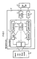
- the multifunction radar fulfills these tasks by the appropriate interaction of its assemblies shown in the figure.
- assemblies that take care of the physical generation of the transmission signals, as well as reception and signal processing, right up to plot formation.
- these are a signal generator 1, a transmitter 2, an electronically phase-controlled antenna 3, a receiver 4 and a received signal processing device 5.
- these modules which e.g. ensures that the phase shifters of the antenna 3 are set correctly, that the transmission and reception frequencies match and that the signal processing is carried out in such a way that it matches the signal being emitted.
- radar control device 6 The assembly that performs this coordination is referred to as radar control device 6. All previously mentioned assemblies are to be summarized under the term radar measuring device 7.
- the radar measuring device 7 defined in this way is capable of executing instructions in which it is determined where (lobe position), how long (illumination duration) and how (signal shape and signal processing form) the multifunction radar should "look". The duration of the lighting is determined by the signal shape.
- Such an instruction which consists of the lobe position, signal form and signal processing form, should be referred to as an elementary radar task.
- the radar measuring device must therefore receive elementary radar orders. It then generates depending on the state of the outside world, i.e. the scenario 8, plots or strobes and delivers them to a multifunction radar target tracking device (tracker) 9, which processes this information.
- the processed information is delivered to a fire control station 10.
- the effort in the construction of the radar measuring device 7 is reflected in the number of executable elementary radar orders.
- a lobe position can be freely selected within a solid angle range.
- the dwell time in this lobe position, the signal form and the signal processing form can also be selected from a wide variety of possibilities. If one also takes into account the fact that in general several hundred such elementary radar orders are to be generated per second, one obtains an idea of the abundance of technical possibilities which the radar measuring device makes available.
- a radar management module 11 should now be understood to mean that module of a multifunction radar which, by skillful use of the radar measuring device 7, ensures that the multifunction radar optimally fulfills all of its tasks indicated above, and that any conflicts of interest that arise are properly resolved.
- the task of the radar management assembly 11 is to at any time cheapest elementary radar order.
- the complexity of radar management results from the vast number of possible combinations of elementary radar orders.
- the best combination is to be selected for each time interval, so that the above-mentioned tasks of the multifunction radar, which is denoted by 12 in the figure, are optimally fulfilled.
- the object of the invention is to treat the generation of the most frequently occurring elementary radar orders as precisely as possible, so that there is a basic framework for radar management. Since the operation under ECM conditions is typical for the use of a multifunction radar, this leads to the special task of the best transmission power distribution in the room as a function of the interference power distribution during the search. The search places the most demands on the radar management, because the most degrees of freedom are available here.
- the quality of transmission power distributions which is dependent on the environment and location, can be described using a utility function. According to the invention, their dynamic optimization then leads to the best search performance distribution and further to the generation of the best elementary radar orders in the search.
- the radar manager In addition to the search, which in typical operation is likely to take up far more than half of the elementary radar orders, the radar manager must take into account all of the previously mentioned tasks of the multifunction radar and generate and plan corresponding elementary radar orders. The planning of the non-search orders is not dealt with here.
- the aim of the search activities of a radar is to detect objects that fly into the space to be monitored as early as possible. This is usually said as follows:
- the range should be as high as possible.
- range terms which must be clearly differentiated, especially if the sampling period is freely selectable. It points out their dependence on the generally unknown and very wide-ranging properties of the objects to be discovered.
- a range term, the monitoring range, which is suitable for the optimization of the radar management is selected.
- the invention also contains optimization information in the case of shadowing or clutter. Since the exact solution to this optimization task contains the optimal signal form selection in detail, no general solution can be given.
- the "clear range” says nothing about the probability of detection of concrete objects.
- the "cumulative detection range" is also unsuitable because it is difficult to handle analytically, but it also assumes that the sampling period is planned ahead over several samples. However, this requirement cannot be met in highly dynamic scenarios (including switching on / off interferers) if the radar should adapt to the situation as quickly as possible and consequently adapt its sampling period again and again.
- the monitoring range is used as the optimality criterion
- R ü R d - v R. T (1) proposed, where R d is the single detection range, v R the radial speed of the "object to be discovered” (towards the radar) and T the sampling period. That v R and R d depend on the behavior and the properties of the "object to be discovered” already shows that the procedure is "Bayesian". This means that the optimization is based on an a priori assumption about the environment that the radar is likely to encounter.
- R d depends on the environmental influences (ECM, clutter), on the fixed radar parameters, on the variable radar parameters (signal form) and the desired detection probability p D (eg 95%).
- ECM environmental influences
- p D variable radar parameters
- Monitoring range is that range R ü, can be guaranteed for the p at the assumed "to be detected objects", and the environmental conditions adopted with probability D, that a radially einfcedes with velocity v R object at a distance R ⁇ R e is detected.
- the invention shows how the optimization of the monitoring range in a lobe position provides the optimal values for monitoring range, signal shape and sampling period for this lobe position as a function of the available power component.
- Equation (6) provides the optimized monitoring range as a function of the power share; equation (5) indicates the associated optimal sampling period.
- T B is the only parameter in (2).
- a pulse would be optimal if you optimize the clear range as a secondary criterion.
- Equation (2) for the single detection range as a function of the signal shape is only approximately correct. If you want to take shading and clutter into account, you have to generalize this equation.
- the signal form is only received via the illumination time T B.
- the unique range is larger (but only slightly larger) than R o . This consideration applies to the case P> P o . Otherwise, the statements made in connection with the explanation of the basic case about the waveform selection remain valid.
- the monitoring range R u , the signal form and signal processing form and the sampling period are obtained as a function of the power component P of a lobe.
- search performance is first operationalized, namely by means of a utility function.
- This utility function is then optimized under the constraint of a limited amount of power available. This optimization takes place on the one hand if there is no clutter and no shading in all clubs involved, whereby borderline cases are also discussed which correspond to the requirement for a uniform monitoring range on the one hand and a fixed power distribution on the other hand. On the other hand, there is an optimization for the general case, i.e. also for cases with club positions in which clutter and shadowing are present. This leads to a method for generating search requests. This method optimizes a utility function defined below, but at the same time realizes a dynamic adaptation to changes in time and external influences.
- a phased array radar opens up the possibility of making the coverage area very flexible, whereby the question arises which of the realizable coverage areas is optimal.
- the answer to this question is one step closer if it is possible to decide whether each of the two coverage areas is "equally good” or which of the two coverage areas is “better”. Then you can define a utility function on the set of coverage areas, their optimization then leads to the "optimal" realizable coverage area.
- a coverage area A is "better" than a second B if the monitoring range in A is greater in every solid angle element than in B.
- the utility function must be a monotonically increasing function of the monitoring ranges in all lobe positions: u (R1, R2, ..., R n ) ⁇ u (R′1, R′2, ..., R ′ n ) (20) if R1 ⁇ R′1, R2 ⁇ R′2, ..., R n ⁇ R ′ n , where n is the number of lobe positions, and R i (or R ′ i ) is the monitoring range in the i-th lobe.
- the c i will normally not differ from lobe position to lobe position, but will have a uniform value in solid angle areas with a uniform threat situation.
- Equation (6) was derived for the monitoring range for the so-called basic case, which is not repeated here.
- the power component p i is proportional to the interference power N i . This means that because of (15) there is the same monitoring range in each club. It also follows that the sampling period is also uniform for all clubs.
- Equation (37) has exactly one solution for each ⁇ > ⁇ min .
- this procedure leads directly to a practicable procedure for parameters that change over time, i.e. it can be used for dynamic optimization.
- this method thus corrects both the power component of the affected club position and ⁇ in such a way that both (37) and (38) "approximately in the longer term" are fulfilled.
- the advantage of the iterative approach presented compared to trying to plan the p i exactly for a long time is the better ability to react to a changing environment.
- the search task can be solved through online planning.
- each lobe position can either not be illuminated at all or at any time. In this case, apart from initialization problems, which will be dealt with later, the time organization is very simple.
- the easiest way to do this is to provide an initialization set that e.g. ensures that the low elevations are scanned first, whereby all azimuth values are equal.
- the optimization of the waveform selection in clutter requires at least information about whether clutter is in the relevant lobe position or not.
- other parameters are required for better optimization, e.g. an assumption about the clutter type (volume or ground clutter), an estimate of the clutter density (in extreme cases as a function of the distance), an estimate of the distance range in which the clutter occurs, and an estimate of the (radial) speed of the clutter and its scatter Speed.
Abstract
Für eine Antennenkeulenposition wird für die Suchfunktion bei vorgegebenem Leistungsanteil eine Optimierung der Überwachungsreichweite erreicht, wodurch auch die günstigste Signalform, die günstigste Signalverarbeitungsform und die günstigste Abtastperiode geliefert werden. Im Grundfall, d.h. weder bei Vorliegen von Clutter noch von Abschattungen, zur Optimierung der Leistungsnutzung des für die Suche vorgegebenen Leistungsanteils P in einer Antennenkeule eine optimale Abtastperiode <IMAGE> und eine optimale Überwachungsreichweite <IMAGE> vorgesehen sind, wobei vR die Radialgeschwindigkeit eines zu entdeckenden, auf das Radar zufliegenden Objektes, c' eine vom zu entdeckenden Objekt und den festen Radarparametern abhängende Konstante, N die Rauschleistungsdichte, Rd = c'(TB/N)<1/4> die Einzelentdeckungsreichweite und TB die gesamte Dauer der Signalform ist. <IMAGE>For an antenna beam position, an optimization of the monitoring range is achieved for the search function with a predetermined power component, whereby the cheapest signal form, the cheapest signal processing form and the cheapest sampling period are also delivered. In the basic case, i.e. an optimal scanning period <IMAGE> and an optimal monitoring range <IMAGE> are not provided in an antenna lobe, neither in the presence of clutter nor shadowing, in order to optimize the power utilization of the power component P specified for the search, where vR is the radial speed of one to be detected on the radar flying object, c 'a constant depending on the object to be discovered and the fixed radar parameters, N the noise power density, Rd = c' (TB / N) <1/4> the individual detection range and TB the total duration of the signal form. <IMAGE>
Description
Die Erfindung bezieht sich auf ein Multifunktionsradar gemäß dem Oberbegriff des Patentanspruchs 1.The invention relates to a multifunction radar according to the preamble of patent claim 1.
Ein Multifunktionsradar mit einer elektronisch phasengesteuerten Antenne hat eine Reihe von Aufgaben zu erfüllen. Insbesondere können wichtig sein: die Suche in verschiedenen Bereichen, das Auffinden von Objekten, für die eine Voreinweisung vorliegt, die Klärung möglicher Fehlalarme und gegebenenfalls die schnelle Zielverfolgungsinitiierung, die Verfolgung von Zielen verschiedener Kategorien, die passive Ortung (z.B. Triangulation und Trilateration) und das Erkennen von Clutter und Abschattungen.A multifunction radar with an electronically phased antenna has a number of tasks to perform. In particular, the following can be important: the search in different areas, the finding of objects for which there is pre-instruction, the clarification of possible false alarms and, if necessary, the quick initiation of target tracking, the tracking of targets of different categories, passive location (e.g. triangulation and trilateration) and that Detect clutter and shadowing.
Das Multifunktionsradar erfüllt diese Aufgaben durch das geeignete Zusammenwirken seiner in der Figur dargestellten Baugruppen. Zunächst gibt es dabei Baugruppen, die für die physikalische Generierung der Sendesignale, sowie für den Empfang und die Signalverarbeitung bis zur Plotbildung sorgen. Im einzelnen sind dies ein Signalgenerator 1, ein Sender 2, eine elektronisch phasengesteuerte Antenne 3, ein Empfänger 4 und eine Empfangssignalverarbeitungseinrichtung 5. Dazu tritt die elementare Koordination dieser Baugruppen, die z.B. sicherstellt, daß die Phasenschieber der Antenne 3 korrekt eingestellt sind, daß die Sende- und Empfangsfrequenzen zusammenstimmen und daß die Signalverarbeitung so erfolgt, daß sie zum gerade ausgesandten Signal paßt.The multifunction radar fulfills these tasks by the appropriate interaction of its assemblies shown in the figure. First of all, there are assemblies that take care of the physical generation of the transmission signals, as well as reception and signal processing, right up to plot formation. Specifically, these are a signal generator 1, a transmitter 2, an electronically phase-controlled antenna 3, a receiver 4 and a received signal processing device 5. In addition, there is the elementary coordination of these modules, which e.g. ensures that the phase shifters of the antenna 3 are set correctly, that the transmission and reception frequencies match and that the signal processing is carried out in such a way that it matches the signal being emitted.
Die Baugruppe, die diese Koordination durchführt, wird als Radarsteuerungeseinrichtung 6 bezeichnet. Alle bisher erwähnten Baugruppen sollen unter dem Begriff Radarmeßgerät 7 zusammengefaßt werden.The assembly that performs this coordination is referred to as radar control device 6. All previously mentioned assemblies are to be summarized under the term radar measuring device 7.
Das so definierte Radarmeßgerät 7 ist in der Lage, Anweisungen auszuführen, in denen festgelegt ist, wohin (Keulenposition), wie lange (Beleuchtungsdauer) und wie (Signalform und Signalverarbeitungsform) das Multifunktionsradar "schauen" soll. Dabei ist die Beleuchtungsdauer durch die Signalform festgelegt. Eine solche Anweisung, die aus Keulenposition, Signalform und Signalverarbeitungsform besteht, soll als elementarer Radarauftrag bezeichnet werden. Das Radarmeßgerät muß also elementare Radaraufträge erhalten. Es generiert dann in Abhängigkeit vom Zustand der Außenwelt, d.h. dem Szenario 8, Plots bzw. Strobes und liefert diese an eine Multifunktionsradar- Zielverfolgungseinrichtung (Tracker) 9, die diese Informationen verarbeitet. Die verarbeitete Information wird an einen Feuerleitstand 10 geliefert.The radar measuring device 7 defined in this way is capable of executing instructions in which it is determined where (lobe position), how long (illumination duration) and how (signal shape and signal processing form) the multifunction radar should "look". The duration of the lighting is determined by the signal shape. Such an instruction, which consists of the lobe position, signal form and signal processing form, should be referred to as an elementary radar task. The radar measuring device must therefore receive elementary radar orders. It then generates depending on the state of the outside world, i.e. the scenario 8, plots or strobes and delivers them to a multifunction radar target tracking device (tracker) 9, which processes this information. The processed information is delivered to a fire control station 10.
Der Aufwand bei der Konstruktion des Radarmeßgeräts 7 schlägt sich nieder in der Menge ausführbarer elementarer Radaraufträge. Bei einem Phased-Array-Radar mit schmalem Radarstrahl ("Bleistiftkeule") kann innerhalb eines Raumwinkelbereichs eine Keulenposition frei ausgewählt werden. Die Verweildauer in dieser Keulenposition, die Signalform und die Signalverarbeitungsform können ebenfalls aus einer großen Vielfalt von Möglichkeiten ausgewählt werden. Berücksichtigt man darüber hinaus, daß im allgemeinen mehrere 100 solcher elementarer Radaraufträge pro Sekunde zu generieren sind, so erhält man eine Vorstellung von der Fülle technisch angelegter Möglichkeiten, die das Radarmeßgerät zur Verfügung stellt.The effort in the construction of the radar measuring device 7 is reflected in the number of executable elementary radar orders. With a phased array radar with a narrow radar beam ("pencil lobe"), a lobe position can be freely selected within a solid angle range. The dwell time in this lobe position, the signal form and the signal processing form can also be selected from a wide variety of possibilities. If one also takes into account the fact that in general several hundred such elementary radar orders are to be generated per second, one obtains an idea of the abundance of technical possibilities which the radar measuring device makes available.
Unter einer Radarmanagement-Baugruppe 11 soll nun diejenige Baugruppe eines Multifunktionsradars verstanden werden, die durch geschickte Nutzung des Radarmeßgerätes 7 dafür sorgt, daß das Multifunktionsradar alle seine oben angedeuteten Aufgaben optimal erfüllt, und daß dabei etwa auftretende Zielkonflikte sachgerecht gelöst werden.A radar management module 11 should now be understood to mean that module of a multifunction radar which, by skillful use of the radar measuring device 7, ensures that the multifunction radar optimally fulfills all of its tasks indicated above, and that any conflicts of interest that arise are properly resolved.
Vom Radarmeßgerät 7 aus gesehen besteht die Aufgabe der Radarmangement-Baugruppe 11 darin, zu jedem Zeitpunkt den günstigsten elementaren Radarauftrag zu erteilen. Die Komplexität des Radarmanagements resultiert dabei aus der unüberschaubar großen Anzahl der möglichen Kombinationen elementarer Radaraufträge.Seen from the radar measuring device 7, the task of the radar management assembly 11 is to at any time cheapest elementary radar order. The complexity of radar management results from the vast number of possible combinations of elementary radar orders.
Darunter ist in Abhängigkeit von den sich andauernd ändernden Umwelteinflüssen und der ebenfalls dynamischen taktischen Lage für jedes Zeitintervall die beste Kombination auszuwählen, damit die oben angedeuteten Aufgaben des Multifunktionsradars, das in der Figur mit 12 bezeichnet ist, optimal erfüllt werden.Depending on the constantly changing environmental influences and the likewise dynamic tactical position, the best combination is to be selected for each time interval, so that the above-mentioned tasks of the multifunction radar, which is denoted by 12 in the figure, are optimally fulfilled.
Bisher wurden Radarmanagement-Probleme bei Multifunktionsradaren mit phasengesteuerten Antennen mittels heuristischer Verfahren angegangen, die keine angebbaren Zielfunktionen optimieren, offline vorgeplante Betriebsmoden zur Lösung der Suchaufgabe benutzen und eine nur beschränkte und langsame Anpassung an die veränderliche Umwelt zulassen.So far, radar management problems with multifunction radars with phase-controlled antennas have been tackled using heuristic methods that do not optimize target functions that can be specified, use offline pre-planned operating modes to solve the search task and allow only limited and slow adaptation to the changing environment.
Im Aufsatz von B.H. Scheff, D.G. Hammel: "Real-Time Computer Control of Phased Array Radars" in "Supplement to IEEE Transactions on Aerospace and Electronic Systems" Vol. AES-3, No. 6, Nov. 1967, Seiten 198 bis 206 ist ein mit einer elektronisch phasengesteuerten Antenne ausgestattetes Multifunktionsradar beschrieben, das in Realzeit rechnergesteuert wird und dessen Betriebsablauffolgen durch ein Management-Programm ausgeführt werden.In the essay by B.H. Scheff, D.G. Hammel: "Real-Time Computer Control of Phased Array Radars" in "Supplement to IEEE Transactions on Aerospace and Electronic Systems" Vol. AES-3, No. 6, Nov. 1967, pages 198 to 206 describes a multifunction radar equipped with an electronically phase-controlled antenna, which is computer-controlled in real time and whose operational sequences are carried out by a management program.
Aufgabe der Erfindung ist es, die Erzeugung der am häufigsten auftretenden elementaren Radaraufträge möglichst exakt zu behandeln, damit ein Grundgerüst für das Radarmanagement da ist. Da für den Einsatz eines Multifunktionsradars der Betrieb unter ECM-Bedingungen typisch ist, führt dies zur besonderen Aufgabe der besten Sendeleistungsverteilung im Raum als Funktion der Störleistungsverteilung bei der Suche. Die Suche stellt an das Radarmanagement die meisten Anforderungen, weil hier die meisten Freiheitsgrade vorhanden sind.The object of the invention is to treat the generation of the most frequently occurring elementary radar orders as precisely as possible, so that there is a basic framework for radar management. Since the operation under ECM conditions is typical for the use of a multifunction radar, this leads to the special task of the best transmission power distribution in the room as a function of the interference power distribution during the search. The search places the most demands on the radar management, because the most degrees of freedom are available here.
Gemäß der Erfindung wird die gestellte Aufgabe durch die in den Patentansprüchen angegebenen Merkmale gelöst.According to the invention, the object is achieved by the features specified in the claims.
Die von Umwelt und Lage abhängige Güte von Sendeleistungsverteilungen läßt sich mittels einer Nutzenfunktion beschreiben. Deren dynamische Optimierung führt nach der Erfindung dann zur besten Suchleistungsverteilung und weiter zur Generierung der besten elementaren Radaraufträge bei der Suche.The quality of transmission power distributions, which is dependent on the environment and location, can be described using a utility function. According to the invention, their dynamic optimization then leads to the best search performance distribution and further to the generation of the best elementary radar orders in the search.
Neben der Suche, die im typischen Betrieb weit mehr als die Hälfte der elementaren Radaraufträge beanspruchen dürfte, muß der Radarmanager alle vorher genannten Aufgaben des Multifuntionsradars berücksichtigen und entsprechende elementare Radaraufträge generieren und einplanen. Die Planung der Nicht-Suchaufträge wird hier nicht behandelt.In addition to the search, which in typical operation is likely to take up far more than half of the elementary radar orders, the radar manager must take into account all of the previously mentioned tasks of the multifunction radar and generate and plan corresponding elementary radar orders. The planning of the non-search orders is not dealt with here.
Die Erfindung wird im folgenden im einzelnen beschrieben.The invention is described in detail below.
Die Zeichnungen zeigen in
- Fig. 1 das Blockschaltbild des bereits erläuterten Multifunktionsradars,
- Fig. 2 und 3 zwei unterschiedliche Bedeckungsdiagramme, und
- Fig. 4 den Verlauf einer den Forderungen entsprechenden Nutzenfunktion.
- Fig. 5, 6 und 7 drei Fälle zur Illustration der Reichweitenrücknahme bei Störung.
- 1 shows the block diagram of the multifunction radar already explained,
- 2 and 3 two different coverage diagrams, and
- Fig. 4 shows the course of a utility function corresponding to the requirements.
- 5, 6 and 7 three cases to illustrate the reduction in range in the event of a fault.
Ziel der Suchaktivitäten eines Radars ist es, Objekte, die in den zu überwachenden Raum einfliegen, möglichst frühzeitig zu entdecken. Üblicherweise formuliert man das so: Die Reichweite soll möglichst hoch sein. Allerdings gibt es verschiedene Reichweitenbegriffe, die insbesondere dann, wenn die Abtastperiode frei wählbar ist, sauber unterschieden werden müssen. Dabei wird auf ihre Abhängigkeit von den im allgemeinen unbekannten und sehr weit streuenden Eigenschaften der zu entdeckenden Objekte hingewiesen. Weiter wird ein für die Optimierung des Radarmanagements geeigneter Reichweitenbegriff, die Überwachungsreichweite, ausgewählt.The aim of the search activities of a radar is to detect objects that fly into the space to be monitored as early as possible. This is usually said as follows: The range should be as high as possible. However, there are different range terms, which must be clearly differentiated, especially if the sampling period is freely selectable. It points out their dependence on the generally unknown and very wide-ranging properties of the objects to be discovered. Furthermore, a range term, the monitoring range, which is suitable for the optimization of the radar management is selected.
Wie die Überwachungsreichweite im Grundfall, d.h. kein Clutter, keine Abschattungen, wohl aber Rauschstörer zugelassen, nach der Erfindung optimiert werden kann, wird gezeigt. Unter vertretbaren vereinfachenden Ausnahmen ist dies analytisch möglich. Es resultieren aus dieser Optimierung dreierlei Ergebnisse, nämlich die Überwachungsreichweite als Funktion des Leistungsanteils, die Signalform und Signalverarbeitungsform als Funktion des Leistungsanteils und die Abtastperiode als Funktion des Leistungsanteils.Like the monitoring range in the basic case, i.e. no clutter, no shadowing, but noise disturbers allowed, according to the invention can be optimized, is shown. With justifiable simplifying exceptions, this is possible analytically. This optimization results in three different results, namely the monitoring range as a function of the power component, the signal shape and signal processing form as a function of the power component and the sampling period as a function of the power component.
Die Erfindung enthält auch Optimierungsangaben im Fall von Abschattungen bzw. Clutter. Da die exakte Lösung dieser Optimierungsaufgabe die optimale Signalform-Auswahl im Detail beinhaltet, läßt sich keine allgemeine Lösung angeben.The invention also contains optimization information in the case of shadowing or clutter. Since the exact solution to this optimization task contains the optimal signal form selection in detail, no general solution can be given.
In der Radartechnik spielen verschiedene Reichweitenbegriffe eine Rolle. Hiervon sind allerdings die am meisten verbreiteten zur Problemlösung wenig geeignet: Die "eindeutige Reichweite" sagt nichts über die Entdeckungswahrscheinlichkeit konkreter Objekte aus. Die "Einzelentdeckungsreichweite" ist als Optimalitätskriterium nur geeignet, wenn die Abtastperiode (= Zeit zwischen zwei aufeinanderfolgenden Beleuchtungen derselben Keulenposition) a priori vorgegeben ist. Ohne diese Vorgabe würde die Optimierung zu unendlich langen Abtastperioden führen.Different range terms play a role in radar technology. Of these, however, the most widespread are unsuitable for problem solving: The "clear range" says nothing about the probability of detection of concrete objects. The "single detection range" is only suitable as an optimality criterion if the sampling period (= time between two successive illuminations of the same lobe position) is predetermined a priori. Without this specification, the optimization would lead to infinitely long sampling periods.
Auch die "kumulative Entdeckungsreichweite" ist wenig geeignet, da sie einmal analytisch schwer handhabbar ist, außerdem aber davon ausgeht, daß die Abtastperiode über mehrere Abtastungen hinweg vorausgeplant wird. Diese Voraussetzung ist aber in hochdynamischen Szenarien (u.a. mit Ein-/Ausschalten von Störern) nicht zu erfüllen, wenn sich das Radar schnellstmöglich an die Situation anpassen und folglich seine Abtastperiode immer wieder adaptieren soll.The "cumulative detection range" is also unsuitable because it is difficult to handle analytically, but it also assumes that the sampling period is planned ahead over several samples. However, this requirement cannot be met in highly dynamic scenarios (including switching on / off interferers) if the radar should adapt to the situation as quickly as possible and consequently adapt its sampling period again and again.
Bei der Erfindung wird als Optimalitätskriterium die Überwachungsreichweite
Rü = Rd - vR . T (1)
vorgeschlagen, wobei Rd die Einzelentdeckungsreichweite ist, vR die Radialgeschwindigkeit des "zu entdeckenden Objekts" (auf das Radar zu) und T die Abtastperiode. Daß vR und Rd vom Verhalten und von den Eigenschaften des "zu entdeckenden Objekts" abhängen, zeigt schon, daß die Vorgehensweise "Bayes'sch" ist. D.h. die Optimierung basiert auf einer a priori-Annahme über die Umwelt, die das Radar voraussichtlich antreffen wird.In the invention, the monitoring range is used as the optimality criterion
R ü = R d - v R. T (1)
proposed, where R d is the single detection range, v R the radial speed of the "object to be discovered" (towards the radar) and T the sampling period. That v R and R d depend on the behavior and the properties of the "object to be discovered" already shows that the procedure is "Bayesian". This means that the optimization is based on an a priori assumption about the environment that the radar is likely to encounter.
Rd hängt außer von den Eigenschaften des "zu entdeckenden Objekts" von den Umwelteinflüssen (ECM, Clutter), von den festen Radarparametern, von den variablen Radarparametern (Signalform) und der angestrebten Entdeckungswahrscheinlichkeit pD (z.B. 95 %) ab. Die Überwachungsreichweite läßt sich verbal so interpretieren:In addition to the properties of the "object to be discovered", R d depends on the environmental influences (ECM, clutter), on the fixed radar parameters, on the variable radar parameters (signal form) and the desired detection probability p D (eg 95%). The monitoring range can be interpreted verbally as follows:
Überwachungsreichweite ist diejenige Entfernung Rü, für die bei den angenommenen "zu entdeckenden Objekten" und den angenommenen Umweltbedingungen mit Wahrscheinlichkeit pD garantiert werden kann, daß ein radial mit Geschwindigkeit vR einfliegendes Objekt in einer Entfernung R ≧ Rü entdeckt wird.Monitoring range is that range R ü, can be guaranteed for the p at the assumed "to be detected objects", and the environmental conditions adopted with probability D, that a radially einfliegendes with velocity v R object at a distance R ≧ R e is detected.
Die im Zusammenhang mit der vorliegenden Erfindung gegebene Interpretation der Formel (1) strebt eine hohe sichere Entdeckungsentfernung (pD-Quantil) an. Letzteres führt bei gleicher Objektgeschwindigkeit zu wesentlich kürzeren Abtastperioden als die Optimierung einer mittleren Entdeckungsreichweite.The interpretation of formula (1) given in connection with the present invention strives for a high safe detection distance (p D quantile). The latter leads to much shorter sampling periods than the optimization of an average detection range at the same object speed.
Für die Überwachungsreichweite als Optimalitätskriterium spricht insbesondere das Prinzip der größtmöglichen Einfachheit. Sie ist die einfachste Reichweitendefinition, die eine sinnvolle Optimierung der Abtastperiode ermöglicht. Im gleich zu behandelnden "Grundfall" der Abhängigkeit Rd(T) ermöglicht sie sogar eine analytische Optimierung.The principle of the greatest possible simplicity speaks in favor of the monitoring range as an optimality criterion. It is the simplest range definition that enables a sensible optimization of the sampling period. In the "basic case" of the dependency R d (T) to be treated in the same way, it even enables analytical optimization.
Die Erfindung zeigt, wie die Optimierung der Überwachungsreichweite in einer Keulenposition die optimalen Werte für Überwachungsreichweite, Signalform und Abtastperiode für diese Keulenposition als Funktion des zur Verfügung stehenden Leistungsanteils liefert.The invention shows how the optimization of the monitoring range in a lobe position provides the optimal values for monitoring range, signal shape and sampling period for this lobe position as a function of the available power component.
Im folgenden soll die Optimierung der Überwachungsreichweite im Grundfall erläutert werden.The optimization of the monitoring range in the basic case will be explained below.
Bei einem Luftverteidigungsradar wird man den ECM-Fall als denjenigen Fall ansehen müssen, der die Auslegung bestimmen sollte. Hat man sonst günstige Verhältnisse (kein Clutter, keine Abschattungen), dann läßt sich die (Einzel-) Entdeckungsreichweite in erster Näherung durch folgende Version der Radargleichung ausdrücken:
Rd = c′ (TB / N)1/4 , (2)
wobei c′ eine Konstante ist, die vom "zu entdeckenden Objekt" und den festen Radarparametern abhängt. N ist die Rauschleistungsdichte. TB ist die gesamte Dauer der Signalform, wobei die Annahme zugrunde liegt, daß die Energie der Signalform proportional zu TB ist.With an air defense radar, the ECM case will have to be seen as the case that should determine the design. If you have otherwise favorable conditions (no clutter, no shadowing), then the (individual) detection range can be expressed in a first approximation by the following version of the radar equation:
R d = c ′ (T B / N) 1/4 , (2)
where c 'is a constant that depends on the "object to be discovered" and the fixed radar parameters. N is the noise power density. T B is the total duration of the waveform, based on the assumption that the energy of the waveform is proportional to T B.
Der Leistungsanteil, der für eine Keulenposition zur Verfügung steht, ist nun gegeben durch:
P = TB / T, (3)
da die mittlere Leistung konstant bleibt. Wird nun P als vorgegeben angesehen, so erhält man durch Einsetzen von (3) in (2) und von (2) in (1):
Rü = c′ (T . P / N)1/14 - vR . T. (4)The power share available for a club position is now given by:
P = T B / T, (3)
because the average power remains constant. If P is now considered as given, by inserting (3) in (2) and (2) in (1):
R ü = c ′ (T. P / N) 1/14 - v R. T. (4)
Optimiert man nun Rü auf dem üblichen Weg durch Ableiten nach T und Nullsetzen der Ableitung, so erhält man (siehe Anhang)

Ein Vergleich von (5) und (6) ergibt mit einfachen Umformungen (siehe Anhang):
Rü = 3 . vR . Topt und (7)
Rd = 4 . vR . Topt . (8)A comparison of (5) and (6) shows with simple transformations (see appendix):
R ü = 3. v R. T opt and (7)
R d = 4. v R. T opt . (8th)
Die Gleichung (6) liefert die optimierte Überwachungsreichweite als Funktion des Leistungsanteils; die Gleichung (5) gibt die zugehörige optimale Abtastperiode an. In der benutzten Näherung ist die Angabe einer optimalen Signalform trivial, da TB als einzige Kenngröße in (2) auftritt. Z.B. wäre ein Puls optimal, wenn man als sekundäres Kriterium die eindeutige Reichweite optimiert.Equation (6) provides the optimized monitoring range as a function of the power share; equation (5) indicates the associated optimal sampling period. In the approximation used, the specification of an optimal signal form is trivial, since T B is the only parameter in (2). For example, a pulse would be optimal if you optimize the clear range as a secondary criterion.
In der Praxis wird man eine eindeutige Reichweite Re anstsreben, die zwar deutlich über Rd liegt, aber nicht ein Vielfaches von Rd ausmacht. Gilt also z.B. mit c = Lichtgeschwindigkeit
c . TB > 6 RD, (9)
d.h. wäre Re bei einem Puls größer als z.B. das 3-fache der Einzelentdeckungsreichweite, dann wird man die Energie in mehrere Pulse aufteilen, um einen möglichen Dekorrelationsgewinn zu realisieren und die Entfernugnsauflösung in einem günstigen Bereich zu halten.In practice, one will strive for a clear range R e , which is well above R d , but does not make a multiple of R d . This applies, for example, with c = speed of light
c. T B > 6 R D , (9)
ie if R e were greater than 3 times the individual detection range for a pulse, then the energy will be divided into several pulses in order to realize a possible gain in decorrelation and to keep the distance resolution in a favorable range.
Im folgenden wird die Optimierung der Überwachungsreichweite bei Abschattungen behandelt.The optimization of the monitoring range for shadowing is dealt with below.
Die Gleichung (2) für die Einzelentdeckungsreichweite als Funktion der Signalform ist nur annähernd richtig. Will man Abschattungen und Clutter berücksichtigen, so muß diese Gleichung verallgemeinert werden.Equation (2) for the single detection range as a function of the signal shape is only approximately correct. If you want to take shading and clutter into account, you have to generalize this equation.
Es befinde sich bei gegebener Keulenposition z.B. in der Entfernung Ro ein massives Hindernis, z.B. ein Berg. Man spricht dann von einer Abschattung. Damit ist die Einzelentdeckungsreichweite durch Ro nach oben beschränkt, da ein Objekt in größerer Entfernung auf keinen Fall entdeckt werden kann. Solange das durch (2) gegebene Rd kleiner oder gleich Ro ist, bleibt aber (2) gültig. Insgesamt erhält man:
Aufbauend auf dieser Formel, kann man Rü noch analytisch optimieren. Dabei ergibt sich, daß die Formeln (5) bis (8) gültig bleiben, solange der Leistungsanteil P kleiner ist, als der Wert Po, der sich ergibt, wenn in (8) Rd = Ro gesetzt wird, (5) eingesetzt wird, und man dann nach P auflöst. So ergibt sich:
Po = 4 vR . N . Ro³ . c′⁻⁴ (11)
To = Ro / (4 vR). (12)Building on this formula, you can still optimize R ü analytically. It follows that the formulas (5) to (8) remain valid as long as the power component P is smaller than the value P o that results when ( d ) R d = R o is set (5) is used, and then dissolved to P. This results in:
P o = 4 v R. N. R o ³. c′⁻⁴ (11)
T o = R o / (4 v R ). (12)
Steht ein größerer Leistungsanteil zur Verfügung, so kann die zusätzliche Leistung nicht mehr zur Steigerung von Rd, sondern ausschließlich zur Verringerung der Abtastperiode T verwandt werden. So erhält man als Abtastperiode
Als Formel für die Überwachungsreichweite ergibt sich:
Die Signalform geht bei der benutzten Näherung wiederum nur über die Beleuchtungszeit TB ein. In der Praxis wird man Signalformen bevorzugen, für die die eindeutige Reichweite größer (aber nur wenig größer) als Ro ist. Diese Überlegung gilt für den Fall P > Po. Sonst bleiben die Aussagen, die im Zusammenhang mit der Erläuterung des Grundfalls über die Signalform-Auswahl gemacht wurden, gültig.In the approximation used, the signal form is only received via the illumination time T B. In practice, one will prefer signal forms for which the unique range is larger (but only slightly larger) than R o . This consideration applies to the case P> P o . Otherwise, the statements made in connection with the explanation of the basic case about the waveform selection remain valid.
Im folgenden soll eine Situation erwähnt werden, in der (2) und die darauf aufsetzende Optimierung der Überwachungsreichweite nicht korrekt sind: Für sehr kleine Beleuchtungszeiten ist nämlich die Reichweite nicht durch (2), sondern durch
Rd = min (TB . ![]()
bestimmt, da nur Objekte entdeckt werden können, deren Echos während einer Zeitspanne To′ kleiner als die Zeitspanne TB zum Radar zurückkommen. In der Praxis wird dieser Bereich, in dem Rd linear mit TB ansteigt, selten eine Rolle spielen. Dennoch ist es wichtig, diese Beschränkung zu berücksichtigen, wo sehr kleine TB, d.h. TB mit
TB < T′o = [(![]()
auftreten. Die allgemeinen Formeln für die optimale Überwachungsreichweite, die optimale Abtastperiode und die optimale Signalform bei dieser letzten Verallgemeinerung der Formel für die Entdeckungsreichweite
R d = min (T B. ![]()
determined, since only objects can be detected, the echoes of which come back to the radar during a period T o 'smaller than the period T B. In practice, this area, in which R d increases linearly with T B , will rarely play a role. Nevertheless, it is important to take this limitation into account when using very small T B , ie T B
T B <T ′ o = [( ![]()
occur. The general formulas for the optimal surveillance range, the optimal sampling period and the optimal waveform in this last generalization of the formula for the detection range
Im folgenden wird noch die Optimierung der Überwachungsreichweite bei Clutter behandelt.The optimization of the monitoring range at Clutter is discussed below.
Grundsätzlich andere Probleme kommen nämlich hinzu, wenn in der betrachteten Keule Clutter vorhanden ist. Dann ist die Entdeckungsreichweite in relativ komplizierter Weise von der Signalform und der Radialgeschwindigkeit abhängig (Dopplerfilter, Blindgeschwindigkeiten, ...).There are basically other problems if there is clutter in the club in question. Then the detection range depends in a relatively complicated way on the signal shape and the radial speed (Doppler filter, blind speeds, ...).
Überdies ist eine Optimierung unter der Annahme einer bestimmten Radialgeschwindigkeit nicht sinnvoll, weil die resultierenden Signalformen bei anderen (ähnlich wahrscheinlichen) Radialgeschwindigkeiten vollständig versagen würden (Blindgeschwindigkeitsproblem). Wollte man eine echte Optimierung unternehmen, so müßte man einen Ansatz verwenden, der zu einem sehr komplizierten Optimierungsproblem führt, das weder analytisch lösbar, noch einer schnelleren numerischen Behandlung zugänglich sein dürfte (schnell im Sinne von: im Rahmen des Radarmanagements online durchführbar).Furthermore, optimization under the assumption of a certain radial speed is not sensible because the resulting signal forms would completely fail at other (similarly probable) radial speeds (blind speed problem). If one wanted to undertake a real optimization, one would have to use an approach that leads to a very complicated optimization problem, which should neither be analytically solvable nor amenable to faster numerical treatment (quickly in the sense of: can be carried out online as part of radar management).
Es wird daher für diesen Fall eine weitgehend heuristische Vorgehensweise vorgeschlagen, die zu gegebenem Spektrum zu entdeckender Objekte, zu gegebener Beleuchtungszeit, Clutterform und Störleistung eine annähernd "optimale" Entdeckungsreichweite, sowie die zugehörige Signalform liefert.A largely heuristic approach is therefore proposed for this case, which provides an approximately "optimal" detection range and the associated signal form for a given spectrum of objects to be discovered, for a given illumination time, clutter shape and interference power.
Für das der Erfindung zugrunde liegende Problem, eine Rahmenstruktur für ein Radarmanagement anzugeben, ist die Kenntnis dieser Heuristiken auch gar nicht nötig. Wichtig ist nur, daß es - wenn auch mit vielen Vereinfachungen - möglich ist, eine NÄherung für den Verlauf der Funktion
Rd opt (TB) (18)
auch in Clutter anzugeben, genauso wie das (17) ohne Clutter tut. Weiter ist es möglich, die zugehörigen Signalformen und Signalverarbeitungsformen anzugeben.Knowledge of these heuristics is also not necessary for the problem underlying the invention of specifying a frame structure for radar management. It is only important that it is possible - albeit with many simplifications - to approximate the course of the function
R d opt (T B ) (18)
also in clutter, just like (17) does without clutter. It is also possible to specify the associated signal forms and signal processing forms.
Kennt man (18), so ist die numerische Optimierung der Überwachungsreichweite, die sich durch Einsetzen von (3) in (18) und von (18) in (1) zu
Rü = Rd opt (T . P) - vR . T (19)
ergibt, leicht möglich. Auf diese Weise erhält man wie in der Abhandlung des Grundfalls und des Abschattungsfalls als Funktion des Leistungsanteils P einer Keule die Überwachungsreichweite Rü, die Signalform und Signalverarbeitungsform sowie die Abtastperiode.If one knows (18), then the numerical optimization of the monitoring range is obtained by inserting (3) in (18) and (18) in (1)
R ü = R d opt (T. P) - v R. T (19)
results, easily possible. In this way, as in the discussion of the basic case and the shadowing case, the monitoring range R u , the signal form and signal processing form and the sampling period are obtained as a function of the power component P of a lobe.
Diese Funktionen entsprechen den Gleichungen (5) und (6) im Grundfall. Es ist sinnvoll, die Optimierung offline durchzuführen, damit online schnelle Funktionsprozeduren zur Verfügung stehen.These functions correspond to equations (5) and (6) in the basic case. It makes sense to carry out the optimization offline so that fast functional procedures are available online.
Im vorstehenden Teil wurde gezeigt, wie die Optimierung der Überwachungsreichweite in einer Keule zur Funktion Rü(P) führt, und wie dabei Signalform und Abtastperiode durch P festgelegt werden.The previous section showed how to optimize the Monitoring range in a lobe leads to the function R ü (P) and how signal form and sampling period are determined by P.
Im folgenden geht es darum, die Suchperformance des Multifunktionsradars durch optimale Verteilung des insgesamt für die Suche verfügbaren Leistungsanteiles möglichst günstig zu gestalten. Dazu wird zunächst der Begriff "Suchperformance" operationalisiert, und zwar mittels einer Nutzenfunktion.The following is about designing the search performance of the multifunction radar as optimally as possible by optimally distributing the total amount of power available for the search. For this purpose, the term "search performance" is first operationalized, namely by means of a utility function.
Diese Nutzenfunktion wird dann unter der Nebenbedingung eines begrenzten zur Verfügung stehenden Leistungsanteils optimiert. Diese Optimierung geschieht zum einen für den Fall, daß in allen beteiligten Keulen kein Clutter und keine Abschattungen vorliegen, wobei auch Grenzfälle diskutiert werden, die der Forderung nach einheitlicher Überwchungsreichweite einerseits und einer fest vorgegebenen Leistungsverteilung andererseits entsprechen. Zum anderen erfolgt eine Optimierung für den allgemeinen Fall, also auch für Fälle mit Keulenpositionen, in denen Clutter und Abschattungen vorliegen. Dies führt zu einer Methode zur Generierung von Suchaufträgen. Diese Methode optimiert eine im folgenden noch definierte Nutzenfunktion, verwirklicht aber zugleich eine dynamische Anpassung an zeitlich veränderliche Vorgaben und Außenwelteinflüsse.This utility function is then optimized under the constraint of a limited amount of power available. This optimization takes place on the one hand if there is no clutter and no shading in all clubs involved, whereby borderline cases are also discussed which correspond to the requirement for a uniform monitoring range on the one hand and a fixed power distribution on the other hand. On the other hand, there is an optimization for the general case, i.e. also for cases with club positions in which clutter and shadowing are present. This leads to a method for generating search requests. This method optimizes a utility function defined below, but at the same time realizes a dynamic adaptation to changes in time and external influences.
Die Suchperformance eines Radars ist in sinnvoller Weise beschrieben, wenn für alle Raumwinkelelemente (= Keulenpositionen) die Überwachungsreichweite gegeben ist. Dies definiert ein dreidimensionales Raumgebiet, das in der bereits vorstehend genauer beschriebenen Weise zuverlässig überwacht wird. Dieses Raumgebiet soll als das momentane Bedeckungsgebiet des Radars bezeichnet werden.The search performance of a radar is described in a meaningful manner if the monitoring range is given for all solid angle elements (= lobe positions). This defines a three-dimensional spatial area that is reliably monitored in the manner already described in more detail above. This spatial area is to be referred to as the current coverage area of the radar.
Ein Phased-Array-Radar eröffnet die Möglichkeit, das Bedeckungsgebiet sehr flexibel zu gestalten, wobei sich die Frage erhebt, welches von den realisierbaren Bedeckungsgebieten optimal ist. Der Beantwortung dieser Frage kommt man einen Schritt näher, wenn bei je zwei Bedeckungsgebieten entscheidbar ist, ob sie "gleich gut" sind, bzw. welches der beiden Bedeckungsgebiete "besser" ist. Dann kann man nämlich eine Nutzenfunktion auf der Menge der Bedeckungsgebiete definieren, deren Optimierung dann zum "optimalen" realisierbaren Bedeckungsgebiet führt.A phased array radar opens up the possibility of making the coverage area very flexible, whereby the question arises which of the realizable coverage areas is optimal. The answer to this question is one step closer if it is possible to decide whether each of the two coverage areas is "equally good" or which of the two coverage areas is "better". Then you can define a utility function on the set of coverage areas, their optimization then leads to the "optimal" realizable coverage area.
Allerdings ist der Vergleich der Güte zweier Bedeckungsgebiete schwer, wie man am Beispiel nach den Fig. 2 und 3 sieht, die zwei unterschiedliche Bedeckungsgebiete 13 bzw. 14 in der x-y-Ebene zeigen. Daher wird bei der Erfindung auf direktem Weg eine sinnvolle Nutzenfunktion aufgestellt.However, it is difficult to compare the quality of two coverage areas, as can be seen from the example of FIGS. 2 and 3, which show two
Zunächst kann man festhalten, daß ein Bedeckungsgebiet A "besser" als ein zweites B ist, wenn in jedem Raumwinkelelement bei A die Überwachungsreichweite größer ist als bei B. Das bedeutet, daß die Nutzenfunktion eine monoton steigende Funktion der Überwachungsreichweiten in allen Keulenpositionen sein muß:
u (R₁, R₂, ..., Rn) ≦ u (R′₁, R′₂, ..., R′n) (20)
falls R₁ ≦ R′₁, R₂ ≦ R′₂, ..., Rn ≦ R′n,
wobei n die Anzahl der Keulenpositionen ist, und Ri (bzw. R′i) die Überwachungsreichweite in der i-ten Keule ist.First of all, it can be said that a coverage area A is "better" than a second B if the monitoring range in A is greater in every solid angle element than in B. This means that the utility function must be a monotonically increasing function of the monitoring ranges in all lobe positions:
u (R₁, R₂, ..., R n ) ≦ u (R′₁, R′₂, ..., R ′ n ) (20)
if R₁ ≦ R′₁, R₂ ≦ R′₂, ..., R n ≦ R ′ n ,
where n is the number of lobe positions, and R i (or R ′ i ) is the monitoring range in the i-th lobe.
Nun muß aber noch festgelegt werden, wie die Reichweiten in den verschiedenen Keulenpositionen gegeneinander zu gewichten sind. Anders formuliert:Now it has to be determined how the ranges are to be weighted against each other in the different club positions. In other words:
Welche Reichweiteneinbuße in der Keulenposition i ist man bereit hinzunehmen, wenn man dafür einen (Überwachungs-) Reichweitengewinn Δ R in der Keulenposition j erhalten kann?Which range loss in lobe position i is willing to accept if you can get a (monitoring) range gain Δ R in lobe position j?
Die Beantwortung dieser Frage wird sehr sehr schwierig, wenn man die Antwort von den Reichweiten in allen anderen Keulenpositionen k (mit i ≠ k ≠ j) abhängen läßt. Nimmt man dagegen - wie sehr oft bei der Aufstellung von Nutzenfunktionen - an, daß die Antwort auf obige Frage davon unabhängig ist, so läßt sich die Nutzenfunktion in der speziellen Form
Bisher wissen wir nur, daß ui(Ri) eine monoton steigende Funktion ist. Es wird sicher nicht möglich sein, diese Funktion ein für allemal anzugeben, da der Nutzen, den eine gewisse Reichweite in einer gewissen Keulenposition bringt, drastisch von der Bedrohungssituation abhängt. Ist etwa bekannt, wo gegnerische Flugzeuge einfliegen werden, so bringt eine hohe Überwachungsreichweite in den entsprechenden Raumwinkelbereichen einen höheren Nutzen als in Raumwinkelbereichen, die weniger gefährdet sind, oder die sogar von Nachbarsenscren zuverlässig abgedeckt werden. Man kann daher nur erwarten, daß ui(Ri) bis auf einen (oder mehrere) Parameter angegeben werden kann. Es werden nun einige Forderungen an die Funktion ui(Ri) aufgestellt und dann wird nach dem Prinzip der größtmöglichen Einfachheit eine Struktur dieser Funktion angegeben, die einfach ist und diese Forderungen erfüllt. Sinnvolle Forderungen sind:
- a) ui(Ri) ist monoton steigend,
- b) ui(Ri) erreicht für R → ∞ einen asymptotischen Wert (ohne Einschränkung 0); denn Reichweiten jenseits gewisser Grenzen sind weder für die Bekämpfungseinleitung, noch für die Lagedarstellung von Vorteil,
- c) ui(Ri) steigt bei kleinen Reichweiten steil an,
- d) bei ganz kleinen Reichweiten, die keine rechtzeitige Einleitung einer Bekämpfung mehr zulassen, ist der Nutzen konstant (auf niedrigstem Niveau). Allerdings wird diese Eigenschaft im "typischen Betrieb" keine wesentliche Rolle spielen, so daß man sie beim ersten Anlauf wohl sogar weglassen darf.
- a) u i (R i ) is monotonically increasing,
- b) u i (R i ) reaches an asymptotic value for R → ∞ (without restriction 0); because ranges beyond certain limits are neither advantageous for the initiation of control, nor for the presentation of the situation,
- c) u i (R i ) increases steeply with small ranges,
- d) with very short ranges, which no longer allow timely initiation of a fight, the benefit is constant (at the lowest level). However, this characteristic does not play a significant role in "typical operation" play, so that you can even leave them out the first time.
Fig. 4 zeigt den qualitativen Verlauf einer Nutzenfunktion ui(Ri), die diese Forderungen erfüllt. Als einfacher Ausdruck für eine solche Nutzenfunktion bietet sich
ui (Ri) = - Ci Ri -β (23)
an, wobei β eine positive, von i unabhängige Konstante ist. Im Fall von (23) ist die gesamte Nutzenfunktion wegen (21)
u i (R i ) = - C i R i -β (23)
where β is a positive constant independent of i. In the case of (23), the entire utility function is due to (21)
Die ci werden normalerweise nicht von Keulenposition zu Keulenposition differieren, sondern in Raumwinkelbereichen mit einheitlicher Bedrohungssituation einen einheitlichen Wert aufweisen.The c i will normally not differ from lobe position to lobe position, but will have a uniform value in solid angle areas with a uniform threat situation.
Bei der Beschreibung der Erfindung wurde eingangs diskutiert, wie sich die Überwachungsreichweite Ri in einer beliebigen Keulenposition als Funktion des für diese Keule zur Verfügung stehenden Leistungsanteils pi bestimmen läßt. Vorstehend wurde eine Funktion der Ri eingeführt, die die "Suchperformance" des Systems in Abhängigkeit von den Ri beschreibt. Optimale "Suchperformance" erhält man nun durch Maximieren der Nutzenfunktion
u (R₁(p₁), R₂(p₂), ..., Rn(pn) ) = max (25)
unter der Nebenbedingung
u (R₁ (p₁), R₂ (p₂), ..., R n (p n )) = max (25)
under the constraint
Bei rotierender Antenne läßt sich die Leistung nicht beliebig auf die Keulenpositionen verteilen, da nicht zu jeder Zeit jede Keulenposition beleuchtbar ist. Dies führt neben (26) zu weiteren komplexen Nebenbedingungen, auf deren Behandlung hier nicht eingegangen wird.When the antenna is rotating, the power cannot be distributed arbitrarily to the lobe positions, since not every lobe position can be illuminated at all times. In addition to (26), this leads to further complex constraints, the treatment of which is not discussed here.
Optimierungsaufgaben mit Nebenbedingungen löst man mit dem Verfahren von Lagrange. Bei der Optimierungsaufgabe (25), (26) resultieren dabei außer (26) noch folgende n Gleichungen für die Unbekannten p₁, p₂, ... pn und λ :
Solche Gleichungssysteme lassen sich in einfachen Fällen, bei denen z.B. kein Clutter und keine Abschattungen vorliegen, analytisch lösen. Ist eine analytische Lösung nicht möglich, so lassen sich Iterationsverfahren anwenden, wobei auch gleich ein weiterer wichtiger Aspekt berücksichtigt werden kann.Such systems of equations can be used in simple cases where e.g. no clutter and no shadows, solve analytically. If an analytical solution is not possible, iteration methods can be used, whereby another important aspect can also be taken into account.
Es wird zunächst nur diskutiert, wie man zu fest vorgegebenen Parametern (wie Störleistung, Verfolgungslast, ...) eine "beste" Leistungsaufteilung erhält. Die Zeitabhängigkeit der Parameter bleibt außer Betracht. Man spricht in solchen Fällen von einer statischen Optimierung; diese statische Optimierung wird im folgenden erläutert und gilt also für den sogenannten Grundfall.It is initially only discussed how to get a "best" power distribution for fixed parameters (such as interference power, tracking load, ...). The time dependency of the parameters is not taken into account. In such cases one speaks of a static optimization; this static optimization is explained below and therefore applies to the so-called basic case.
Für die Überwachungsreichweite für den sogenannten Grundfall wurde die Gleichung (6) abgeleitet, die hier nicht wiederholt wird.Equation (6) was derived for the monitoring range for the so-called basic case, which is not repeated here.
Wenn man in der Gleichung (6) den Keulenindex i überall hinzufügt, gilt für jede Keule i(1...n):
Hierin ist c′i ein in Raumwinkelbereichen mit einheitlicher Bedrohungssituation einheitlicher Wert, VR ![]()

![]()
Die Gleichungen (8) lauten daher
Auflösen nach pi ergibt:
Führt man die neuen Konstanten

Das Gleichungssystem (7), (8) wird daher gelöst durch
Damit ist die im Sinn der oben definierten Optimalitätskriterien beste Leistungsverteilung auf die Keulen gefunden.This means that the best distribution of power to the clubs in the sense of the optimality criteria defined above has been found.
Besonders instruktiv sind die beiden Extremfälle α = 0 und α = 1. Sie sollen für den Fall betrachtet werden, daß alle Keulenpositionen "von der gleichen Art sind". D.h. es wird bei der Berechnung der Überwachungsreichweite in jeder Keule derselbe Rückstrahlquerschnitt und dieselbe Radialgeschwindigkeit verwendet und die Parameter ci, die in der Nutzenfunktion (5) die Wichtigkeit der i-ten Keule beschreiben, sollen nicht von i abhängen. Damit sind auch die Ai von i nicht abhängig.The two extreme cases α = 0 and α = 1 are particularly instructive. They should be considered in the event that all lobe positions are "of the same type". This means that the same retroreflective cross-section and the same radial speed are used in the calculation of the monitoring range in each lobe and the parameters c i , which describe the importance of the i th lobe in the utility function (5), should not depend on i. Thus the A i are not dependent on i.
Betrachtet man nun bei der Gleichung (22) den Grenzfall α → 0 (oder äquivalent dazu β → 0), so ist nun auch pi von i unabhängig. Das bedeutet, daß die Radarsuchleistung gleichmäßig auf alle Keulen verteilt wird, unabhängig davon, wie die Störleistungen Ni verteilt sind. Dieser Grenzfall entspricht, grob gesprochen, einem Radar ohne Radarmanagement.If one now considers the limit case α → 0 (or equivalent β → 0) in equation (22), then p i is now also independent of i. This means that the radar search power is distributed evenly across all lobes, regardless of how the interference powers N i are distributed. Roughly speaking, this borderline case corresponds to a radar without radar management.
Im anderen Grenzfall α → 1 (oder äquivalent dazu β → ∞) ist der Leistungsanteil pi proportional zur Störleistung Ni. Das bedeutet, daß wegen (15)in jeder Keule sich dieselbe Überwachungsreichweite ergibt. Es folgt weiter, daß auch die Abtastperiode für alle Keulen einheitlich ist.In the other limit case α → 1 (or equivalent to β → ∞), the power component p i is proportional to the interference power N i . This means that because of (15) there is the same monitoring range in each club. It also follows that the sampling period is also uniform for all clubs.
Der eigentlich interessante Fall 0 < α < 1 deckt die möglichen Kompromisse zwischen starrer Leistungsverteilung (α = 0) und starren Reichweitenverhältnissen (α = 1) ab. Somit wird ein elastisches Zurücknehmen der Reichweiten in den gestörten Bereichen möglich; die Leistung wird zwar auf gestörte Bereiche konzentriert, die Reichweite in den ungestörten Bereichen wird jedoch nur wenig zurückgenommen. Da α die Steifigkeit des Bedeckungsdiagramms beschreibt, könnte man α den Steifigkeitsprameter des ECCM-Managements nennen. Taugliche Werte für α müßten duch Simulation ermittelt werden.The actually interesting case 0 <α <1 covers the possible compromises between rigid power distribution (α = 0) and rigid range ratios (α = 1). This makes it possible to elastically reduce the ranges in the disturbed areas; although performance is concentrated in disturbed areas, the range in undisturbed areas is only slightly reduced. Since α describes the stiffness of the coverage diagram, one could call α the stiffness parameter of the ECCM management. Suitable values for α would have to be determined by simulation.
Fig. 5, 6 und 7 zeigen zur Illustration drei Fälle der Reichweitenrücknahme bei Störung, ausgehend von einem idealen Bedeckungsgebiet 15, 16 (gestrichelt gezeichnet), und zwar für den Fall, daß der Steifigkeitsparameter α durch α = 0 (Fig. 5), durch 0 < α < 1 (Fig. 6) und durch α = 1 (Fig. 7) gegeben ist. Die Störrichtung im x-z-Koordinatensysstem ist in allen drei Fällen durch den Pfeil 17 dargestellt. Im Fall α = 0 (Fig. 5) erkennt man, wie die starre Leistungsverteilung zu tiefen Reichweiteneinbrüchen im stark gestörten Gebiet 19 führt. Im Falle α = 1 (Fig. 7) wird dagegen in den Gebieten 22 und 23 die Überwachungsreichweite starr zurückgenommen. Im Fall 0 < α < 1 (Fig. 6) ist zu erkennen, wie die Überwachungsreichweite im gestörten Gebiet 21 elastisch, dagegen in den ungestörten Bereichen, z.B. im Gebiet 20, nur wenig zurückgenommen wird.5, 6 and 7 show three cases of the reduction in range in the event of a fault, starting from an
Vorstehend wurde bei der Optimierung der in Gleichung (24) angegebenen Nutzenfunktion explizit davon Gebrauch gemacht, daß die Überwachungsreichweite als Funktion des Leistungsanteils einer Keulenposition durch die relativ einfache Funktion nach Gleichung (28) gegeben ist. Es wurde also diskutiert, wie man zu fest vorgegebenen Parametern (wie Störleistung, Verfolgungslast, ...) eine "beste" Leistungsaufteilung erhält. Die Zeitabhängigkeit der Parameter blieb außer Betracht. Man spricht in solchen Fällen von einer statischen Optimierung.In the above, when optimizing the utility function given in equation (24), use was explicitly made of the fact that the monitoring range as a function of the power component of a lobe position is given by the relatively simple function according to equation (28). It was discussed how to get a "best" power distribution for fixed parameters (such as interference power, tracking load, ...). The time dependence of the parameters was not taken into account. In such cases one speaks of a static optimization.
Nun können sich aber Umweltbedingungen und Verfolgungslast innerhalb einer durchschnittlichen Abtastperiode gravierend ändern. Damit ist eine statische Betrachtungsweise nicht ausreichend. Es liegt ein zeitabhängiges (dynamisches) Optimierungsproblem vor, das durch die Erfindung ebenfalls gelöst wird.However, environmental conditions and tracking load can change significantly within an average sampling period. A static view is therefore not sufficient. There is a time-dependent (dynamic) optimization problem which is also solved by the invention.
Im folgenden wird ein allgemeines Verfahren beschrieben, mit dessen Hilfe die Nutzenfunktion (24) optimiert werden kann. Zunächst ist lediglich von einer statischen Optimierung unter der Nebenbedingung (26) die Rede.A general procedure is described below with the aid of which the utility function (24) can be optimized. Initially, only static optimization under the secondary condition (26) is mentioned.
Dabei darf davon ausgegangen werden, daß die optimale Überwachungsreichweite als Funktion des Leistungsanteils Ri(pi) eine konvexe, streng monoton steigende Funktion ist:
Setzt man nun die Funktion (24) in die Gleichungen (27) ein, so erhält man als Bestimmungsgleichungen für pi 

Wegen
lim Ri(pi) = 0 (39)
pi→0
ist die linke Seite von (37) eine Funktion von pi, die für pi → 0 gegen + ∞ strebt und für 0 < pi < 1 streng monoton fällt. Aus diesen Eigenschaften folgt, daß die Gleichung (37) für jedes λ > λmin genau eine Lösung besitzt.Because of
lim R i (p i ) = 0 (39)
p i → 0
is the left side of (37) a function of p i , which strives for + ∞ for p i → 0 and falls strictly monotonously for 0 <p i <1. It follows from these properties that equation (37) has exactly one solution for each λ> λ min .
Das heißt, daß sich der Leistungsanteil für eine Keule aus der Lösung einer einzigen Gleichung ergibt. Die Leistungsanteile der anderen Keulen gehen nur über den Parameter λ ein. Es ist folglich nicht nötig, in größeren Zeitabständen die Leistungsanteile für alle Keulen vorauszuplanen, sondern man kann sich darauf beschränken, bei jeder Keulenposition den Leistungsanteil nur dann zu berechnen, wenn diese Keulenposition tatsächlich beleuchtet werden soll.This means that the power share for a club results from the solution of a single equation. The power components of the other clubs are only included via the parameter λ. It is therefore not necessary to plan the power shares for all clubs in advance, but you can limit yourself to calculating the power share for each club position only if this club position is actually to be illuminated.
Dies vermindert einerseits drastisch den Rechenaufwand. Andererseits führt diese Vorgehensweise direkt zu einem praktikablen Vorgehen bei mit der Zeit sich ändernden Parametern, d.h. es ist für eine dynamische Optimierung verwendbar.On the one hand, this drastically reduces the computing effort. On the other hand, this procedure leads directly to a practicable procedure for parameters that change over time, i.e. it can be used for dynamic optimization.
Die Adaption an die Gesamtlast geschieht durch die Fortschreibung von λ. Ein Verfahren hierzu erfordert bei jeder Beleuchtung, d.h. Generierung eines elementaren Radarauftrages, folgende Schritte a bis d, wobei sowohl λ als auch die Summe P der tatsächlichen Such-Leistungsanteile pi jeweils fortgeschrieben wird:
- a) Berechnung einer Lösung pi′ der Gleichung (37) mit dem alten λ; gleichzeitig Bestimmung von f′(pi′) der Ableitung der rechten Seite der Gleichung (37) an der Stelle pi′
- b) Anpassung des Leistungsanteils gemäß

- c) Fortschreibung von P gemäß
Pneu = Palt - Pi,alt + Pi,neu (41) - d) Fortschreibung von λ gemäß
λneu = λalt - f′ (p′i) . (pi,neu - p′i) (42)
oder einer ähnlichen Iterationsgleichung.
- a) calculation of a solution p i 'of equation (37) with the old λ; at the same time determining f ′ (p i ′) of the derivative of the right-hand side of equation (37) at the point p i ′
- b) Adjustment of the performance share in accordance with
- c) Update of P according to
P new = P old - P i, old + P i, new (41) - d) Update of λ according to
λ new = λ old - f ′ (p ′ i ). (p i, new - p ′ i ) (42)
or a similar iteration equation.
Dieses Verfahren korrigiert also bei jeder Beleuchtung sowohl den Leistungsanteil der betroffenen Keulenposition als auch λ so, daß sowohl (37) als auch (38) "längerfristig annähernd" erfüllt sind.With each illumination, this method thus corrects both the power component of the affected club position and λ in such a way that both (37) and (38) "approximately in the longer term" are fulfilled.
Wären die Umweltbedingungen und die Verfolgungslast konstant, so würde sich mittels dieses Iterationsverfahrens die Lösung des Gleichungssystems (26), (27) und damit die optimale Leistungsaufteilung ergeben. Ausgehend von einer beliebigen Suchperformance würde mit einem Iterationsschritt pro elementarem Radarauftrag die Suchperformance gegen die optimale konvergieren. Dabei ist über die Schnelligkeit der Konvergenz noch nichts ausgesagt.If the environmental conditions and the tracking load were constant, this iteration method would result in the solution of the system of equations (26), (27) and thus the optimal power distribution. Based on any search performance, one iteration step per elementary radar order would converge the search performance against the optimal one. Nothing is said about the speed of convergence.
Der Vorteil des dargestellten iterativen Vorgehens gegenüber dem Versuch, die pi auf längere Zeit exakt zu planen, besteht in der besseren Fähigkeit auf eine veränderliche Umwelt zu reagieren. Außerdem kann die Suchaufgabe durch Online-Planung gelöst werden.The advantage of the iterative approach presented compared to trying to plan the p i exactly for a long time is the better ability to react to a changing environment. In addition, the search task can be solved through online planning.
Der Vorteil dieser "der Praxis angepaßten Näherungslösung" des Systems (26), (27) gegenüber dem Versuch, bei jeder Beleuchtung das komplette Gleichungssystem zu lösen, ist doppelt: Zum einen wäre nämlich der Rechenaufwand enorm und zum anderen kann man nicht die elementaren Radaraufträge aus der Vergangenheit rückgängig machen; damit steht nicht zu jedem Zeitpunkt die gesamte Leistungsverteilung neu zur Disposition, sondern es kommt nur darauf an, bezüglich der gerade behandelten Keulenposition io zu optimieren.The advantage of this "practical approximation solution" of the system (26), (27) compared to trying to solve the complete system of equations for every illumination is twofold: on the one hand, the computational effort would be enormous, and on the other hand, you cannot do the basic radar tasks undo from the past; This means that the entire power distribution is not up for grabs at all times, it is only a matter of optimizing i o with regard to the club position just treated.
Zusammenfassend kann man folgende Vorteile durch die Anwendung des beschriebenen Iterationsverfahrens bei einem Multifunktionsradar feststellen:In summary, the following advantages can be determined by using the described iteration method with a multifunction radar:
Es bietet eine sofortige Adaption an Veränderungen der Umwelt (z.B. Verfolgungslast v und Störleistungen Ni). Es konvergiert im statischen Fall gegen die exakte Lösung. Es erfordert keinen übertriebenen Rechenaufwand. Es führt zu einem überschaubaren, gegenüber nachträglichen heuristischen Modfikationen offenen Rechenablauf. Im Hinblick auf solche beim Vorliegen von Simulationserfahrungen mögliche Modifikationen wurde zunächst die einfachste Form gewählt.It offers an immediate adaptation to changes in the environment (eg tracking load v and interference power N i ). In the static case, it converges to the exact solution. It does not require excessive computing effort. It leads to a manageable calculation process that is open to subsequent heuristic modifications. With regard to such possible modifications when simulation experience is available, the simplest form was selected first.
Nach einer vorteilhaften Ausführungsform der Erfindung erfolgt diese Iteration im Gleichschritt mit der Generierung der elementaren Radaraufträge, d.h. für diejenige Keulenposition, die im nächsten Moment beleuchtet werden soll, wird ein Iterationsschritt durchgeführt. Der zugehörige Rechenablauf für eine dynamische Optimierung wird im folgenden in groben Zügen dargestellt.
- 1. Auswahl der nächsten Keulenposition (wird im folgenden noch behandelt).
- 2. Feststellung der Störleistung in dieser Keulenposition.
- 3. Lösung der Gleichung (37) unter Benutzung der - sich aus Störleistung und sonstigem Wissen über die Keulenposition ergebenden - Funktion Ri(pi).
- 4. Anpassung des Leistungsanteils gemäß (40).
- 5. Ableitung einer optimalen Abtastperiode und Generierung des optimalen elementaren Radarauftrages.
- 6. Fortschreibung von P und λ ; (41) und (42).
- 7. Vormerken des geplanten Zeitpunktes für die nächste Beleuchtung dieser Keulenposition (wird im folgenden noch behandelt).
- 1. Selection of the next club position (will be dealt with below).
- 2. Determination of the interference power in this club position.
- 3. Solution of equation (37) using the function R i (p i ), which results from interference power and other knowledge of the club position.
- 4. Adjustment of the performance share according to (40).
- 5. Derivation of an optimal sampling period and generation of the optimal elementary radar order.
- 6. Update of P and λ; (41) and (42).
- 7. Note the planned time for the next lighting of this club position (will be discussed in the following).
Dabei fehlt aber noch ein wesentlicher Aspekt, nämlich die zeitliche Reihenfolge, in der die einzelnen Keulenpositionen behandelt werden. Das ist relativ einfach, wenn alle überhaupt beleuchtbaren Keulenpositionen zu jeder Zeit erreichbar sind (angehaltene Antenne). Dieser Fall wird im folgenden behandelt. Auf den wesentlich komplexeren Fall einer rotierenden Antenne wird in diesem Zusammenhang nicht eingegangen. Abschließend wird dann noch die Initialisierung des Radarmanagements behandelt.However, one essential aspect is still missing, namely the chronological order in which the individual club positions are treated. This is relatively easy if all of the illuminable lobe positions can be reached at any time (antenna stopped). This case is dealt with below. The much more complex case of a rotating antenna is not discussed in this context. Finally, the initialization of the radar management is dealt with.
Bei angehaltener Antenne ist jede Keulenposition entweder überhaupt nicht beleuchtbar, oder aber zu beliebiger Zeit. Für diesen Fall ist - von Initialisierungsproblemen, die später noch abgehandelt werden, abgesehen - die zeitliche Organisation sehr einfach.When the antenna is stopped, each lobe position can either not be illuminated at all or at any time. In this case, apart from initialization problems, which will be dealt with later, the time organization is very simple.
Wie in der Beschreibung der Erfindung vorher bereits gezeigt, ergibt sich nämlich bei der Optimierung der Überwachungsreichweite eine optimale Abtastperiode Topt. Damit ist aber festgelegt, zu welchem Zeitpunkt eine gegebene Keulenposition zum nächsten Mal abgetastet werden sollte:
Tsoll, j+1 = Tist, j + Topt, (43)
wobei Topt die optimale Abtastperiode für diese Keulenposition ist, so wie sie sich bei der j-ten Beleuchtung aus der Optimierung der Überwachungsreichweite ergibt.As already shown in the description of the invention, an optimal sampling period T opt results when the monitoring range is optimized. However, this determines at what point in time a given club position should be scanned the next time:
T should, j + 1 = T is, j + T opt , (43)
where T opt is the optimal sampling period for this lobe position, as it results from the optimization of the monitoring range in the case of the jth illumination.
Sicherlich läßt sich dieser Plan nicht immer ganz exakt einhalten, obwohl er schon die zur Zeit seiner Aufstellung gültigen Randbedingungen berücksichtigt. Es ist aber eine sinnvolle Vorgehensweise, jeweils die Keulenposition als nächste zu beleuchten, für die Tsoll, j+1 am niedrigsten ist. Damit läßt sich auf einfachste Weise eine Feinabstimmung bei der Radarplanung erreichen.Certainly, this plan cannot always be followed exactly, although it already takes into account the boundary conditions that were valid at the time of its preparation. However, it is a sensible procedure to illuminate the club position next, for which T should be j + 1 the lowest. This makes it easy to fine-tune radar planning.
In der Praxis wird man aus Rechenzeitgründen nicht gerne immer wieder neue Elemente in eine Liste von einigen tausend Elementen einordnen. Es ist aber auch durchaus ausreichend, wenn man nach einem Raster (z.B. 1/10 sec) sortiert und die Unterschiede zwischen den geplanten Abtastzeiten vernachlässigt, die kleiner sind als das Raster.In practice, for reasons of computing time, you will not be happy to keep adding new elements to a list of a few thousand elements. However, it is also sufficient if you sort by a grid (e.g. 1/10 sec) and neglect the differences between the planned sampling times, which are smaller than the grid.
Bisher wurde davon ausgegangen, daß alle Keulenpositionen bereits einmal beleuchtet wurden und daher Soll-Beleuchtungszeitpunkte berechnet wurden. Beim Einschalten des Radars ist dies aber nicht der Fall. Es ist daher notwendig, anfangs einen Satz von Soll-Beleuchtungszeitpunkten für alle Keulenpositionen vorzugeben.So far it has been assumed that all lobe positions have already been illuminated once and therefore target lighting times have been calculated. However, this is not the case when the radar is switched on. It is therefore necessary to initially set a set of target lighting times for all lobe positions.
Die einfachste Möglichkeit hierfür ist, einen Initialisierungssatz bereitzustellen, der z.B. dafür sorgt, daß zuerst die niedrigen Elevationen abgetastet werden, wobei alle Azimutwerte gleichberechtigt sind.The easiest way to do this is to provide an initialization set that e.g. ensures that the low elevations are scanned first, whereby all azimuth values are equal.
Man könnte auch mehrere Initialisierungssätze bereitstellen, die für den Beginn der Suche verschiedene Reihenfolgen der Abtastung vorgeben, etwa unter Betonung verschiedener Azimutbereiche oder mit Priorisierung höherer Elevationen.It would also be possible to provide a number of initialization sets which specify different sequences of scanning for the start of the search, for example with emphasis on different azimuth ranges or with prioritization of higher elevations.
Die ambitionierteste, allerdings verhältnismäßig aufwendige Art der Initialisierung bestünde darin, aus dem Zustand der Soll-Beleuchtungszeitpunkte beim vorhergehenden Ausschalten des Radars eine optimale Vorbesetzung für das nächste Wiedereinschalten abzuleiten.The most ambitious, but relatively complex type of initialization would be to derive an optimal default for the next restart from the state of the target lighting times when the radar was previously switched off.
Initialisierungsprobleme bestehen nicht nur bei den Soll-Beleuchtungszeiten, sondern praktisch bei allen auftretenden Größen. Von der Datenmenge her ist besonders wichtig das "Wissen des Radarmanagers über die einzelnen Keulenpositionen". Dieses Wissen beinhaltet insbesondere alle Parameter, die nötig sind, um die beschriebene Optimierung der Überwachungsreichweite durchzuführen. Dazu braucht man im Grundfall und im Abschattungsfall die Radialgeschwindigkeit vR und den Radarrückstrahlquerschnitt (der c′ bestimmt) der "Normbedrohung" in der betreffenden Keulenposition, die wegen Abschattungen maximal mögliche Sichtweite Ro in der betreffenden Keulenposition und die Störleistungsdichte N dieser Keulenposition.Initialization problems exist not only with the target lighting times, but practically with all sizes that occur. In terms of the amount of data, the "knowledge of the radar manager about the individual lobe positions" is particularly important. This knowledge includes in particular all parameters that are necessary to carry out the described optimization of the monitoring range. For this, in the basic case and in the case of shadowing, one needs the radial speed v R and the radar reflecting cross-section (which determines the c ') of the "standard threat" in the relevant club position, the maximum possible range of vision R o in the relevant club position due to shadowing and the interference power density N of this club position.
Die Optimierung der Signalformauswahl bei Clutter erfordert mindestens noch die Information darüber, ob sich in der betreffenden Keulenposition Clutter befindet oder nicht. Daneben sind für eine bessere Optimierung noch weitere Parameter nötig wie z.B. eine Vermutung über den Cluttertyp (Volumen- oder Bodenclutter), eine Schätzung der Clutterdichte (im Extremfall als Funktion der Entfernung), eine Schätzung des Entfernungsbereiches, in dem Clutter auftritt, und eine Schätzung der (Radial-) Geschwindigkeit des Clutters und der Streuung dieser Geschwindigkeit.The optimization of the waveform selection in clutter requires at least information about whether clutter is in the relevant lobe position or not. In addition, other parameters are required for better optimization, e.g. an assumption about the clutter type (volume or ground clutter), an estimate of the clutter density (in extreme cases as a function of the distance), an estimate of the distance range in which the clutter occurs, and an estimate of the (radial) speed of the clutter and its scatter Speed.
Da diese Informationen in einem realen Radar nicht direkt vorliegen, sondern erst aus der Signalverarbeitung gewonnen werden müssen, dürfen die Anforderungen an die Güte dieser Informationen nicht überzogen werden.Since this information is not directly available in real radar, but must first be obtained from signal processing, the requirements for the quality of this information must not be exaggerated.
Bei der Initialisierung dieses "Wissens über die einzelnen Keulenpositionen" wird man im einfachsten Fall vom Clear-Zustand (kein Clutter, keine Störung, keine Abschattung) ausgehen und die Parameter entsprechend vorbesetzen. Beim Wiedereinschalten wird man auf dem Wissensstand beim Ausschalten aufsetzen wollen.When this "knowledge of the individual lobe positions" is initialized, the simplest case is to assume the clear state (no clutter, no interference, no shadowing) and to preset the parameters accordingly. When switching on again, you will want to use the current state of knowledge when switching off.
Bei der Initialisierung der Leistungsverteilung, d.h. der pi,alt kann man im einfachsten Fall von einer Gleichverteilung der Gesamtleistung 1 ausgehen.
Palt = 1; pi,alt = ![]()
P alt = 1; p i, old = ![]()
Auch ein Wiederaufsetzen auf der Leistungsverteilung vor dem letzten Ausschalten sollte möglich sein, genauso wie die Wahl einer von (44) abweichenden a-priori-Leistungsverteilung.It should also be possible to restart the power distribution before the last switch-off, as well as choosing an a priori power distribution that differs from (44).
Die Initialisierung von λ muß dem Vorgehen bei der Leistungsverteilung und dem "Wissen über die einzelnen Keulenpositionen" angepaßt sein. Liegt dieses vor, dann ergibt sich λ aus der Gleichung (38). In der Praxis werden sich für jedes i andere Werte von λ ergeben, da man erst am Beginn der Iterationen steht. Man wird daher λ für mehrere i berechnen und den Durchschnitt bilden.The initialization of λ must be adapted to the procedure for power distribution and the "knowledge of the individual club positions". If this is the case, then λ results from equation (38). In practice, different values of λ will result for each i, since one is only at the beginning of the iterations. One will therefore calculate λ for several i and form the average.
Es folgt noch ein Anhang zur Ableitung der Formeln (5) und (6):An appendix for the derivation of formulas (5) and (6) follows:
Ableiten von (4) ergibt.
Nullsetzen der Ableitung liefert
vR = ![]()
woraus

v R = ![]()
from what
Eine leichte Umformung liefert
Setzt man Topt in (4) ein, so erhält man:
Claims (10)
dadurch gekennzeichnet,
daß im Grundfall, d.h. weder bei Vorliegen von Clutter noch von Abschattungen, zur Optimierung der Leistungsnutzung des für die Suche vorgegebenen Leistungsanteils P in einer Antennenkeule eine optimale Abtastperiode


characterized,
that in the basic case, ie neither when there is clutter nor shadowing, to optimize the power utilization of the power component P specified for the search in an antenna lobe an optimal sampling period
dadurch gekennzeichnet,
daß bei Vorhandensein einer sich aufgrund eines sich in der Entfernung Ro befindenden Hindernisses ergebenden Abschattung folgende Zusammenhänge für die optimale Abtastperiode Topt und die optimale Überwachungsreichweite Rü vorliegen:

Po = 4vR . N . Ro³ . c′⁻⁴
bestimmt wird.2. Multi-function radar according to claim 1,
characterized,
that in the presence of a shadow resulting from an obstacle in the distance R o the following relationships for the optimal sampling period T opt and the optimal monitoring range R ü is available:
P o = 4v R. N. R o ³. c′⁻⁴
is determined.
dadurch gekennzeichnet,
daß sich bei Vorhandensein von Clutter und bei zumindest näherungsweiser Vorgabe der Funktion
Rd opt (TB)
für die optimale Entdeckungsreichweite bei Clutter die numerische Optimierung der Überwachungsreichweite aufgrund des Zusammenhangs
Rü = Rd opt (T . P) - vR . T
ergibt.3. Multi-function radar according to one of the preceding claims,
characterized,
that in the presence of clutter and at least approximate specification of the function
R d opt (T B )
for the optimal detection range at Clutter, the numerical optimization of the monitoring range based on the relationship
R ü = R d opt (T. P) - v R. T
results.
dadurch gekennzeichnet,
daß die Optimierung der Überwachungsreichweite offline vorgenommen wird.4. Multi-function radar according to claim 3,
characterized,
that the monitoring range is optimized offline.
dadurch gekennzeichnet,
daß die Verteilung des insgesamt für die Suche verfügbaren Leistungsanteils auf mehrere Antennenkeulen gemäß dem folgenden Zusammenhang erfolgt:


characterized,
that the distribution of the total power share available for the search over several antenna lobes takes place according to the following relationship:
dadurch gekennzeichnet,
daß die Verteilung des insgesamt für die Suche verfügbaren Leistungsanteils auf mehrere Antennenkeulen durch Optimierung einer vorgegebenen Nutzenfunktion


Pneu = Palt - pi,alt + pi,neu
λneu = λalt - f′ (p′i) . (pi,neu - p′i)
oder einer ähnlichen Iterationsgleichung.
characterized,
that the distribution of the total power share available for the search over several antenna lobes by optimizing a predetermined utility function
P new = P old - p i, old + p i, new
λ new = λ old - f ′ (p ′ i ). (p i, new - p ′ i )
or a similar iteration equation.
dadurch gekennzeichnet,
daß nach einer Initialisierung ein elementarer Suchauftrag in folgenden Schritten generiert und die Planung des jeweils folgenden Suchauftrags fortgeschrieben wird:
Tsoll, j+1 = Tist, j + Topt,
jeder Keule bestimmen, so daß in der Regel jeweils diejenige Keulenposition als nächste beleuchtet wird, für die Tsoll,j+1 am niedrigsten ist,


Pneu = Palt - pi,alt + pi,neu
und des Parameters λ gemäß
λneu = λalt - f′ (p′i) . (pi,neu - p′i)
oder einer ähnlichen Iterationsgleichung,
characterized,
that after an initialization, an elementary search request is generated in the following steps and the planning of the following search request is continued:
T should, j + 1 = T , j + T opt ,
determine each club so that usually the club position for which T is the next to be illuminated is j + 1 ,
P new = P old - p i, old + p i, new
and the parameter λ according to
λ new = λ old - f ′ (p ′ i ). (p i, new - p ′ i )
or a similar iteration equation,
dadurch gekennzeichnet,
daß im Grundfall, d.h. bei Nichtvorhandensein von Clutter und/oder Abschattungen, die optimale Abtastperiode durch folgenden Zusammenhang bestimmt wird:
Topt = [(
wobei vR die Radialgeschwindigkeit eines zu entdeckenden, auf das Radar zufliegenden Objektes, c′ eine vom zu entdeckenden Objekt und den fester Radarparametern abhängende Konstante und N die Rauschleistungsdichte ist.8. multifunction radar according to claim 7,
characterized,
that in the basic case, ie in the absence of clutter and / or shadowing, the optimal sampling period is determined by the following relationship:
T opt = [(
where v R is the radial speed of an object to be detected and is flying towards the radar, c 'is a constant that depends on the object to be detected and the fixed radar parameters, and N is the noise power density.
dadurch gekennzeichnet,
daß sich die optimale Abtastzeit bei Vorhandensein einer sich aufgrund eines sich in der Entfernung Ro befindlichen Hindernis ergebenden Abschattung aus folgendem Zusammenhang herleitet:

Po = 4vR. N . Ro³ . c′⁻⁴
gegeben ist.9. multifunction radar according to claim 7,
characterized,
that the optimal sampling time in the presence of a shadow resulting from an obstacle in the distance R o is derived from the following connection:
P o = 4v R. N. R o ³. c′⁻⁴
given is.
dadurch gekennzeichnet,
daß aus dem Zustand der Soll-Beleuchtungszeitpunkte beim vorhergehenden Ausschalten des Radars eine optimale Vorbesetzung für die Intialisierung bei der nächsten Wiedereinschaltung abgeleitet wird.10. Multi-function radar according to one of claims 7 to 9,
characterized,
that an optimal default for the initialization at the next restart is derived from the state of the target lighting times when the radar is switched off beforehand.
Applications Claiming Priority (8)
| Application Number | Priority Date | Filing Date | Title |
|---|---|---|---|
| DE19893926197 DE3926197C2 (en) | 1989-08-08 | 1989-08-08 | Multifunction radar |
| DE3926198 | 1989-08-08 | ||
| DE19893926216 DE3926216A1 (en) | 1989-08-08 | 1989-08-08 | Multi-function radar with electronic phase-controlled antenna |
| DE19893926198 DE3926198C2 (en) | 1989-08-08 | 1989-08-08 | Multifunction radar |
| DE3926216 | 1989-08-08 | ||
| DE3926215 | 1989-08-08 | ||
| DE19893926215 DE3926215C2 (en) | 1989-08-08 | 1989-08-08 | Multifunction radar |
| DE3926197 | 1989-08-08 |
Publications (3)
| Publication Number | Publication Date |
|---|---|
| EP0412441A2 true EP0412441A2 (en) | 1991-02-13 |
| EP0412441A3 EP0412441A3 (en) | 1992-03-11 |
| EP0412441B1 EP0412441B1 (en) | 1995-01-11 |
Family
ID=27434697
Family Applications (1)
| Application Number | Title | Priority Date | Filing Date |
|---|---|---|---|
| EP90114878A Expired - Lifetime EP0412441B1 (en) | 1989-08-08 | 1990-08-02 | Multifunctional radar |
Country Status (3)
| Country | Link |
|---|---|
| US (1) | US5001490A (en) |
| EP (1) | EP0412441B1 (en) |
| DE (1) | DE59008231D1 (en) |
Families Citing this family (20)
| Publication number | Priority date | Publication date | Assignee | Title |
|---|---|---|---|---|
| AU658412B2 (en) * | 1991-05-24 | 1995-04-13 | Commonwealth Of Australia, The | Optimising radar tasking using backwards scheduling |
| US7782256B2 (en) * | 1999-03-05 | 2010-08-24 | Era Systems Corporation | Enhanced passive coherent location techniques to track and identify UAVs, UCAVs, MAVs, and other objects |
| US7777675B2 (en) * | 1999-03-05 | 2010-08-17 | Era Systems Corporation | Deployable passive broadband aircraft tracking |
| US7739167B2 (en) | 1999-03-05 | 2010-06-15 | Era Systems Corporation | Automated management of airport revenues |
| US7612716B2 (en) | 1999-03-05 | 2009-11-03 | Era Systems Corporation | Correlation of flight track data with other data sources |
| US8446321B2 (en) | 1999-03-05 | 2013-05-21 | Omnipol A.S. | Deployable intelligence and tracking system for homeland security and search and rescue |
| US7908077B2 (en) * | 2003-06-10 | 2011-03-15 | Itt Manufacturing Enterprises, Inc. | Land use compatibility planning software |
| US20100079342A1 (en) * | 1999-03-05 | 2010-04-01 | Smith Alexander E | Multilateration enhancements for noise and operations management |
| US7889133B2 (en) | 1999-03-05 | 2011-02-15 | Itt Manufacturing Enterprises, Inc. | Multilateration enhancements for noise and operations management |
| US8203486B1 (en) | 1999-03-05 | 2012-06-19 | Omnipol A.S. | Transmitter independent techniques to extend the performance of passive coherent location |
| US7667647B2 (en) * | 1999-03-05 | 2010-02-23 | Era Systems Corporation | Extension of aircraft tracking and positive identification from movement areas into non-movement areas |
| US7570214B2 (en) | 1999-03-05 | 2009-08-04 | Era Systems, Inc. | Method and apparatus for ADS-B validation, active and passive multilateration, and elliptical surviellance |
| US6177904B1 (en) * | 1999-03-24 | 2001-01-23 | Raytheon Company | Versatile radar data sampling circuit |
| JP4375064B2 (en) * | 2004-03-10 | 2009-12-02 | 株式会社デンソー | Radar equipment |
| US7965227B2 (en) * | 2006-05-08 | 2011-06-21 | Era Systems, Inc. | Aircraft tracking using low cost tagging as a discriminator |
| US8279117B2 (en) * | 2008-11-24 | 2012-10-02 | The Boeing Company | Burst optimized tracking algorithm |
| US9130270B1 (en) | 2008-11-24 | 2015-09-08 | The Boeing Company | Scan alignment system |
| CN103631268B (en) * | 2013-12-03 | 2017-02-15 | 中国航空无线电电子研究所 | System and method for detecting targets by aid of radar-assisted infrared sensors |
| CN105158756B (en) * | 2015-08-27 | 2017-08-08 | 电子科技大学 | Multiple target tracking beam position method when centralized MIMO radar radio frequency is stealthy |
| CN107728139B (en) * | 2017-09-12 | 2020-11-17 | 电子科技大学 | Phased array radar networking system resource management method based on multi-target tracking |
Citations (1)
| Publication number | Priority date | Publication date | Assignee | Title |
|---|---|---|---|---|
| EP0140597A2 (en) * | 1983-10-07 | 1985-05-08 | The Marconi Company Limited | Multimode radar |
-
1990
- 1990-08-02 DE DE59008231T patent/DE59008231D1/en not_active Expired - Fee Related
- 1990-08-02 EP EP90114878A patent/EP0412441B1/en not_active Expired - Lifetime
- 1990-08-03 US US07/562,683 patent/US5001490A/en not_active Expired - Lifetime
Patent Citations (1)
| Publication number | Priority date | Publication date | Assignee | Title |
|---|---|---|---|---|
| EP0140597A2 (en) * | 1983-10-07 | 1985-05-08 | The Marconi Company Limited | Multimode radar |
Non-Patent Citations (4)
| Title |
|---|
| PROCEEDINGS IEE, Band 113, Nr. 8, August 1966, Seiten 1277-1280; G.R. WHITFIELD: "Optimisation of a surveillance radar" * |
| PROCEEDINGS OF THE IEEE, April 1963, Seiten 596-601; J.D. MALLETT et al.: "Cumulative probability of detection for targets approaching a uniformly scanning search radar" * |
| RADAR-82, IEE INTERNATIONAL CONFERENCE, London, 18. - 20. Oktober 1982, Seiten 15-19; E.R. BILLAM: "Design and performance considerations in modern phased array radar" * |
| RECORDS OF THE IEEE 1980 INTERNATIONAL RADAR CONFERENCE, Arlington, 28. - 30. April 1980, Seiten 113-122; M.J. SARIG et al.: "Implementation of a distributed node of radar control" * |
Also Published As
| Publication number | Publication date |
|---|---|
| DE59008231D1 (en) | 1995-02-23 |
| EP0412441A3 (en) | 1992-03-11 |
| EP0412441B1 (en) | 1995-01-11 |
| US5001490A (en) | 1991-03-19 |
Similar Documents
| Publication | Publication Date | Title |
|---|---|---|
| EP0412441B1 (en) | Multifunctional radar | |
| AT521120B1 (en) | Method and device for determining a radar cross section, method for training an interaction model and radar target emulator and test bench | |
| EP0406879B1 (en) | Method for extracting movement errors of a carrier transporting a coherent imaging radar system from radar raw data and device for carrying out this method | |
| EP3112894A1 (en) | Method for the automatic classification of radar objects | |
| EP0010568B1 (en) | Method and apparatus for camouflaging a metallic object prevent radiometer locating by adapting its own radiation to the ambiant radiation | |
| EP3620819B1 (en) | Coordinated detection of objects in an airspace | |
| DE3731036A1 (en) | Search radar with wide instantaneous angular field of operation | |
| DE3411135A1 (en) | AZIMUTABLE, PHASE CONTROLLED SONAR | |
| EP3543648A1 (en) | Opto-electronic measuring device with scan functionality | |
| DE3744691C2 (en) | Method and device for evaluating radar target pulses | |
| DE2258992A1 (en) | RADAR UNIT WITH PRIMARY EMITTERS COUPLED VIA A DISTRIBUTOR | |
| DE2106035B2 (en) | Device for checking the conformity of the shape of an electromagnetically generated object image with a predetermined scheme | |
| DE3926198C2 (en) | Multifunction radar | |
| DE2731485C1 (en) | Method and device for reducing interference in an electromagnetic retroreflection locating device | |
| DE10341893B4 (en) | Method for reducing the Doppler in a coherent pulse radar system and use of the method | |
| DE2440742C3 (en) | Device for the elimination of interference and fixed signals | |
| EP0487940A2 (en) | Pulse doppler radar | |
| DE3926215C2 (en) | Multifunction radar | |
| EP3584600A1 (en) | Coordinated searching of airspace | |
| DE3926197C2 (en) | Multifunction radar | |
| EP0769705B1 (en) | Method and apparatus for control of a multifunction radar | |
| DE112021007178T5 (en) | CONTROL METHOD FOR A LIDAR AND LIDAR | |
| DE3926216A1 (en) | Multi-function radar with electronic phase-controlled antenna | |
| DE102021114753A1 (en) | Robust reflection point detection | |
| EP3249426B1 (en) | Synthetics aperture radar method |
Legal Events
| Date | Code | Title | Description |
|---|---|---|---|
| PUAI | Public reference made under article 153(3) epc to a published international application that has entered the european phase |
Free format text: ORIGINAL CODE: 0009012 |
|
| 17P | Request for examination filed |
Effective date: 19901205 |
|
| AK | Designated contracting states |
Kind code of ref document: A2 Designated state(s): BE DE FR GB IT NL |
|
| PUAL | Search report despatched |
Free format text: ORIGINAL CODE: 0009013 |
|
| AK | Designated contracting states |
Kind code of ref document: A3 Designated state(s): BE DE FR GB IT NL |
|
| 17Q | First examination report despatched |
Effective date: 19940411 |
|
| GRAA | (expected) grant |
Free format text: ORIGINAL CODE: 0009210 |
|
| AK | Designated contracting states |
Kind code of ref document: B1 Designated state(s): BE DE FR GB IT NL |
|
| REF | Corresponds to: |
Ref document number: 59008231 Country of ref document: DE Date of ref document: 19950223 |
|
| ITF | It: translation for a ep patent filed |
Owner name: STUDIO JAUMANN |
|
| GBT | Gb: translation of ep patent filed (gb section 77(6)(a)/1977) |
Effective date: 19950317 |
|
| ET | Fr: translation filed | ||
| PG25 | Lapsed in a contracting state [announced via postgrant information from national office to epo] |
Ref country code: GB Effective date: 19950802 |
|
| PG25 | Lapsed in a contracting state [announced via postgrant information from national office to epo] |
Ref country code: BE Effective date: 19950831 |
|
| PLBE | No opposition filed within time limit |
Free format text: ORIGINAL CODE: 0009261 |
|
| STAA | Information on the status of an ep patent application or granted ep patent |
Free format text: STATUS: NO OPPOSITION FILED WITHIN TIME LIMIT |
|
| 26N | No opposition filed | ||
| BERE | Be: lapsed |
Owner name: SIEMENS A.G. Effective date: 19950831 |
|
| PG25 | Lapsed in a contracting state [announced via postgrant information from national office to epo] |
Ref country code: NL Effective date: 19960301 |
|
| GBPC | Gb: european patent ceased through non-payment of renewal fee |
Effective date: 19950802 |
|
| NLV4 | Nl: lapsed or anulled due to non-payment of the annual fee |
Effective date: 19960301 |
|
| REG | Reference to a national code |
Ref country code: FR Ref legal event code: TP |
|
| PGFP | Annual fee paid to national office [announced via postgrant information from national office to epo] |
Ref country code: DE Payment date: 20040805 Year of fee payment: 15 |
|
| PGFP | Annual fee paid to national office [announced via postgrant information from national office to epo] |
Ref country code: FR Payment date: 20040809 Year of fee payment: 15 |
|
| PG25 | Lapsed in a contracting state [announced via postgrant information from national office to epo] |
Ref country code: IT Free format text: LAPSE BECAUSE OF NON-PAYMENT OF DUE FEES Effective date: 20050802 |
|
| PG25 | Lapsed in a contracting state [announced via postgrant information from national office to epo] |
Ref country code: DE Free format text: LAPSE BECAUSE OF NON-PAYMENT OF DUE FEES Effective date: 20060301 |
|
| PG25 | Lapsed in a contracting state [announced via postgrant information from national office to epo] |
Ref country code: FR Free format text: LAPSE BECAUSE OF NON-PAYMENT OF DUE FEES Effective date: 20060428 |
|
| REG | Reference to a national code |
Ref country code: FR Ref legal event code: ST Effective date: 20060428 |