EP3620819B1 - Coordinated detection of objects in an airspace - Google Patents
Coordinated detection of objects in an airspace Download PDFInfo
- Publication number
- EP3620819B1 EP3620819B1 EP19186908.0A EP19186908A EP3620819B1 EP 3620819 B1 EP3620819 B1 EP 3620819B1 EP 19186908 A EP19186908 A EP 19186908A EP 3620819 B1 EP3620819 B1 EP 3620819B1
- Authority
- EP
- European Patent Office
- Prior art keywords
- search
- search area
- missiles
- area
- searching
- Prior art date
- Legal status (The legal status is an assumption and is not a legal conclusion. Google has not performed a legal analysis and makes no representation as to the accuracy of the status listed.)
- Active
Links
- 238000001514 detection method Methods 0.000 title claims description 41
- 238000000034 method Methods 0.000 claims description 36
- 230000015572 biosynthetic process Effects 0.000 description 6
- 230000001934 delay Effects 0.000 description 2
- 238000012544 monitoring process Methods 0.000 description 2
- 238000012545 processing Methods 0.000 description 2
- 239000007787 solid Substances 0.000 description 2
- 235000015842 Hesperis Nutrition 0.000 description 1
- 206010020400 Hostility Diseases 0.000 description 1
- 235000012633 Iberis amara Nutrition 0.000 description 1
- 230000003044 adaptive effect Effects 0.000 description 1
- 238000013459 approach Methods 0.000 description 1
- 238000004891 communication Methods 0.000 description 1
- 230000007423 decrease Effects 0.000 description 1
- 238000003384 imaging method Methods 0.000 description 1
Images


Classifications
-
- G—PHYSICS
- G01—MEASURING; TESTING
- G01S—RADIO DIRECTION-FINDING; RADIO NAVIGATION; DETERMINING DISTANCE OR VELOCITY BY USE OF RADIO WAVES; LOCATING OR PRESENCE-DETECTING BY USE OF THE REFLECTION OR RERADIATION OF RADIO WAVES; ANALOGOUS ARRANGEMENTS USING OTHER WAVES
- G01S13/00—Systems using the reflection or reradiation of radio waves, e.g. radar systems; Analogous systems using reflection or reradiation of waves whose nature or wavelength is irrelevant or unspecified
- G01S13/66—Radar-tracking systems; Analogous systems
- G01S13/72—Radar-tracking systems; Analogous systems for two-dimensional tracking, e.g. combination of angle and range tracking, track-while-scan radar
-
- G—PHYSICS
- G01—MEASURING; TESTING
- G01S—RADIO DIRECTION-FINDING; RADIO NAVIGATION; DETERMINING DISTANCE OR VELOCITY BY USE OF RADIO WAVES; LOCATING OR PRESENCE-DETECTING BY USE OF THE REFLECTION OR RERADIATION OF RADIO WAVES; ANALOGOUS ARRANGEMENTS USING OTHER WAVES
- G01S13/00—Systems using the reflection or reradiation of radio waves, e.g. radar systems; Analogous systems using reflection or reradiation of waves whose nature or wavelength is irrelevant or unspecified
- G01S13/87—Combinations of radar systems, e.g. primary radar and secondary radar
-
- G—PHYSICS
- G01—MEASURING; TESTING
- G01S—RADIO DIRECTION-FINDING; RADIO NAVIGATION; DETERMINING DISTANCE OR VELOCITY BY USE OF RADIO WAVES; LOCATING OR PRESENCE-DETECTING BY USE OF THE REFLECTION OR RERADIATION OF RADIO WAVES; ANALOGOUS ARRANGEMENTS USING OTHER WAVES
- G01S13/00—Systems using the reflection or reradiation of radio waves, e.g. radar systems; Analogous systems using reflection or reradiation of waves whose nature or wavelength is irrelevant or unspecified
- G01S13/02—Systems using reflection of radio waves, e.g. primary radar systems; Analogous systems
- G01S13/04—Systems determining presence of a target
-
- G—PHYSICS
- G01—MEASURING; TESTING
- G01S—RADIO DIRECTION-FINDING; RADIO NAVIGATION; DETERMINING DISTANCE OR VELOCITY BY USE OF RADIO WAVES; LOCATING OR PRESENCE-DETECTING BY USE OF THE REFLECTION OR RERADIATION OF RADIO WAVES; ANALOGOUS ARRANGEMENTS USING OTHER WAVES
- G01S13/00—Systems using the reflection or reradiation of radio waves, e.g. radar systems; Analogous systems using reflection or reradiation of waves whose nature or wavelength is irrelevant or unspecified
- G01S13/88—Radar or analogous systems specially adapted for specific applications
- G01S13/93—Radar or analogous systems specially adapted for specific applications for anti-collision purposes
- G01S13/933—Radar or analogous systems specially adapted for specific applications for anti-collision purposes of aircraft or spacecraft
Definitions
- the present invention relates to a method for searching a search area, a missile, and a missile formation.
- Modern aircraft are usually equipped with a large number of sensors, which play an important role for the aircraft and/or the pilot to carry out a mission with the best possible result.
- Such a sensor is, for example, a radar, which is also one of the most commonly used sensors for situational image recognition.
- a radar With a radar, objects or targets can be recognized or detected at long ranges. The characteristics of a radar are less affected by the weather, such as a camera sensor. Target detection/tracking using radar is still possible, for example, when this is no longer possible with imaging electro-optical or infrared sensors due to IMC (Instrument Meteorological Conditions).
- Airplanes were often fitted with mechanically slewing radar antennas. As a result, searching an airspace could be performed with a few parameters that could be tuned.
- the pilot usually defines the airspace to be searched, usually in terms of angle and half-width, and the range within which a target of a defined size is to be detected. Because of With this information, the radar optimizes the waveform that is then sent out. In such an approach, the search pattern and airspace scanning is largely fixed and depends only on the size of the airspace being searched.
- the U.S. 2006/0 114 324 A1 describes a monitoring method comprising the steps of: sending requests for information to one or more of a plurality of UAVs, each carrying one or more sensors for collecting information; coordinating the processing of requests among the plurality of flight platforms; and transmitting responses to the requests to one or more requesters.
- a monitoring system that can be used to carry out the method is also described.
- An object of the present invention consists in improving the search of an airspace in such a way that rapid and efficient situational image recognition, for example for a pilot, can be guaranteed.
- a method for searching a search area is specified, with at least one radar being arranged in at least two missiles.
- the method comprises: a) determining a predefined total search time for searching the search area, b) dividing the search area into at least two partial search areas, c) searching the at least two partial search areas by the respective radar of the at least two missiles, the at least two missiles carrying out the search cooperatively, wherein the partial search areas are selected in such a way that a detection probability of the search area is maximized.
- the detection probability is the same for the at least two partial search areas.
- the partial search areas essentially have no overlap.
- the search area is divided up for different combinations of two sub-search areas in each case, and the detection probability is determined when the search area is searched through.
- the detection probability of the two partial search areas is determined for each combination.
- the combination of the two partial search areas is used for a maximum detection probability for the subsequent search of the search area.
- a radar is set up to detect various objects.
- the radar can search a search area, which is mostly an (air) volume.
- a search area is searched in a predetermined total search time in such a way that the probability of detecting objects or targets in the search area is at a maximum.
- the invention enables an improved detection probability for finding targets or objects in a three-dimensional search area within a specified time. As few or no targets or objects as possible remain undetected. Searching the search area is of the utmost importance, for example for situational image recognition by a pilot. Undetected objects or targets can become a problem not only because of potential hostility during a mission, but also because of a possible risk of collision in airspace.
- Situation image recognition refers to the determination of the location or the speed of other targets or objects.
- Radar sensors also called radar for short in this text, are sensors which the missile may have along with other sensors such as a camera, etc.
- Such a radar can be equipped with active electronic control of the individual elements of the radar (in English: active electronically scanned array antennas (AESA)).
- AESA active electronically scanned array antennas
- Such a radar can steer the radar beam almost instantaneously for different solid angles (a solid angle is specified as horizontal and vertical angles, also called azimuth and elevation), so that adaptive beam pointing is possible.
- a missile includes any type of flying device with any type of propulsion.
- airplanes unmanned aircraft, in English UAV (“unmanned aerial vehicle”), drones, guided missiles, rockets or helicopters.
- UAV unmanned aerial vehicle
- the search effort to detect an object or target in the search area of two or more missiles is carried out cooperatively. This means that a coordinated search of the search area takes place.
- the search area is an (air) volume that can be detected by at least one radar of the respective missile.
- the search area can be specified by horizontal, vertical angle. It is also possible to specify the search area using three-dimensional coordinates.
- the missiles are often in a flight formation in the airspace flown through.
- the search area will be in the vicinity of both missiles are located.
- the search area is preferably located in front of the missiles, viewed in the direction of flight.
- the area in the airspace to be searched ie the search area for the missiles, is divided into at least two partial search areas.
- the number of partial search areas corresponds to the number of missiles.
- the at least two partial search areas are searched by the respective radar of the missile, with each missile searching at least one partial search area.
- Searching through the partial search areas or the search area is a cooperative search.
- the search effort is distributed in such a way that the same areas of the search area do not have to be searched more often.
- the search area is divided into two sub-search areas, for example. Both missiles examine their respective partial search area at the same time or essentially at the same time.
- the method is performed, in some examples, by airborne at least two missiles.
- the partial search areas are selected in such a way that the detection probability is maximized. This ensures that the best division of the search area is found and that multiple searches of the same area are avoided.
- the search area is searched in the specified total search time. For example, the probability of detection can be maximized for different subdivisions of the search area into sub-search areas for a given total search time. The probability of detection is maximum for a specific division of the search area into sub-search areas.
- the method according to the invention can be used to avoid undefected targets or objects being located in the search area after the search, which can occur, for example, if the search area is divided up in a naive manner, for example in equal parts. This is especially true when the search area extends at any horizontal and vertical angles in airspace.
- the total search time is the cooperative total search time required by the at least two missiles to search the search area.
- the search time is the time that the radar beam needs to illuminate the partial search area and to receive the echo.
- the time required to process the received signal (echo) to detect objects or targets will also be taken into account.
- the probability of detection is maximized depending on an object of a given size at a given distance.
- the size and/or distance is predetermined in some examples. This enables a maximum probability of detection for different objects at different distances.
- the probability of detection is the same for the at least two partial search areas.
- An optimal division of the sub-search areas results with the same detection probability for the at least two sub-search areas.
- the partial search areas are divided up in such a way that the detection probability of the search area is maximized.
- the partial search areas are different from one another, for example the partial search areas are spatially different from one another. For example, the size of the partial search areas is different from each other. If the probability of detection in a partial area is increased, the probability of detection in the at least one other partial search area decreases at the same time.
- the total search time is predefined.
- the pilot can specify the total search time. If necessary, the total search time can be changed or adapted to the respective situational image recognition.
- the partial search areas essentially have no overlap.
- the sub-search areas do not have an overlap. This makes the coordination of the search easier and the need for communication between the missiles is low.
- the sub-search areas overlap minimally. A minimal overlap or no overlap at all avoids multiple searches of a (partial) area and the search effort for searching a search area can be kept low. Gaps in the search area are also avoided while at the same time there is maximum detection probability for targets or objects in the search area.
- the search area can be specified or changed.
- the pilot can specify the search area by setting a horizontal or vertical angle and the associated (half) width (also referred to as (half) width in azimuth and elevation).
- the search area can be adapted to the respective situational image recognition.
- the search area is predefined.
- the division of the search area into partial search areas changes according to the movement and/or the trajectory of the at least two missiles.
- the division of the search area into partial search areas is continuously adjusted according to the movement and/or the trajectory of the at least two missiles.
- the search area is specified, for example, using three-dimensional coordinates.
- the missiles move in the search area so that the horizontal and vertical angles (azimuth and elevation angles) and their angular widths change.
- a partial search area is determined according to a horizontal angle, a vertical angle and associated angular widths, or according to three-dimensional coordinates. All partial search areas can also be determined using horizontal angles and vertical angles. In some examples, it is possible to determine the one or more partial search areas using three-dimensional coordinates, for example the corner points or the areas of the partial search area are specified.
- one of the at least two missiles assigns the sub-search area to be searched to the at least one other missile. This allows the process to be controlled centrally (centralized process). The assignment can be performed by any of the missiles. In some examples, one of the missiles is designated as such. The search effort can be optimized through central control.
- the at least two missiles each independently determine the sub-search area to be searched by the missile's radar.
- a decentralized control is created (decentralized method).
- the area to be searched, which the individual missile allocates to itself, can be identical to the sub-area if the search area is carried out by a missile using a central controller in different sub-search areas.
- a full search of the search area is guaranteed.
- the search of the search area is completed in the total search time with a maximum probability of detection.
- a missile that includes at least one radar and one processing unit.
- the process unit is set up to carry out the method according to the invention.
- a missile formation which comprises at least two missiles, the missile formation being set up to cover a search area in an airspace.
- the coordinated search of a search area with at least two missiles, in each of which at least one radar is arranged is of great benefit.
- the method saves time when searching through a 3-dimensional search area. If the search area is at any specified azimuth and elevation angles (horizontal and vertical angles) and the associated angular widths, then a simple division of the search area as in the prior art, for example halving the search area, leads to significant time delays in the total search time. Such time delays are almost impossible with the method according to the invention.
- the sub-search areas do not overlap (minimal overlap of the sub-search areas, e.g. a common boundary of the sub-search areas, may exist in some examples).
- the method divides the search area into the best possible sub-areas, so that the total search time required for cooperatively searching the search area in order to ensure a desired probability of detection is minimal. In other words, the time it takes to search a search area is minimized, while ensuring a minimum probability of detection for targets or objects of a predetermined size at a predetermined distance.
- the result is a time saving for searching a three-dimensional volume, which can be specified by the pilot. This leads to a more effective and, above all, significantly faster search, especially in the case of an arbitrarily specified search area.
- figure 1 shows a sketch of two missiles AC1, AC2 and a search area S. Both missiles AC1, AC2 are in the air. Each missile AC1, AC2 has a radar R on.
- the search area S is a three-dimensional area located in the vicinity of the missiles AC1, AC2. In some exemplary embodiments, the missiles AC1, AC2 fly as a flight formation.
- the search area S is divided into two partial search areas TS1, TS2, which are searched by the radar R of the respective missile AC1, AC2.
- the partial search areas TS1, TS2 do not overlap.
- the searching of the partial areas TS1, TS2 is carried out cooperatively.
- the partial search areas TS1, TS2 encompass the entire search area S.
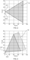
- Figures 2 and 3 each show a search area S1 or S2.
- the missiles AC1, AC2 fly at an altitude of 10 km and are 500 m apart on the Y-axis shown. For reasons of representation, the missiles AC1, AC2 can hardly be distinguished from one another.
- the numerical information is an example.
- the search area or the partial search areas are specified using the azimuth angle ⁇ (horizontal angle) and elevation angle ⁇ (vertical angle) and angular half-width ⁇ -S1, ⁇ -S2 for the azimuth angle and ⁇ -S1, ⁇ -S2 for the elevation angle.
- Such a search area is common to avoid collisions with other missiles.
- Such a search area represents a situation where the pilots have been informed that potentially threatening targets or objects are approaching.
- a corresponding device or system in the missile receives the information.
- the search area S1, S2 is to be searched within a total search time, with a given radar cross section ⁇ (in English: radar cross section) and range, with a detection probability PD being maximized.
- the search area S1 or S2 is divided into two partial search areas, which are searched cooperatively by the respective radar R of the two missiles AC1, AC2.
- the partial search areas do not have any overlap.
- Each partial search area has a detection probability.
- a division of the search area S1, S2 is to be found so that the detection probability PD_TS1, PD_TS2 for the two partial search areas TS1, TS2 for searching the search area S1, S2 is maximized.
- the detection probability PD_TS1, PD_TS2 is the same for the two partial search areas TS1, TS2.
- the total search time for searching through the search area S1, S2 is predetermined and can be specified or predefined.
- the method of dividing the search area S1 or S2 is run through for different combinations of two partial search areas TS1, TS2, and the detection probability PD when searching the search area S1 or S2 is determined.
- the azimuth angle range or the elevation angle range is changed in this example.
- Each missile AC1, AC2 searches the entire elevation range but only part of the azimuth range, or the entire azimuth range but only part of the elevation range.
- a different combination of the division can also be used as a basis.
- the detection probability PD, PD_TS1, PD_TS2 of the two partial search areas TS1, TS2 is determined for each combination.
- the combination of the two partial search areas TS1, TS2 for a maximum detection probability PD is then used for the subsequent search of the search area S1 or S2.
- the detection probability PD_TS1, PD_TS2 is the same for the two partial search areas TS1, TS2.
- the found geometric division according to a horizontal angle, vertical angle and distance, the maximum detection probability PD for an object or target, as well as the predetermined total search time leads to a reliable search of the search area S1 or S2 and thus to reliable situational image recognition. For example, an impending risk of collision can be avoided. It is also ensured that the search through the search area S1, S2 is completed within the total search time.
- FIG 4 and 5 show the division of the search area S1, S2 from the Figures 2, 3 into the two partial search areas TS1, TS2.
- Each partial search area TS1, TS2 is assigned to one of the missiles AC1, AC2 and is searched by the radar R of the respective missile AC1, AC2.
- FIG 4 a symmetrical division into the partial search areas TS1, TS2 can be seen. Such a division is intuitive and simple.
- the split ratio in terms of elevation is 25°/25° for the sub-search areas TS1, TS2.
- the search area S1 is as in figure 2 described.
- FIG 5 a division into the partial search areas TS1, TS2 can be seen.
- the split ratio in terms of elevation is 27.8°/22.2° for the sub-search areas TS1, TS2.
- the search area S2 is as in figure 3 described.
- the figures show when a search area is symmetrical about the antenna normal of the radar sensor (cf. 2 ) lies, a symmetrical division of the partial search areas TS1, TS2 leads to a maximum detection probability PD for targets or objects. If, on the other hand, the search area is not symmetrical, a symmetrical division leads to a detection probability PD that is smaller than the maximum detection probability PD.
- the division of the search area S1, S2 into the two partial search areas TS1, TS2 changes with the movement or the trajectory of the missile. In some examples, the division into the partial search areas TS1, TS2 is continuously adjusted.
- the method is carried out in a corresponding device, for example the missile AC1. Only the position of the other missile AC2 (cf. also figure 1 ) necessary. The latter then assigns the partial search area TS2 to be searched to the other missile AC2. For example, only the following values are transmitted to the other missile AC2: azimuth and elevation center line and the half width of the partial search range TS2 that is assigned to the other missile AC2. This creates a central control of the process.
- the missiles AC1, AC2 may define, independently of one another, the partial search area TS1, TS2 that is to be searched by the radar R of the missile AC1, AC2.
- a decentralized control is created by the independent assignment of the partial search area TS1, TS2 to be searched by the respective missile AC1, AC2.
- the missiles AC1, AC2 described are equipped accordingly for carrying out the method and for searching the search area.
- a missile also has a process unit for carrying out the method.
- FIG 12 shows searching of an area S in an airspace according to the prior art.
- the search is performed non-cooperatively.
- the areas A, B which are searched by the respective missile AC1, AC2, are divided up in such a way that these areas A, B largely overlap, as in figure 6 shown. This does not lead to a maximum probability of detection within a predetermined total search time for searching the area S and leads to less reliable situational image recognition.
Description
Die vorliegende Erfindung befasst sich mit einem Verfahren zum Durchsuchen eines Suchbereichs, einem Flugkörper und einer Flugkörperformation.The present invention relates to a method for searching a search area, a missile, and a missile formation.
Moderne Flugzeuge sind meist mit einer großen Anzahl an Sensoren ausgestattet, welche eine wichtige Rolle für das Flugzeug und/oder für den Piloten haben, um eine Mission mit bestmöglichem Ergebnis auszuführen.Modern aircraft are usually equipped with a large number of sensors, which play an important role for the aircraft and/or the pilot to carry out a mission with the best possible result.
Ein solcher Sensor ist beispielsweise ein Radar, welcher auch einer der meistverwendete Sensoren zur Lagebilderkennung ist. Mit einem Radar können Objekte oder Ziele bei großen Reichweiten erkannt oder detektiert werden. Die Eigenschaften eines Radars werden vom Wetter weniger beeinträchtigt, wie beispielsweise ein Kamerasensor. Ziel-Erkennung/Verfolgung mittels Radar ist beispielsweise auch dann noch möglich, wenn dies aufgrund von IMC (Instrument Metereological Conditions, deutsch Instrumentenflugbedingungen) mit bildgebenden elektro-optischen bzw. Infrarotsensoren nicht mehr möglich ist.Such a sensor is, for example, a radar, which is also one of the most commonly used sensors for situational image recognition. With a radar, objects or targets can be recognized or detected at long ranges. The characteristics of a radar are less affected by the weather, such as a camera sensor. Target detection/tracking using radar is still possible, for example, when this is no longer possible with imaging electro-optical or infrared sensors due to IMC (Instrument Meteorological Conditions).
Flugzeuge wurden oft mit mechanisch schwenkenden Radarantennen ausgestattet. Dies hatte zur Folge, dass das Durchsuchen eines Luftraums mit ein paar Parametern ausgeführt werden konnte, die optimierbar waren. Üblicherweise definiert der Pilot den Luftraum, der durchsucht werden soll, meist als Winkelangabe und Halbbreite, und die Reichweite innerhalb derer ein Ziel definierter Größe erkannt werden soll. Aufgrund dieser Informationen optimiert das Radar die dann ausgesandte Wellenform. Bei einer solchen Vorgehensweise ist das Suchmuster und das Abtasten des Luftraums weitestgehend festgelegt und hängt nur von der Größe des Luftraums ab, der durchsucht wird.Airplanes were often fitted with mechanically slewing radar antennas. As a result, searching an airspace could be performed with a few parameters that could be tuned. The pilot usually defines the airspace to be searched, usually in terms of angle and half-width, and the range within which a target of a defined size is to be detected. Because of With this information, the radar optimizes the waveform that is then sent out. In such an approach, the search pattern and airspace scanning is largely fixed and depends only on the size of the airspace being searched.
Die
Eine Aufgabe der vorliegenden Erfindung besteht nun darin, das Durchsuchen eines Luftraums so zu verbessern, dass eine schnelle und effiziente Lagebilderkennung, beispielsweise für einen Piloten, gewährleistet werden kann.An object of the present invention consists in improving the search of an airspace in such a way that rapid and efficient situational image recognition, for example for a pilot, can be guaranteed.
Diese Aufgabe wird durch ein Verfahren mit den Merkmalen des Anspruchs 1 gelöst.
Gemäß der Erfindung ist ein Verfahren zum Durchsuchen eines Suchbereichs angegeben, wobei jeweils wenigstens ein Radar in wenigstens zwei Flugkörpern angeordnet ist. Das Verfahren umfasst: a) Bestimmen einer vordefinierten Gesamtsuchzeit zum Durchsuchen des Suchbereichs, b) Aufteilen des Suchbereichs in wenigstens zwei Teilsuchbereiche, c) Durchsuchen der wenigstens zwei Teilsuchbereiche vom jeweiligen Radar der wenigstens zwei Flugkörper, wobei die wenigstens zwei Flugkörper das Durchsuchen kooperativ ausführen, wobei die Teilsuchbereiche so gewählt sind, dass eine Detektionswahrscheinlichkeit des Suchbereichs maximiert ist. Die Detektionswahrscheinlichkeit ist für die wenigstens zwei Teilsuchbereiche gleich. Die Teilsuchbereiche weisen im Wesentlichen keinen Überlapp auf. Das Aufteilen des Suchbereichs wird für verschiedene Kombinationen von jeweils zwei Teilsuchbereichen durchlaufen und die Detektionswahrscheinlichkeit wird beim Durchsuchen des Suchbereichs ermittelt. Für jede Kombination wird die Detektionswahrscheinlichkeit der zwei Teilsuchbereiche ermittelt. Die Kombination der zwei Teilsuchbereiche wird für eine maximale Detektionswahrscheinlichkeit für das dann folgende Durchsuchen des Suchbereichs verwendet.This object is achieved by a method having the features of
According to the invention, a method for searching a search area is specified, with at least one radar being arranged in at least two missiles. The method comprises: a) determining a predefined total search time for searching the search area, b) dividing the search area into at least two partial search areas, c) searching the at least two partial search areas by the respective radar of the at least two missiles, the at least two missiles carrying out the search cooperatively, wherein the partial search areas are selected in such a way that a detection probability of the search area is maximized. The detection probability is the same for the at least two partial search areas. The partial search areas essentially have no overlap. The search area is divided up for different combinations of two sub-search areas in each case, and the detection probability is determined when the search area is searched through. The detection probability of the two partial search areas is determined for each combination. The combination of the two partial search areas is used for a maximum detection probability for the subsequent search of the search area.
Ein Radar ist dazu eingerichtet verschiedene Objekte zu detektieren. Insbesondere kann das Radar das Durchsuchen eines Suchbereichs, welcher meist ein (Luft)Volumen ist, durchführen.A radar is set up to detect various objects. In particular, the radar can search a search area, which is mostly an (air) volume.
Gemäß der Erfindung wird ein Suchbereich in einer vorgegebenen Gesamtsuchzeit so durchsucht werden, dass die Detektionswahrscheinlichkeit für Objekte oder Ziele im Suchbereich maximal ist. Die Erfindung ermöglicht eine verbesserte Detektionswahrscheinlichkeit zum Auffinden von Zielen oder Objekten in einem dreidimensionalen Suchbereich innerhalb einer vorgegebenen Zeit. Es bleiben möglichst wenige oder keine Ziele oder Objekte undetektiert. Das Durchsuchen des Suchbereichs ist von höchster Bedeutung beispielsweise für die Lagebilderkennung durch einen Piloten. Undetektierte Objekte oder Ziele können nicht nur ein Problem werden wegen einer potentiellen Feindseligkeit während einer Mission, sondern auch wegen einer möglichen Kollisionsgefahr im Luftraum. Lagebilderkennung bezeichnet die Bestimmung des Ortes bzw. der Geschwindigkeit von anderen Zielen oder Objekten.According to the invention, a search area is searched in a predetermined total search time in such a way that the probability of detecting objects or targets in the search area is at a maximum. The invention enables an improved detection probability for finding targets or objects in a three-dimensional search area within a specified time. As few or no targets or objects as possible remain undetected. Searching the search area is of the utmost importance, for example for situational image recognition by a pilot. Undetected objects or targets can become a problem not only because of potential hostility during a mission, but also because of a possible risk of collision in airspace. Situation image recognition refers to the determination of the location or the speed of other targets or objects.
Radarsensoren, in diesem Text auch kurz Radar genannt, sind Sensoren welche der Flugkörper ggf. nebst weiteren Sensoren wie einer Kamera etc. aufweist. Ein solches Radar, kann mit aktiver elektronischer Ansteuerung der Einzelelemente des Radars ausgestattet sein (in Englisch: active electronically scanned array antennas (AESA)). Ein solches Radar kann den Radarstrahl nahezu instantan für verschiedene Raumwinkel steuern (ein Raumwinkel wird als Horizontal- und Vertikalwinkel angegeben, auch Azimut und Elevation genannt), so dass adaptives Strahlausrichten möglich ist.Radar sensors, also called radar for short in this text, are sensors which the missile may have along with other sensors such as a camera, etc. Such a radar can be equipped with active electronic control of the individual elements of the radar (in English: active electronically scanned array antennas (AESA)). Such a radar can steer the radar beam almost instantaneously for different solid angles (a solid angle is specified as horizontal and vertical angles, also called azimuth and elevation), so that adaptive beam pointing is possible.
Ein Flugkörper umfasst jegliche Art von fliegendem Gerät mit jeglicher Art von Antrieb. Beispielsweise, Flugzeuge, unbemannte Flugzeuge, in Englisch UAV ("unmanned aerial vehicle"), Drohnen, Lenkflugkörper, Raketen oder Helikopter.A missile includes any type of flying device with any type of propulsion. For example, airplanes, unmanned aircraft, in English UAV ("unmanned aerial vehicle"), drones, guided missiles, rockets or helicopters.
Der Suchaufwand ein Objekt oder Ziel im Suchbereich von zwei oder mehreren Flugkörpern zu detektieren, wird kooperativ durchgeführt. Das heißt, dass ein koordiniertes Durchsuchen des Suchbereichs stattfindet.The search effort to detect an object or target in the search area of two or more missiles is carried out cooperatively. This means that a coordinated search of the search area takes place.
Der Suchbereich ist ein (Luft)Volumen das vom wenigstens einem Radar des jeweiligen Flugkörpers erfasst werden kann. Der Suchbereich kann anhand von Horizontal-, Vertikalwinkel angegeben werden. Es ist auch möglich den Suchbereich anhand von dreidimensionalen Koordinaten anzugeben.The search area is an (air) volume that can be detected by at least one radar of the respective missile. The search area can be specified by horizontal, vertical angle. It is also possible to specify the search area using three-dimensional coordinates.
Oft befinden sich die Flugkörper in einer Flugformation im durchflogenen Luftraum. Der Suchbereich wird sich beispielsweise in der Umgebung von beiden Flugkörpern befinden. Bevorzugt wird sich der Suchbereich in Flugrichtung gesehen vor den Flugkörpern befinden.The missiles are often in a flight formation in the airspace flown through. For example, the search area will be in the vicinity of both missiles are located. The search area is preferably located in front of the missiles, viewed in the direction of flight.
Der zu durchsuchende Bereich im Luftraum, also der Suchbereich für die Flugkörper, wird in wenigstens zwei Teilsuchbereiche aufgeteilt. Die Anzahl der Teilsuchbereiche entspricht in manchen Beispielen der Erfindung der Anzahl der Flugkörper. Das Durchsuchen der wenigstens zwei Teilsuchbereiche erfolgt vom jeweiligen Radar des Flugkörpers, wobei jeweils ein Flugkörper wenigstens einen Teilsuchbereich durchsucht.The area in the airspace to be searched, ie the search area for the missiles, is divided into at least two partial search areas. In some examples of the invention, the number of partial search areas corresponds to the number of missiles. The at least two partial search areas are searched by the respective radar of the missile, with each missile searching at least one partial search area.
Das Durchsuchen der Teilsuchbereiche bzw. des Suchbereichs ist ein kooperatives Durchsuchen. Der Suchaufwand wird so verteilt, dass gleiche Bereiche des Suchbereichs nicht öfter durchsucht werden müssen. Bei zwei Flugkörpern mit jeweils einem Radar wird der Suchbereich beispielsweise in zwei Teilsuchbereiche aufgeteilt. Beide Flugkörper untersuchen zeitgleich oder im Wesentlichen zeitgleich ihren jeweiligen Teilsuchbereich. Das Verfahren wird, in manchen Beispielen, von sich in der Luft befindenden wenigstens zwei Flugkörpern durchgeführt.Searching through the partial search areas or the search area is a cooperative search. The search effort is distributed in such a way that the same areas of the search area do not have to be searched more often. In the case of two missiles, each with a radar, the search area is divided into two sub-search areas, for example. Both missiles examine their respective partial search area at the same time or essentially at the same time. The method is performed, in some examples, by airborne at least two missiles.
Die Teilsuchbereiche sind so gewählt, das eine Detektionswahrscheinlichkeit maximiert ist. Damit ist gewährleistet, dass die beste Aufteilung des Suchbereichs gefunden wird und dass ein mehrfaches Durchsuchen des gleichen Bereichs entfällt. Der Suchbereich wird in der vorgegebenen Gesamtsuchzeit durchsucht. Beispielsweise kann die Detektionswahrscheinlichkeit für verschiedene Aufteilungen des Suchbereichs in Teilsuchbereiche bei vorgegebener Gesamtsuchzeit maximiert werden. Für eine bestimmte Aufteilung des Suchbereichs in Teilsuchbereiche ist die Detektionswahrscheinlichkeit maximal.The partial search areas are selected in such a way that the detection probability is maximized. This ensures that the best division of the search area is found and that multiple searches of the same area are avoided. The search area is searched in the specified total search time. For example, the probability of detection can be maximized for different subdivisions of the search area into sub-search areas for a given total search time. The probability of detection is maximum for a specific division of the search area into sub-search areas.
Mit dem erfindungsgemäßen Verfahren kann vermieden werden, dass sich nach dem Durchsuchen undektierte Ziele oder Objekte im Suchbereich befinden, welche beispielsweise auftreten, wenn der Suchbereich in einer naiven Weise, beispielsweise zu gleichen Teilen, aufgeteilt wird. Dies gilt insbesondere, wenn sich der Suchbereich bei beliebigen Horizontal- und Vertikalwinkeln im Luftraum erstreckt.The method according to the invention can be used to avoid undefected targets or objects being located in the search area after the search, which can occur, for example, if the search area is divided up in a naive manner, for example in equal parts. This is especially true when the search area extends at any horizontal and vertical angles in airspace.
In manchen Beispielen des Verfahrens ist die Gesamtsuchzeit die kooperative Gesamtsuchzeit, die von den wenigstens zwei Flugkörpern benötigt wird um den Suchbereich zu durchsuchen. Die Suchzeit ist die Zeit, die der Radarstrahl benötigt um den Teilsuchbereich auszuleuchten und das Echo zu empfangen. In manchen Beispielen wird auch die Zeit mitberücksichtigt werden, welche benötigt wird um das empfangene Signal (Echo) zu bearbeiten um Objekte oder Ziele zu entdecken.In some examples of the method, the total search time is the cooperative total search time required by the at least two missiles to search the search area. The search time is the time that the radar beam needs to illuminate the partial search area and to receive the echo. In some examples, the time required to process the received signal (echo) to detect objects or targets will also be taken into account.
Gemäß einem Beispiel wird die Detektionswahrscheinlichkeit abhängig von einem Objekt von vorgegebener Größe bei vorgegebener Entfernung maximiert. Die Größe und/oder die Entfernung ist in manchen Beispielen vorbestimmt. Dies ermöglicht eine maximale Detektionswahrscheinlichkeit für verschiedene Objekte bei verschiedenen Entfernungen.According to one example, the probability of detection is maximized depending on an object of a given size at a given distance. The size and/or distance is predetermined in some examples. This enables a maximum probability of detection for different objects at different distances.
Gemäß der Erfindung ist die Detektionswahrscheinlichkeit für die wenigstens zwei Teilsuchbereiche gleich. Eine optimale Aufteilung der Teilsuchbereiche ergibt sich bei gleicher Detektionswahrscheinlichkeit für die wenigstens zwei Teilsuchbereiche. Die Aufteilung der Teilsuchbereiche wird so gewählt, dass die Detektionswahrscheinlichkeit des Suchbereichs maximiert ist. Die Teilsuchbereiche sind dabei voneinander verschieden, beispielweise sind die Teilsuchbereiche räumlich voneinander unterschiedlich. Beispielsweise ist die Größe der Teilsuchbereiche voneinander verschieden. Wird die Detektionswahrscheinlichkeit in einem Teilbereich erhöht, sinkt gleichzeitig die Detektionswahrscheinlichkeit in dem wenigstens einen anderen Teilsuchbereich.According to the invention, the probability of detection is the same for the at least two partial search areas. An optimal division of the sub-search areas results with the same detection probability for the at least two sub-search areas. The partial search areas are divided up in such a way that the detection probability of the search area is maximized. The partial search areas are different from one another, for example the partial search areas are spatially different from one another. For example, the size of the partial search areas is different from each other. If the probability of detection in a partial area is increased, the probability of detection in the at least one other partial search area decreases at the same time.
Gemäß der Erfindung ist die Gesamtsuchzeit vordefiniert. Beispielsweise kann der Pilot die Gesamtsuchzeit vorgeben. Gegebenenfalls kann die Gesamtsuchzeit geändert oder an die jeweilige Lagebilderkennung angepasst werden.According to the invention, the total search time is predefined. For example, the pilot can specify the total search time. If necessary, the total search time can be changed or adapted to the respective situational image recognition.
Gemäß der Erfindung weisen die Teilsuchbereiche im Wesentlichen keinen Überlapp auf. In manchen Beispielen weisen die Teilsuchbereiche keinen Überlapp auf. Damit wird die Koordinierung des Durchsuchens einfacher und der Kommunikationsbedarf zwischen den Flugkörpern ist niedrig. Es gibt Beispiele, in denen die Teilsuchbereiche minimal überlappen. Durch einen minimalen oder überhaupt keinen Überlapp wird mehrmaliges Durchsuchen eines (Teil)Bereichs vermieden und der Suchaufwand zum Durchsuchen eines Suchbereichs kann geringgehalten werden. Auch werden Lücken im Suchbereich vermieden bei gleichzeitig maximaler Detektionswahrscheinlichkeit für Ziele oder Objekte im Suchbereich.According to the invention, the partial search areas essentially have no overlap. In some examples, the sub-search areas do not have an overlap. This makes the coordination of the search easier and the need for communication between the missiles is low. There are examples where the sub-search areas overlap minimally. A minimal overlap or no overlap at all avoids multiple searches of a (partial) area and the search effort for searching a search area can be kept low. Gaps in the search area are also avoided while at the same time there is maximum detection probability for targets or objects in the search area.
Gemäß einem Beispiel ist der Suchbereich vorgebbar oder veränderbar. Beispielsweise kann der Pilot den Suchbereich vorgeben durch einstellen eines Horizontal- bzw. Vertikalwinkels und der dazugehörigen (Halb)Breite (auch als (Halb)Breite in Azimut und Elevation bezeichnet). Gegebenenfalls kann der Suchbereich an die jeweilige Lagebilderkennung angepasst werden. In manchen Beispielen ist der Suchbereich vordefiniert.According to one example, the search area can be specified or changed. For example, the pilot can specify the search area by setting a horizontal or vertical angle and the associated (half) width (also referred to as (half) width in azimuth and elevation). If necessary, the search area can be adapted to the respective situational image recognition. In some examples, the search area is predefined.
Gemäß einem Beispiel ändert sich das Aufteilen des Suchbereichs in Teilsuchbereiche entsprechend der Bewegung und/oder der Trajektorie der wenigstens zwei Flugkörper.According to one example, the division of the search area into partial search areas changes according to the movement and/or the trajectory of the at least two missiles.
Gemäß einem Beispiel wird das Aufteilen des Suchbereichs in Teilsuchbereiche entsprechend der Bewegung und/oder der Trajektorie der wenigstens zwei Flugkörper fortlaufend angepasst. Der Suchbereich ist beispielsweise mittels dreidimensionalen Koordinaten vorgegeben. Die Flugkörper bewegen sich im Suchbereich, so dass sich der Horizontal- und Vertikalwinkel (Azimut- und Elevationswinkel) und deren Winkelbreiten ändern.According to one example, the division of the search area into partial search areas is continuously adjusted according to the movement and/or the trajectory of the at least two missiles. The search area is specified, for example, using three-dimensional coordinates. The missiles move in the search area so that the horizontal and vertical angles (azimuth and elevation angles) and their angular widths change.
Gemäß einem Beispiel wird ein Teilsuchbereich gemäß eines Horizontalwinkels, eines Vertikalwinkels und dazugehörigen Winkelbreiten, oder gemäß dreidimensionaler Koordinaten bestimmt. Auch können alle Teilsuchereiche anhand von Horizontalwinkel, Vertikalwinkel bestimmt werden. In manchen Beispielen ist die Bestimmung des einen oder der mehreren Teilsuchbereiche mittels dreidimensionalen Koordinaten möglich, beispielsweise werden die Eckpunkte oder die Flächen des Teilsuchbereichs angegeben.According to an example, a partial search area is determined according to a horizontal angle, a vertical angle and associated angular widths, or according to three-dimensional coordinates. All partial search areas can also be determined using horizontal angles and vertical angles. In some examples, it is possible to determine the one or more partial search areas using three-dimensional coordinates, for example the corner points or the areas of the partial search area are specified.
Gemäß einem Beispiel weist einer der wenigstens zwei Flugkörper den zu durchsuchenden Teilsuchbereich dem wenigstens einen anderen Flugkörper zu. Damit kann eine zentrale Steuerung des Verfahrens geschaffen werden (zentralisiertes Verfahren). Die Zuweisung kann von jedem der Flugkörper ausgeführt werden. In manchen Beispielen ist einer der Flugkörper dazu ausgewiesen. Durch eine zentrale Steuerung kann der Suchaufwand optimiert werden.According to one example, one of the at least two missiles assigns the sub-search area to be searched to the at least one other missile. This allows the process to be controlled centrally (centralized process). The assignment can be performed by any of the missiles. In some examples, one of the missiles is designated as such. The search effort can be optimized through central control.
Gemäß einem Beispiel legen die wenigstens zwei Flugkörper unabhängig voneinander jeweils den Teilsuchbereich fest, der vom Radar des Flugkörpers durchsucht werden soll. Durch das unabhängige Zuweisen des zu durchsuchenden Bereichs durch den jeweiligen Flugkörper wird eine dezentrale Steuerung geschaffen (dezentralisiertes Verfahren). Der zu durchsuchende Bereich, den der einzelne Flugkörper sich selber zuweist kann mit dem Teilbereich identisch sein, wenn der Suchbereich von einem Flugkörper anhand einer zentralen Steuerung in verschiedene Teilsuchbereiche ausgeführt wird.According to one example, the at least two missiles each independently determine the sub-search area to be searched by the missile's radar. By independently assigning the area to be searched by the respective missile, a decentralized control is created (decentralized method). The area to be searched, which the individual missile allocates to itself, can be identical to the sub-area if the search area is carried out by a missile using a central controller in different sub-search areas.
Gemäß einem Beispiel ist ein vollständiges Durchsuchen des Suchbereichs gewährleistet. Mit anderen Worten, das Durchsuchen des Suchbereichs wird in der Gesamtsuchzeit abgeschlossen mit einer maximalen Detektionswahrscheinlichkeit.According to one example, a full search of the search area is guaranteed. In other words, the search of the search area is completed in the total search time with a maximum probability of detection.
Gemäß einem Aspekt der Erfindung ist ein Flugkörper vorgesehen, der wenigstens ein Radar und eine Prozesseinheit umfasst. Die Prozesseinheit ist dazu eingerichtet, das erfindungsgemäße Verfahren durchzuführen.According to one aspect of the invention, a missile is provided that includes at least one radar and one processing unit. The process unit is set up to carry out the method according to the invention.
Gemäß einem Aspekt der Erfindung ist eine Flugkörperformation vorgesehen, welche wenigstens zwei Flugkörper umfasst, wobei die Flugkörperformation dazu eingerichtet ist, einen Suchbereich in einem Luftraum zu erfassen.According to one aspect of the invention, a missile formation is provided which comprises at least two missiles, the missile formation being set up to cover a search area in an airspace.
Gemäß einem Aspekt der Erfindung ist das koordinierte Durchsuchen eines Suchbereichs mit wenigstens zwei Flugkörpern, in welchen jeweils wenigstens ein Radar angeordnet ist, von großem Nutzen. Insbesondere ergibt sich durch das Verfahren eine Zeitersparnis beim Durchsuchen eines 3-dimensionalen Suchbereichs. Wenn der Suchbereich bei beliebig vorgegebenen Azimut- und Elevationswinkeln (Horizontal- und Vertikalwinkel) und den dazugehörigen Winkelbreiten liegt, dann führt eine einfache Aufteilung des Suchbereichs wie im Stand der Technik, beispielsweise ein Halbieren des Suchbereichs, zu signifikanten Zeitverzögerungen in der Gesamtsuchzeit. Derartige Zeitverzögerungen sind beim erfindungsgemäßen Verfahren nahezu ausgeschlossen. Die Teilsuchbereiche überlappen nicht (minimale Überlappung der Teilsuchbereiche, beispielsweise eine gemeinsame Grenze der Teilsuchbereiche können in manchen Beispielen vorhanden sein). Das Verfahren teilt den Suchbereich in die bestmöglichen Teilbereiche auf, so dass die Gesamtsuchzeit, welche zum kooperativen Durchsuchen des Suchbereichs benötigt wird, um eine gewünschte Detektionswahrscheinlichkeit zu gewährleisten, minimal ist. Mit anderen Worten, die Zeit die benötigt wird um einen Suchbereich zu durchsuchen, wird minimiert, wobei eine minimale Detektionswahrscheinlichkeit für Ziele oder Objekte vorbestimmter Größe bei einer vorbestimmten Entfernung gewährleistet wird. Eine Zeitersparnis zum Durchsuchen eines dreidimensionalen Volumens, welches vom Piloten vorgegeben werden kann, ist das Ergebnis. Dies führt insbesondere bei einem beliebig vorgegebenen Suchbereich, zu einem effektiveren und vor allem deutlich schnelleren Durchsuchen.According to one aspect of the invention, the coordinated search of a search area with at least two missiles, in each of which at least one radar is arranged, is of great benefit. In particular, the method saves time when searching through a 3-dimensional search area. If the search area is at any specified azimuth and elevation angles (horizontal and vertical angles) and the associated angular widths, then a simple division of the search area as in the prior art, for example halving the search area, leads to significant time delays in the total search time. Such time delays are almost impossible with the method according to the invention. The sub-search areas do not overlap (minimal overlap of the sub-search areas, e.g. a common boundary of the sub-search areas, may exist in some examples). The method divides the search area into the best possible sub-areas, so that the total search time required for cooperatively searching the search area in order to ensure a desired probability of detection is minimal. In other words, the time it takes to search a search area is minimized, while ensuring a minimum probability of detection for targets or objects of a predetermined size at a predetermined distance. The result is a time saving for searching a three-dimensional volume, which can be specified by the pilot. This leads to a more effective and, above all, significantly faster search, especially in the case of an arbitrarily specified search area.
Es sei darauf hingewiesen, dass die Merkmale der Ausführungsbeispiele des Verfahrens auch für Ausführungsformen des Flugkörpers sowie der Flugkörperformation gelten und umgekehrt. Außerdem können auch diejenigen Merkmale frei miteinander kombiniert werden, bei denen dies nicht explizit erwähnt ist.It should be pointed out that the features of the exemplary embodiments of the method also apply to embodiments of the missile and the missile formation and vice versa. In addition, those features can also be freely combined with one another where this is not explicitly mentioned.
Diese und weitere Aspekte der Erfindung werden unter Bezugnahme und mit Verweis auf die folgenden Ausführungen ersichtlich.These and other aspects of the invention will become apparent upon reference and reference to the following disclosure.
Nachfolgend wird anhand der beigefügten Zeichnungen näher auf Ausführungsbeispiele der Erfindung eingegangen. Es zeigen:
- Fig. 1
- zeigt skizzenhaft zwei Flugkörper und einen Suchbereich;
- Fig. 2.
- zeigt beispielhaft einen zu durchsuchenden Suchbereich in einem Koordinatensystem;
- Fig. 3
- zeigt beispielhaft einen zu durchsuchenden Suchbereich in einem Koordinatensystem;
- Fig. 4
- zeigt die Aufteilung des Suchbereichs
S1 aus Figur 2 in jeweils zwei Teilsuchbereiche TS1, TS2; - Fig. 5
- zeigt die Aufteilung des Suchbereichs S2 aus
Figuren 3 in jeweils zwei Teilsuchbereiche TS1, TS2; - Fig. 6
- zeigt ein Beispiel nach dem Stand der Technik.
- 1
- shows a sketch of two missiles and a search area;
- 2
- shows an example of a search area to be searched in a coordinate system;
- 3
- shows an example of a search area to be searched in a coordinate system;
- 4
- shows the division of the search area S1
figure 2 in two partial search areas TS1, TS2; - figure 5
- shows the division of the search area S2
Figures 3 in two partial search areas TS1, TS2; - 6
- shows an example according to the prior art.
Der Suchbereich S teilt sich auf in zwei Teilsuchbereiche TS1, TS2 die vom Radar R des jeweiligen Flugkörpers AC1, AC2 durchsucht werden. Die Teilsuchbereiche TS1, TS2 haben keinen Überlapp. Das Durchsuchen der Teilbereiche TS1, TS2 wird kooperativ ausgeführt. Wie in den folgenden Figuren beschrieben, umfassen die Teilsuchbereiche TS1, TS2 den gesamten Suchbereich S.The search area S is divided into two partial search areas TS1, TS2, which are searched by the radar R of the respective missile AC1, AC2. The partial search areas TS1, TS2 do not overlap. The searching of the partial areas TS1, TS2 is carried out cooperatively. As described in the following figures, the partial search areas TS1, TS2 encompass the entire search area S.
In
In
In beiden
In diesem Ausführungsbeispiel, soll also eine Aufteilung des Suchbereichs S1, S2 gefunden werden, so dass die Detektionswahrscheinlichkeit PD_TS1, PD_TS2 für die zwei Teilsuchbereiche TS1, TS2 zum Durchsuchen des Suchbereichs S1, S2 maximiert ist. Optimalerweise ist die Detektionswahrscheinlichkeit PD_TS1, PD_TS2 für die zwei Teilsuchbereiche TS1, TS2 gleich. Dabei ist die Gesamtsuchzeit zum Durchsuchen des Suchbereichs S1, S2 vorbestimmt und kann vorgegeben oder vordefiniert sein.In this exemplary embodiment, a division of the search area S1, S2 is to be found so that the detection probability PD_TS1, PD_TS2 for the two partial search areas TS1, TS2 for searching the search area S1, S2 is maximized. Optimally, the detection probability PD_TS1, PD_TS2 is the same for the two partial search areas TS1, TS2. The total search time for searching through the search area S1, S2 is predetermined and can be specified or predefined.
Das Verfahren der Aufteilung des Suchbereichs S1 oder S2 wird für verschiedene Kombinationen von jeweils zwei Teilsuchbereichen TS1, TS2 durchlaufen und die Detektionswahrscheinlichkeit PD beim Durchsuchen des Suchbereichs S1 oder S2 wird ermittelt. Um die beste Aufteilung des Suchbereichs S1, S2 zu erhalten wird in diesem Beispiel jeweils der Azimutwinkelbereich oder der Elevationswinkelbereich verändert. Jeder Flugkörper AC1, AC2 durchsucht den gesamten Elevationsbereich aber nur einen Teil des Azimutbereichs, oder den gesamten Azimutbereich aber nur einen Teil des Elevationsbereichs. In anderen Beispielen kann auch eine andere Kombination der Aufteilung zugrunde gelegt werden.The method of dividing the search area S1 or S2 is run through for different combinations of two partial search areas TS1, TS2, and the detection probability PD when searching the search area S1 or S2 is determined. In order to obtain the best division of the search area S1, S2, the azimuth angle range or the elevation angle range is changed in this example. Each missile AC1, AC2 searches the entire elevation range but only part of the azimuth range, or the entire azimuth range but only part of the elevation range. In other examples, a different combination of the division can also be used as a basis.
Für jede Kombination wird die Detektionswahrscheinlichkeit PD, PD_TS1, PD_TS2 der zwei Teilsuchbereiche TS1, TS2 ermittelt. Die Kombination der zwei Teilsuchbereiche TS1, TS2 für eine maximale Detektionswahrscheinlichkeit PD wird für das dann folgende Durchsuchen des Suchbereichs S1 oder S2 verwendet. In diesem Ausführungsbeispiel ist die Detektionswahrscheinlichkeit PD_TS1, PD_TS2 für die zwei Teilsuchbereiche TS1, TS2 gleich.The detection probability PD, PD_TS1, PD_TS2 of the two partial search areas TS1, TS2 is determined for each combination. The combination of the two partial search areas TS1, TS2 for a maximum detection probability PD is then used for the subsequent search of the search area S1 or S2. In this exemplary embodiment, the detection probability PD_TS1, PD_TS2 is the same for the two partial search areas TS1, TS2.
In diesem Beispiel führt die gefundene geometrische Aufteilung gemäß eines Horizontalwinkels, Vertikalwinkels und einer Entfernung, die maximale Detektionswahrscheinlichkeit PD für ein Objekt oder Ziel, als auch die vorbestimmte Gesamtsuchzeit zu einem zuverlässigen Durchsuchen des Suchbereichs S1 oder S2 und damit zu einer zuverlässigen Lagebilderkennung. Beispielsweise kann eine drohende Kollisionsgefahr vermieden werden. Es ist auch gewährleistet, dass das Durchsuchen des Suchbereichs S1, S2 innerhalb der Gesamtsuchzeit vollständig abgeschlossen wird.In this example, the found geometric division according to a horizontal angle, vertical angle and distance, the maximum detection probability PD for an object or target, as well as the predetermined total search time leads to a reliable search of the search area S1 or S2 and thus to reliable situational image recognition. For example, an impending risk of collision can be avoided. It is also ensured that the search through the search area S1, S2 is completed within the total search time.
In
In
Die Figuren zeigen, wenn ein Suchbereich symmetrisch um die Antennennormale des Radarsensors (vgl.
In manchen Ausführungsformen wird das Verfahren in einer entsprechenden Vorrichtung beispielsweise des Flugkörper AC1 durchgeführt. Dazu ist nur die Position des anderen Flugkörpers AC2 (vgl. auch
Es ist jedoch auch möglich, dass die Flugkörper AC1, AC2 unabhängig voneinander jeweils den Teilsuchbereich TS1, TS2 festlegen, der vom Radar R des Flugkörpers AC1, AC2 durchsucht werden soll. Durch das unabhängige Zuweisen des zu durchsuchenden Teilsuchbereichs TS1, TS2 durch den jeweiligen Flugkörper AC1, AC2 wird eine dezentrale Steuerung geschaffen.However, it is also possible for the missiles AC1, AC2 to define, independently of one another, the partial search area TS1, TS2 that is to be searched by the radar R of the missile AC1, AC2. A decentralized control is created by the independent assignment of the partial search area TS1, TS2 to be searched by the respective missile AC1, AC2.
Die beschriebenen Flugkörper AC1, AC2 sind zum Durchführen des Verfahrens und zum Durchsuchen des Suchbereichs entsprechend ausgestattet. Beispielsweise weist ein solcher Flugkörper auch eine Prozesseinheit zum Durchführen des Verfahrens auf.The missiles AC1, AC2 described are equipped accordingly for carrying out the method and for searching the search area. For example, such a missile also has a process unit for carrying out the method.
Die oberhalb beschriebenen Ausführungsbeispiele können in unterschiedlicher Art und Weise kombiniert werden. Insbesondere können auch Aspekte des Verfahrens für Ausführungsformen der Vorrichtungen sowie Verwendung der Vorrichtungen verwendet werden und umgekehrt. Die Darstellungen in den Figuren sind schematisch und nicht maßstäblich. Werden in der folgenden Figurenbeschreibung in verschiedenen Figuren die gleichen Bezugszeichen verwendet, so bezeichnen diese gleiche oder ähnliche Elemente. Gleiche oder ähnliche Elemente können aber auch durch unterschiedliche Bezugszeichen bezeichnet sein.The exemplary embodiments described above can be combined in different ways. In particular, aspects of the method for embodiments of the devices and use of the devices can also be used and vice versa. The representations in the figures are schematic and not to scale. If the same reference symbols are used in different figures in the following description of the figures, then these denote the same or similar elements. However, the same or similar elements can also be denoted by different reference symbols.
Ergänzend ist darauf hinzuweisen, dass "umfassend" keine anderen Elemente oder Schritte ausschließt und "eine" oder "ein" keine Vielzahl ausschließt. Ferner sei darauf hingewiesen, dass Merkmale oder Schritte, die mit Verweis auf eines der obigen Ausführungsbeispiele beschrieben worden sind, auch in Kombination mit anderen Merkmalen oder Schritten anderer oben beschriebener Ausführungsbeispiele verwendet werden können. Bezugszeichen in den Ansprüchen sind nicht als Einschränkung anzusehen.In addition, it should be noted that "comprising" does not exclude other elements or steps, and "a" or "an" does not exclude a plurality. Furthermore, it should be pointed out that features or steps that have been described with reference to one of the above exemplary embodiments can also be used in combination with other features or steps of other exemplary embodiments described above. Any reference signs in the claims should not be construed as limiting.
Claims (9)
- Method for searching a search area (S), wherein in each case at least one radar (R) is arranged in at least two missiles (AC1, AC2), comprising:a) determining a total search time for searching the search area (S),b) splitting the search area (S) into at least two search subareas (TS1, TS2),c) searching the at least two search subareas (TS1, TS2) by means of the respective radar (R) of the at least two missiles (AC1, AC2), wherein the at least two missiles (AC1, AC2) carry out the searching cooperatively, wherein the search subareas (TS1, TS2) are chosen such that a detection probability (PD) of the search area (S) is maximized;wherein the detection probability for the at least two search subareas (TS1, TS2) is the same;wherein the search subareas (TS1, TS2) have substantially no overlap;wherein the splitting of the search area (S) is performed for different combinations of in each case two search subareas (TS1, TS2) and the detection probability (PD) for searching the search area (S) is ascertained;wherein, for each combination, the detection probability (PD) of the two search subareas (TS1, TS2) is ascertained;wherein the combination of the two search subareas (TS1, TS2) for a maximum detection probability (PD) is used for the searching of the search area (S).
- Method according to Claim 1, wherein the detection probability is maximized on the basis of an object of prescribed size at a prescribed distance.
- Method according to one of the preceding claims, wherein the search area (S) is prescribable or alterable.
- Method according to one of the preceding claims, wherein the splitting of the search area (S) into search subareas (TS1, TS2) changes according to the movement and/or the trajectory of the at least two missiles (AC1, AC2) .
- Method according to one of the preceding claims, wherein the splitting of the search area (S) into search subareas (TS1, TS2) is continually adapted according to the movement and/or the trajectory of the at least two missiles (AC1, AC2).
- Method according to one of the preceding claims, wherein a search subarea (TS1, TS2) is determined based on a horizontal angle, a vertical angle and associated angle widths, or based on three-dimensional coordinates.
- Method according to one of the preceding claims, wherein one of the at least two missiles (AC1, AC2) assigns the search subarea (TS1, TS2) to be searched to the at least one other missile.
- Method according to one of the preceding claims, wherein the at least two missiles (AC1, AC2) each independently of one another stipulate the search subarea (TS1, TS2) that is supposed to be searched by the radar (R) of the missile.
- Method according to one of the preceding claims, wherein complete searching of the search area (S) is ensured.
Applications Claiming Priority (1)
| Application Number | Priority Date | Filing Date | Title |
|---|---|---|---|
| DE102018121821.4A DE102018121821A1 (en) | 2018-09-07 | 2018-09-07 | Coordinated detection of objects in an air space |
Publications (2)
| Publication Number | Publication Date |
|---|---|
| EP3620819A1 EP3620819A1 (en) | 2020-03-11 |
| EP3620819B1 true EP3620819B1 (en) | 2023-08-30 |
Family
ID=67437927
Family Applications (1)
| Application Number | Title | Priority Date | Filing Date |
|---|---|---|---|
| EP19186908.0A Active EP3620819B1 (en) | 2018-09-07 | 2019-07-18 | Coordinated detection of objects in an airspace |
Country Status (4)
| Country | Link |
|---|---|
| US (1) | US11320532B2 (en) |
| EP (1) | EP3620819B1 (en) |
| JP (1) | JP7095831B2 (en) |
| DE (1) | DE102018121821A1 (en) |
Families Citing this family (4)
| Publication number | Priority date | Publication date | Assignee | Title |
|---|---|---|---|---|
| CN113108653B (en) * | 2021-04-21 | 2022-02-22 | 中国人民解放军军事科学院国防科技创新研究院 | Missile cluster intelligent cooperation system and implementation method thereof |
| CN113391274B (en) * | 2021-06-15 | 2022-08-05 | 电子科技大学 | Low-altitude target optimal search method for airborne phased array radar |
| CN113359849B (en) * | 2021-07-06 | 2022-04-19 | 北京理工大学 | Multi-unmanned aerial vehicle collaborative rapid search method for moving target |
| CN114428514B (en) * | 2022-01-20 | 2023-01-17 | 北京理工大学 | Heterogeneous fine guidance bullet group cooperative detection method |
Family Cites Families (9)
| Publication number | Priority date | Publication date | Assignee | Title |
|---|---|---|---|---|
| US3858206A (en) * | 1973-02-05 | 1974-12-31 | Hughes Aircraft Co | Method and means for operating an airborne switched array radar system |
| US6690318B1 (en) * | 2002-12-27 | 2004-02-10 | General Atomics | Cellular radar |
| US7123169B2 (en) * | 2004-11-16 | 2006-10-17 | Northrop Grumman Corporation | Method and apparatus for collaborative aggregate situation awareness |
| JP4772069B2 (en) | 2008-02-19 | 2011-09-14 | 三菱電機株式会社 | Sensor control system |
| EP2428814A1 (en) | 2010-09-13 | 2012-03-14 | France Telecom | Object detection method, device and system |
| US8854255B1 (en) * | 2011-03-28 | 2014-10-07 | Lockheed Martin Corporation | Ground moving target indicating radar |
| US9501055B2 (en) * | 2012-03-02 | 2016-11-22 | Orbital Atk, Inc. | Methods and apparatuses for engagement management of aerial threats |
| JP6679357B2 (en) | 2016-03-17 | 2020-04-15 | セコム株式会社 | Flying object monitoring system |
| DE102018114109A1 (en) * | 2018-06-13 | 2019-12-19 | Airbus Defence and Space GmbH | Coordinated airspace search |
-
2018
- 2018-09-07 DE DE102018121821.4A patent/DE102018121821A1/en active Pending
-
2019
- 2019-07-18 EP EP19186908.0A patent/EP3620819B1/en active Active
- 2019-07-19 US US16/517,170 patent/US11320532B2/en active Active
- 2019-07-26 JP JP2019138279A patent/JP7095831B2/en active Active
Also Published As
| Publication number | Publication date |
|---|---|
| DE102018121821A1 (en) | 2020-03-12 |
| JP7095831B2 (en) | 2022-07-05 |
| US11320532B2 (en) | 2022-05-03 |
| EP3620819A1 (en) | 2020-03-11 |
| JP2020041795A (en) | 2020-03-19 |
| US20200081115A1 (en) | 2020-03-12 |
Similar Documents
| Publication | Publication Date | Title |
|---|---|---|
| EP3620819B1 (en) | Coordinated detection of objects in an airspace | |
| DE102017217961B4 (en) | DEVICE FOR CONTROLLING A VEHICLE AT AN INTERSECTION | |
| DE102011101049B4 (en) | Sensor and alignment adjustment method | |
| EP2981786B1 (en) | Control of an image triggering system for taking aerial photographs in nadir alignment for an unmanned aircraft | |
| DE4244001A1 (en) | ||
| EP0886847A1 (en) | Method of detecting a collision risk and preventing air collisions | |
| DE102018129253A1 (en) | Methods and apparatus for reducing depth map size in collision avoidance systems | |
| EP2131210B1 (en) | Method for optimising the operation of an active side view sensor at varying heights above the surface to be recorded | |
| DE102020105642A1 (en) | DESIGN AND PROCESSING WITH ANTENNA ARRAYS TO ELIMINATE MALDETECTIONS IN A RADAR SYSTEM | |
| DE10120536A1 (en) | Modified ROSAR process | |
| EP3584600A1 (en) | Coordinated searching of airspace | |
| EP2920606A1 (en) | Apparatus and method for determining the elevation angle in a radar system | |
| WO2020127245A1 (en) | Determining the orientation of objects by means of radar or through the use of electromagnetic interrogation radiation | |
| DE102018128738A1 (en) | METHOD AND DEVICE FOR CONTINUOUS TRACKING IN A MULTI-RADAR SYSTEM | |
| DE102018106478A1 (en) | TARGET TRACKING USING REGIONAL COVENANT | |
| DE10341893A1 (en) | Method for reducing Doppler in a coherent pulsed radar system | |
| EP3404443B1 (en) | Device and method for detecting a traffic participant | |
| DE202019102395U1 (en) | Object position detection device and drone | |
| DE102016224962B3 (en) | Synthetic aperture radar method and synthetic aperture radar system | |
| DE102019213927A1 (en) | Grid-based delineator classification | |
| DE1548415B2 (en) | LOCATION AND GUIDANCE PROCEDURES FOR AIRCRAFT | |
| DE102013013123B4 (en) | Method and device for locating radio stations by means of Doppler effect on board flying platforms | |
| DE102012006784B4 (en) | Device and method for locating radio signals by means of Doppler effect on board flying platforms | |
| DE102016012513B3 (en) | Method and device for determining a direction of movement and speed of a moving emitter | |
| DE102022128004A1 (en) | Method for operating a radar system, radar system, driver assistance system and vehicle |
Legal Events
| Date | Code | Title | Description |
|---|---|---|---|
| PUAI | Public reference made under article 153(3) epc to a published international application that has entered the european phase |
Free format text: ORIGINAL CODE: 0009012 |
|
| STAA | Information on the status of an ep patent application or granted ep patent |
Free format text: STATUS: THE APPLICATION HAS BEEN PUBLISHED |
|
| AK | Designated contracting states |
Kind code of ref document: A1 Designated state(s): AL AT BE BG CH CY CZ DE DK EE ES FI FR GB GR HR HU IE IS IT LI LT LU LV MC MK MT NL NO PL PT RO RS SE SI SK SM TR |
|
| AX | Request for extension of the european patent |
Extension state: BA ME |
|
| STAA | Information on the status of an ep patent application or granted ep patent |
Free format text: STATUS: REQUEST FOR EXAMINATION WAS MADE |
|
| 17P | Request for examination filed |
Effective date: 20200911 |
|
| RBV | Designated contracting states (corrected) |
Designated state(s): AL AT BE BG CH CY CZ DE DK EE ES FI FR GB GR HR HU IE IS IT LI LT LU LV MC MK MT NL NO PL PT RO RS SE SI SK SM TR |
|
| STAA | Information on the status of an ep patent application or granted ep patent |
Free format text: STATUS: EXAMINATION IS IN PROGRESS |
|
| 17Q | First examination report despatched |
Effective date: 20210706 |
|
| GRAP | Despatch of communication of intention to grant a patent |
Free format text: ORIGINAL CODE: EPIDOSNIGR1 |
|
| STAA | Information on the status of an ep patent application or granted ep patent |
Free format text: STATUS: GRANT OF PATENT IS INTENDED |
|
| INTG | Intention to grant announced |
Effective date: 20230322 |
|
| GRAS | Grant fee paid |
Free format text: ORIGINAL CODE: EPIDOSNIGR3 |
|
| GRAA | (expected) grant |
Free format text: ORIGINAL CODE: 0009210 |
|
| STAA | Information on the status of an ep patent application or granted ep patent |
Free format text: STATUS: THE PATENT HAS BEEN GRANTED |
|
| AK | Designated contracting states |
Kind code of ref document: B1 Designated state(s): AL AT BE BG CH CY CZ DE DK EE ES FI FR GB GR HR HU IE IS IT LI LT LU LV MC MK MT NL NO PL PT RO RS SE SI SK SM TR |
|
| REG | Reference to a national code |
Ref country code: GB Ref legal event code: FG4D Free format text: NOT ENGLISH |
|
| REG | Reference to a national code |
Ref country code: CH Ref legal event code: EP |
|
| REG | Reference to a national code |
Ref country code: DE Ref legal event code: R096 Ref document number: 502019009118 Country of ref document: DE |
|
| REG | Reference to a national code |
Ref country code: IE Ref legal event code: FG4D Free format text: LANGUAGE OF EP DOCUMENT: GERMAN |
|
| REG | Reference to a national code |
Ref country code: LT Ref legal event code: MG9D |
|
| REG | Reference to a national code |
Ref country code: NL Ref legal event code: MP Effective date: 20230830 |
|
| PG25 | Lapsed in a contracting state [announced via postgrant information from national office to epo] |
Ref country code: GR Free format text: LAPSE BECAUSE OF FAILURE TO SUBMIT A TRANSLATION OF THE DESCRIPTION OR TO PAY THE FEE WITHIN THE PRESCRIBED TIME-LIMIT Effective date: 20231201 |
|
| PG25 | Lapsed in a contracting state [announced via postgrant information from national office to epo] |
Ref country code: IS Free format text: LAPSE BECAUSE OF FAILURE TO SUBMIT A TRANSLATION OF THE DESCRIPTION OR TO PAY THE FEE WITHIN THE PRESCRIBED TIME-LIMIT Effective date: 20231230 |
|
| PG25 | Lapsed in a contracting state [announced via postgrant information from national office to epo] |
Ref country code: SE Free format text: LAPSE BECAUSE OF FAILURE TO SUBMIT A TRANSLATION OF THE DESCRIPTION OR TO PAY THE FEE WITHIN THE PRESCRIBED TIME-LIMIT Effective date: 20230830 Ref country code: RS Free format text: LAPSE BECAUSE OF FAILURE TO SUBMIT A TRANSLATION OF THE DESCRIPTION OR TO PAY THE FEE WITHIN THE PRESCRIBED TIME-LIMIT Effective date: 20230830 Ref country code: NO Free format text: LAPSE BECAUSE OF FAILURE TO SUBMIT A TRANSLATION OF THE DESCRIPTION OR TO PAY THE FEE WITHIN THE PRESCRIBED TIME-LIMIT Effective date: 20231130 Ref country code: LV Free format text: LAPSE BECAUSE OF FAILURE TO SUBMIT A TRANSLATION OF THE DESCRIPTION OR TO PAY THE FEE WITHIN THE PRESCRIBED TIME-LIMIT Effective date: 20230830 Ref country code: LT Free format text: LAPSE BECAUSE OF FAILURE TO SUBMIT A TRANSLATION OF THE DESCRIPTION OR TO PAY THE FEE WITHIN THE PRESCRIBED TIME-LIMIT Effective date: 20230830 Ref country code: IS Free format text: LAPSE BECAUSE OF FAILURE TO SUBMIT A TRANSLATION OF THE DESCRIPTION OR TO PAY THE FEE WITHIN THE PRESCRIBED TIME-LIMIT Effective date: 20231230 Ref country code: HR Free format text: LAPSE BECAUSE OF FAILURE TO SUBMIT A TRANSLATION OF THE DESCRIPTION OR TO PAY THE FEE WITHIN THE PRESCRIBED TIME-LIMIT Effective date: 20230830 Ref country code: GR Free format text: LAPSE BECAUSE OF FAILURE TO SUBMIT A TRANSLATION OF THE DESCRIPTION OR TO PAY THE FEE WITHIN THE PRESCRIBED TIME-LIMIT Effective date: 20231201 Ref country code: FI Free format text: LAPSE BECAUSE OF FAILURE TO SUBMIT A TRANSLATION OF THE DESCRIPTION OR TO PAY THE FEE WITHIN THE PRESCRIBED TIME-LIMIT Effective date: 20230830 |
|
| PG25 | Lapsed in a contracting state [announced via postgrant information from national office to epo] |
Ref country code: PL Free format text: LAPSE BECAUSE OF FAILURE TO SUBMIT A TRANSLATION OF THE DESCRIPTION OR TO PAY THE FEE WITHIN THE PRESCRIBED TIME-LIMIT Effective date: 20230830 Ref country code: NL Free format text: LAPSE BECAUSE OF FAILURE TO SUBMIT A TRANSLATION OF THE DESCRIPTION OR TO PAY THE FEE WITHIN THE PRESCRIBED TIME-LIMIT Effective date: 20230830 |