EP0412067A1 - A subassembly for the fuel supply to a motor vehicle engine - Google Patents
A subassembly for the fuel supply to a motor vehicle engine Download PDFInfo
- Publication number
- EP0412067A1 EP0412067A1 EP90830358A EP90830358A EP0412067A1 EP 0412067 A1 EP0412067 A1 EP 0412067A1 EP 90830358 A EP90830358 A EP 90830358A EP 90830358 A EP90830358 A EP 90830358A EP 0412067 A1 EP0412067 A1 EP 0412067A1
- Authority
- EP
- European Patent Office
- Prior art keywords
- sub
- assembly according
- pipes
- shell
- fixed
- Prior art date
- Legal status (The legal status is an assumption and is not a legal conclusion. Google has not performed a legal analysis and makes no representation as to the accuracy of the status listed.)
- Granted
Links
- 239000000446 fuel Substances 0.000 title claims abstract description 12
- 230000008878 coupling Effects 0.000 claims description 4
- 238000010168 coupling process Methods 0.000 claims description 4
- 238000005859 coupling reaction Methods 0.000 claims description 4
- 238000009434 installation Methods 0.000 claims description 4
- 229910052751 metal Inorganic materials 0.000 claims description 2
- 239000000463 material Substances 0.000 abstract description 7
- 239000004033 plastic Substances 0.000 abstract description 2
- 229920003023 plastic Polymers 0.000 abstract description 2
- 239000002828 fuel tank Substances 0.000 description 3
- 230000037431 insertion Effects 0.000 description 3
- 238000003780 insertion Methods 0.000 description 3
- 239000004952 Polyamide Substances 0.000 description 2
- 229920002647 polyamide Polymers 0.000 description 2
- 230000003584 silencer Effects 0.000 description 2
- 125000006850 spacer group Chemical group 0.000 description 2
- 238000005299 abrasion Methods 0.000 description 1
- 230000003197 catalytic effect Effects 0.000 description 1
- 238000002485 combustion reaction Methods 0.000 description 1
- 238000009792 diffusion process Methods 0.000 description 1
- 238000002347 injection Methods 0.000 description 1
- 239000007924 injection Substances 0.000 description 1
- 238000007689 inspection Methods 0.000 description 1
- 239000002184 metal Substances 0.000 description 1
- 238000004064 recycling Methods 0.000 description 1
- 238000007665 sagging Methods 0.000 description 1
- 238000007789 sealing Methods 0.000 description 1
- 238000000926 separation method Methods 0.000 description 1
- 239000000243 solution Substances 0.000 description 1
Images


Classifications
-
- F—MECHANICAL ENGINEERING; LIGHTING; HEATING; WEAPONS; BLASTING
- F16—ENGINEERING ELEMENTS AND UNITS; GENERAL MEASURES FOR PRODUCING AND MAINTAINING EFFECTIVE FUNCTIONING OF MACHINES OR INSTALLATIONS; THERMAL INSULATION IN GENERAL
- F16L—PIPES; JOINTS OR FITTINGS FOR PIPES; SUPPORTS FOR PIPES, CABLES OR PROTECTIVE TUBING; MEANS FOR THERMAL INSULATION IN GENERAL
- F16L3/00—Supports for pipes, cables or protective tubing, e.g. hangers, holders, clamps, cleats, clips, brackets
- F16L3/22—Supports for pipes, cables or protective tubing, e.g. hangers, holders, clamps, cleats, clips, brackets specially adapted for supporting a number of parallel pipes at intervals
- F16L3/223—Supports for pipes, cables or protective tubing, e.g. hangers, holders, clamps, cleats, clips, brackets specially adapted for supporting a number of parallel pipes at intervals each support having one transverse base for supporting the pipes
-
- B—PERFORMING OPERATIONS; TRANSPORTING
- B60—VEHICLES IN GENERAL
- B60K—ARRANGEMENT OR MOUNTING OF PROPULSION UNITS OR OF TRANSMISSIONS IN VEHICLES; ARRANGEMENT OR MOUNTING OF PLURAL DIVERSE PRIME-MOVERS IN VEHICLES; AUXILIARY DRIVES FOR VEHICLES; INSTRUMENTATION OR DASHBOARDS FOR VEHICLES; ARRANGEMENTS IN CONNECTION WITH COOLING, AIR INTAKE, GAS EXHAUST OR FUEL SUPPLY OF PROPULSION UNITS IN VEHICLES
- B60K15/00—Arrangement in connection with fuel supply of combustion engines or other fuel consuming energy converters, e.g. fuel cells; Mounting or construction of fuel tanks
- B60K15/01—Arrangement of fuel conduits
-
- B—PERFORMING OPERATIONS; TRANSPORTING
- B60—VEHICLES IN GENERAL
- B60K—ARRANGEMENT OR MOUNTING OF PROPULSION UNITS OR OF TRANSMISSIONS IN VEHICLES; ARRANGEMENT OR MOUNTING OF PLURAL DIVERSE PRIME-MOVERS IN VEHICLES; AUXILIARY DRIVES FOR VEHICLES; INSTRUMENTATION OR DASHBOARDS FOR VEHICLES; ARRANGEMENTS IN CONNECTION WITH COOLING, AIR INTAKE, GAS EXHAUST OR FUEL SUPPLY OF PROPULSION UNITS IN VEHICLES
- B60K15/00—Arrangement in connection with fuel supply of combustion engines or other fuel consuming energy converters, e.g. fuel cells; Mounting or construction of fuel tanks
- B60K15/03—Fuel tanks
- B60K2015/03328—Arrangements or special measures related to fuel tanks or fuel handling
- B60K2015/03453—Arrangements or special measures related to fuel tanks or fuel handling for fixing or mounting parts of the fuel tank together
- B60K2015/03467—Arrangements or special measures related to fuel tanks or fuel handling for fixing or mounting parts of the fuel tank together by clip or snap fit fittings
Definitions
- the present invention relates to a sub-assembly for supporting and housing pipes, electrical cables and the like, particularly for the fuel supply to a motor-vehicle engine.
- the fitting of the pipes is thus laborious and, in addition, the fuel pipes may sag between their supports and may have a poor resistance to the high temperatures which occur, for example, near the silencer or the exhaust pipe.
- French patent application No. FR-A-2179904 describes a system for connection between a fuel tank and an injection engine constituted by a substantially flat, flexible, profiled section comprising tubular portions placed side-by-side and joined together. Whilst it can be fitted quickly, this solution does not provide sufficient safety for mounting under the body since the pipes are not protected.
- the object of the present invention is to provide a sub-assembly associated with the fuel-supply system of a motor vehicle engine, which does not have the said disadvantages, which is simple and cheap to produce, and which can be installed quickly.
- this object is achieved by virtue of the fact that the sub-assemtly comprises rigid, tubular housing elements interconnected by bellows-like corrugated portions for enabling the sub-assembly to be shaped during its installation.
- the rigid tubular elements may be integral with the corrugated portions and, in this case, the sub-assembly is a single component which can be assembled with the other components of a main assembly such as, for example, the fuel-supply system in which the tank has to be connected to the supply pump.
- the tubular housing element preferably has a dovetail-shaped lateral rib for resilient snap-engagement in seats provided on the motor vehicle body outside the passenger compartment.
- the preforming and assembly of the fuel pipes is thus avoided and, moreover, these may be made from materials which are more flexible and less expensive than polyamide.
- An important advantage results from the installation of the tubular element beneath the body since it avoids the problem of a smell of fuel within the passenger compartment due to its diffusion through the fuel pipes as a result of their porosity.
- the need for suitable support clips is also eliminated so that the assembly is an extremely quick and easy job for the fitter and can easily be automated.
- the tubular element is constituted by a rigid sheath of plastics material which prevents any sagging of the fuel pipes or their abrasion due to gravel being thrown up beneath the body by the wheels.
- the tubular element may be corrugated throughout, thus ensuring greater resistance to impact by stones thrown up by the wheels.
- each element has a least two half-shells which are articulated longitudinally and are adapted to be joined together when closed.
- the sub-assembly also includes saddle elements for supporting the pipes within the tubular element and adapted to be fixed to the motor-vehicle body through holes in one of the half-shells, the support elements also acting as supports for the tubular element.
- the pipes are thus supported by the support elements so that, when the lower half-shell is opened for the inspection or replacement of one of the pipes, the pipes remain in their predetermined positions.
- a motor vehicle body is indicated S and has an internal combustion engine M, an exhaust pipe E and a fuel tank R.
- the fuel tank R and the supply to the engine M are connected by means of a fuel delivery pipe T, an excess-fuel return pipe and a breather pipe.
- These three pipes are housed in a single sheath 4 of rigid polymeric material which has a flattened, substantially oval shape and is provided with bellows-like corrugated portions 4a in the regions where the sheath has to be bent in order to fit the shape of the body and the arrangement of the various members fixed to the body.
- the sheath 4 has a longitudinal rib 5 with a dovetail-shaped cross-section which can be resiliently snap-engaged with converging tabs 6a of engagement elements 6 welded electrically beneath the body S.
- the sheath 4 may also be connected to the body S by conventional systems, for example, with the use of resilient clips.
- the affected section of the sheath 4 may be made from fireproof material suitably joined to the rest of the sheath so as to ensure its continuity.
- the fitter snap-engages the rib 5 of the sheath 4 resiliently in engagement elements 6 already provided on the body S and bends the sheath 4 manually in the corrugated zones 4a.
- the sheath 4 may obviously also be used for supporting and housing electrical cables or air pipes so that the use of clips for holding cables and/or pipes together is superfluous.
- the second embodiment of the invention provides for the use of a hollow profiled section 10 of polymeric material which is adapted to be fixed beneath a motor-vehicle body S and comprises a plurality of substantially rigid longitudinal portions 10a, 10b, 10c and 10d articulated together by film hinges F.
- the profiled section 10 is closed by a deformable coupling 12 which can be opened by the manual operation of a tongue 14 and is adapted to be resiliently snap-engaged upon closure.
- the rigid part 10a of the the profiled section 10 which faces the body S has holes A for the passage of flanged fixing pins P welded to the body S.
- Saddle-like supports 16 of polymeric material are force-fitted on the pins P with the profiled section 10 in the open configuration, and comprise a shank portion 16a, a plurality of support saddles 16b for pipes T, and a flanged portion 16c which faces an internal wall of the profiled section 10 and is coaxial with an annular seat 18 formed in correspondence with a central hole 19 in the shank portion 16a.
- the supports 16 are also used for supporting the profiled section 10 itself.
- the variant shown in Figure 5 has a profiled section 10 of a slightly different shape and a saddle support 16 which is adapted for a larger number of pipes or cables T.
- the shape of the profiled section 10 is designed so that it fits a recess in the body of the motor vehicle.
- Figure 7 shows a different type of attachment for fixing the saddle support 16 to the body S.
- the flanged portion 16c has an integral auxiliary flanged portion 24 and an integral deformable cylindrical end 26 which is adapted to be inserted in a hole H in the body S.
- the flanged portion 16c and the auxiliary integral flange 24 form parts of a bayonet coupling adapted to be inserted in a shaped aperture A1 in the profiled section 10, as shown in Figure 9, and then rotated through 90 o .
- the wall 10a of the profiled section 10 is interposed between the flanged portion 16c and the auxiliary integral flange 24, thus fixing the saddle support 16 to the profiled section 10.
- FIG. 8 shows a profiled section which is similar to that of Figure 7 but is suitable for the manual fitting of the closed profiled section complete with pipes T to the body.
- the wall 10c of the profiled section 10 opposite the wall 10a for fixing to the body has holes 32 for the insertion of plug elements 34 having resilient snap-engagement flanges 34a for cooperating with corresponding engagement portions 36 integral with the saddle supports 16.
- the assembly of the profiled section 10, the saddle support 16 and the pipes T can thus be connected directly to the body S by the insertion of the cylindrical ends 26 in the appropriate holes H and the subsequent insertion of the locking pins 30 through the holes 32.
- the plug elements 34 also help the longitudinal coupling 12 to keep the profiled section closed.
- the hollow profiled section shown in Figure 1 may be modified as shown in Figure 10, in which the saddle support 16 includes a further portion 16d opposite the flanged portion 16c and engageable by the plug element 34.
- the complete closure of the openable profiled section 10 is thus ensured should the engagement system 12 not be wholly reliable.
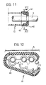
- the ends of the hollow profiled sections 10 at which the pipes T are connected to the respective units have elastomeric sealing caps 40 which are fitted in ends 42 of the profiled section 10 at 41 and can be split along shaped separation lines L so as to house the pipes T in the same way as the articulated rigid elements of the tubular profiled sections 10.
Landscapes
- Engineering & Computer Science (AREA)
- Mechanical Engineering (AREA)
- General Engineering & Computer Science (AREA)
- Life Sciences & Earth Sciences (AREA)
- Sustainable Development (AREA)
- Sustainable Energy (AREA)
- Chemical & Material Sciences (AREA)
- Combustion & Propulsion (AREA)
- Transportation (AREA)
- Cooling, Air Intake And Gas Exhaust, And Fuel Tank Arrangements In Propulsion Units (AREA)
- Motor Or Generator Frames (AREA)
- Quick-Acting Or Multi-Walled Pipe Joints (AREA)
Abstract
Description
- The present invention relates to a sub-assembly for supporting and housing pipes, electrical cables and the like, particularly for the fuel supply to a motor-vehicle engine.
- Current fuel-supply systems include shaped pipes of polyamide arranged on the floor of the vehicle. In order to define the exact path of the pipes (the delivery pipe and the pipe for recycling to the tank), they are preformed in several shaped sections before fitting and these are then assembled and fixed to the body in various ways.
- The fitting of the pipes is thus laborious and, in addition, the fuel pipes may sag between their supports and may have a poor resistance to the high temperatures which occur, for example, near the silencer or the exhaust pipe.
- French patent application No. FR-A-2179904 describes a system for connection between a fuel tank and an injection engine constituted by a substantially flat, flexible, profiled section comprising tubular portions placed side-by-side and joined together. Whilst it can be fitted quickly, this solution does not provide sufficient safety for mounting under the body since the pipes are not protected.
- The object of the present invention is to provide a sub-assembly associated with the fuel-supply system of a motor vehicle engine, which does not have the said disadvantages, which is simple and cheap to produce, and which can be installed quickly.
- According to the invention, this object is achieved by virtue of the fact that the sub-assemtly comprises rigid, tubular housing elements interconnected by bellows-like corrugated portions for enabling the sub-assembly to be shaped during its installation.
- The rigid tubular elements may be integral with the corrugated portions and, in this case, the sub-assembly is a single component which can be assembled with the other components of a main assembly such as, for example, the fuel-supply system in which the tank has to be connected to the supply pump.
- The tubular housing element preferably has a dovetail-shaped lateral rib for resilient snap-engagement in seats provided on the motor vehicle body outside the passenger compartment.
- By virtue of these characteristics, the preforming and assembly of the fuel pipes is thus avoided and, moreover, these may be made from materials which are more flexible and less expensive than polyamide. An important advantage results from the installation of the tubular element beneath the body since it avoids the problem of a smell of fuel within the passenger compartment due to its diffusion through the fuel pipes as a result of their porosity. The need for suitable support clips is also eliminated so that the assembly is an extremely quick and easy job for the fitter and can easily be automated.
- To advantage, the tubular element is constituted by a rigid sheath of plastics material which prevents any sagging of the fuel pipes or their abrasion due to gravel being thrown up beneath the body by the wheels. The tubular element may be corrugated throughout, thus ensuring greater resistance to impact by stones thrown up by the wheels. In a preferred embodiment, each element has a least two half-shells which are articulated longitudinally and are adapted to be joined together when closed. By virtue of this characteristic, the pipes enclosed in the tubular element can be replaced or checked without the need to remove it from the body of the motor vehicle.
- In this embodiment, the sub-assembly also includes saddle elements for supporting the pipes within the tubular element and adapted to be fixed to the motor-vehicle body through holes in one of the half-shells, the support elements also acting as supports for the tubular element.
- The pipes are thus supported by the support elements so that, when the lower half-shell is opened for the inspection or replacement of one of the pipes, the pipes remain in their predetermined positions.
- Further advantages and characteristics of the sub-assembly according to the invention will become clear from the detailed description which follows, purely by way of non-limiting example, with reference to the appended drawings, in which:
- Figure 1 is a schematic view of a sub-assembly according to the invention fitted to a motor vehicle.
- Figure 2 is a section taken on the line II-II of Figure 1 ,
- Figure 3 is a side view taken on the arrow III of Figure 1,
- Figure 4 is a cross-section of a tubular element of the sub-assembly according to another embodiment,
- Figure 5 is a view similar to Figure 4 and shows a tubular element adapted to be fitted in a recess in the body,
- Figure 6 is an exploded perspective view of a detail of Figure 5,
- Figure 7 is a view similar to Figure 4 and shows a different system for fixing the tubular element to the body,
- Figure 8 is a view similar to Figure 7,
- Figure 9 is a view of the tubular element taken on the arrow IX of Figures 7 and 8,
- Figure 10 is a detail of Figure 4, showing a variant of the fixing of the tubular element;
- Figure 11 is a cross-section of a tubular element according to the invention in correspondence with one of its ends, and
- Figure 12 is a section taken on the line XII-XII of Figure 11 with the tubular element in an open configuration.
- With reference to the drawings, a motor vehicle body is indicated S and has an internal combustion engine M, an exhaust pipe E and a fuel tank R.
- The fuel tank R and the supply to the engine M are connected by means of a fuel delivery pipe T, an excess-fuel return pipe and a breather pipe.
- These three pipes are housed in a single sheath 4 of rigid polymeric material which has a flattened, substantially oval shape and is provided with bellows-like
corrugated portions 4a in the regions where the sheath has to be bent in order to fit the shape of the body and the arrangement of the various members fixed to the body. - Throughout its length, or along predetermined portions, the sheath 4 has a
longitudinal rib 5 with a dovetail-shaped cross-section which can be resiliently snap-engaged with convergingtabs 6a ofengagement elements 6 welded electrically beneath the body S. - The sheath 4 may also be connected to the body S by conventional systems, for example, with the use of resilient clips.
- Moreover, near heat sources, such as the exhaust pipe E or the catalytic silencer, the affected section of the sheath 4 may be made from fireproof material suitably joined to the rest of the sheath so as to ensure its continuity.
- During the installation of the pipes T under the body S, the fitter snap-engages the
rib 5 of the sheath 4 resiliently inengagement elements 6 already provided on the body S and bends the sheath 4 manually in thecorrugated zones 4a. - Although the embodiment described above relates to fuel pipes, the sheath 4 may obviously also be used for supporting and housing electrical cables or air pipes so that the use of clips for holding cables and/or pipes together is superfluous.
- The second embodiment of the invention, shown in Figures 4-12, provides for the use of a hollow profiled
section 10 of polymeric material which is adapted to be fixed beneath a motor-vehicle body S and comprises a plurality of substantially rigidlongitudinal portions section 10 is closed by adeformable coupling 12 which can be opened by the manual operation of atongue 14 and is adapted to be resiliently snap-engaged upon closure. Therigid part 10a of the the profiledsection 10 which faces the body S has holes A for the passage of flanged fixing pins P welded to the body S. - Saddle-
like supports 16 of polymeric material are force-fitted on the pins P with the profiledsection 10 in the open configuration, and comprise ashank portion 16a, a plurality ofsupport saddles 16b for pipes T, and a flangedportion 16c which faces an internal wall of the profiledsection 10 and is coaxial with anannular seat 18 formed in correspondence with acentral hole 19 in theshank portion 16a. A correspondingannular portion 20 of aspacer element 22, interposed between the body S and thepart 10a of theprofiled section 10 when the sheath is in the installed configuration, is resiliently snap-engaged in theannular seat 18. Thewall 10a is thus clamped between thespacer element 22 and the flangedportion 16c of thesaddle support 16. As well as supporting the pipes T, thesupports 16 are also used for supporting the profiledsection 10 itself. - The variant shown in Figure 5 has a profiled
section 10 of a slightly different shape and asaddle support 16 which is adapted for a larger number of pipes or cables T. In this embodiment, the shape of the profiledsection 10 is designed so that it fits a recess in the body of the motor vehicle. - Figure 7 shows a different type of attachment for fixing the
saddle support 16 to the body S. In this embodiment, the flangedportion 16c has an integral auxiliary flangedportion 24 and an integral deformablecylindrical end 26 which is adapted to be inserted in a hole H in the body S. The flangedportion 16c and the auxiliaryintegral flange 24 form parts of a bayonet coupling adapted to be inserted in a shaped aperture A₁ in the profiledsection 10, as shown in Figure 9, and then rotated through 90o. By virtue of this rotation, thewall 10a of the profiledsection 10 is interposed between the flangedportion 16c and the auxiliaryintegral flange 24, thus fixing thesaddle support 16 to the profiledsection 10. In order to prevent thecylindrical ends 26 from coming out of the holes H in the body S,metal pins 30 are inserted incentral holes 19′ in the saddle supports 16 and, by suitably expanding theends 26, prevent them from accidentally coming out. After the profiledsection 10 has been fixed to the body S, the pipes T can be inserted therein and the profiledsection 10 then closed. Clearly, the variant shown in Figure 7 is particularly suitable for manual fitting, whilst the variant of Figures 4-5 is particularly suitable for automatic fitting. - The variant of Figure 8 shows a profiled section which is similar to that of Figure 7 but is suitable for the manual fitting of the closed profiled section complete with pipes T to the body. In this variant, the
wall 10c of the profiledsection 10 opposite thewall 10a for fixing to the body hasholes 32 for the insertion ofplug elements 34 having resilient snap-engagement flanges 34a for cooperating withcorresponding engagement portions 36 integral with the saddle supports 16. The assembly of the profiledsection 10, the saddle support 16 and the pipes T can thus be connected directly to the body S by the insertion of thecylindrical ends 26 in the appropriate holes H and the subsequent insertion of thelocking pins 30 through theholes 32. As well as ensuring a perfect seal within the hollow profiledsection 10, theplug elements 34 also help thelongitudinal coupling 12 to keep the profiled section closed. - For this purpose, the hollow profiled section shown in Figure 1 may be modified as shown in Figure 10, in which the
saddle support 16 includes afurther portion 16d opposite the flangedportion 16c and engageable by theplug element 34. The complete closure of the openable profiledsection 10 is thus ensured should theengagement system 12 not be wholly reliable. - The ends of the hollow profiled
sections 10 at which the pipes T are connected to the respective units (tank, carburettor, etc.) haveelastomeric sealing caps 40 which are fitted inends 42 of the profiledsection 10 at 41 and can be split along shaped separation lines L so as to house the pipes T in the same way as the articulated rigid elements of the tubular profiledsections 10.
Claims (12)
Priority Applications (1)
| Application Number | Priority Date | Filing Date | Title |
|---|---|---|---|
| AT90830358T ATE102553T1 (en) | 1989-08-04 | 1990-07-31 | PREASSEMBLED UNIT FOR CAR ENGINE POWER SUPPLY. |
Applications Claiming Priority (4)
| Application Number | Priority Date | Filing Date | Title |
|---|---|---|---|
| IT8967682A IT1232430B (en) | 1989-08-04 | 1989-08-04 | Conduit system for housing vehicle fuel pipes |
| IT6768289 | 1989-08-04 | ||
| IT5305590U IT220396Z2 (en) | 1990-05-23 | 1990-05-23 | SUBSYSTEM FOR FUEL SUPPLY TO A MOTOR VEHICLE ENGINE |
| IT5305590U | 1990-05-23 |
Publications (2)
| Publication Number | Publication Date |
|---|---|
| EP0412067A1 true EP0412067A1 (en) | 1991-02-06 |
| EP0412067B1 EP0412067B1 (en) | 1994-03-09 |
Family
ID=26329524
Family Applications (1)
| Application Number | Title | Priority Date | Filing Date |
|---|---|---|---|
| EP90830358A Expired - Lifetime EP0412067B1 (en) | 1989-08-04 | 1990-07-31 | A subassembly for the fuel supply to a motor vehicle engine |
Country Status (3)
| Country | Link |
|---|---|
| EP (1) | EP0412067B1 (en) |
| DE (1) | DE69007202T2 (en) |
| ES (1) | ES2043589T3 (en) |
Cited By (10)
| Publication number | Priority date | Publication date | Assignee | Title |
|---|---|---|---|---|
| GB2276695A (en) * | 1993-03-29 | 1994-10-05 | Guido Juergen Dipl Ing | Pipe clip member |
| FR2713838A1 (en) * | 1993-12-09 | 1995-06-16 | United Carr Gmbh Trw | Plastic conduit for receiving electrical cables in motor vehicle |
| EP0661187A1 (en) * | 1993-12-28 | 1995-07-05 | DAYCO EUROPE S.p.A. | Guiding member for pipes |
| EP0668179A3 (en) * | 1994-02-17 | 1996-09-04 | Technoflow Tube Systems Gmbh | Preassembled fluid piping, adapted to the mounting into a motor vehicle on an automatised assembly line. |
| WO2003058106A1 (en) * | 2001-12-18 | 2003-07-17 | Volvo Lastvagnar Ab | Support device to be used for attaching pipes and cables to a vehicle, comprising a console designed with a convex envelope surface |
| WO2006124745A3 (en) * | 2005-05-17 | 2007-01-04 | Honeywell Int Inc | Fuel distributor and mounting system therefor and method of mounting a fuel distributor |
| ITMO20110333A1 (en) * | 2011-12-23 | 2013-06-24 | C M C S R L Societa Unipersonal E | METHOD AND EQUIPMENT TO MAINTAIN FLEXIBLE PIPES OR FLEXIBLE DUCTS |
| EP3067274A1 (en) * | 2015-03-10 | 2016-09-14 | The Boeing Company | Duct assembly and method of assembling thereof |
| FR3081962A1 (en) * | 2018-05-29 | 2019-12-06 | Psa Automobiles Sa | SPACER FOR MOUNTING A PIPE OF A MOTOR VEHICLE |
| WO2023152945A1 (en) * | 2022-02-14 | 2023-08-17 | 三菱自動車工業株式会社 | Protective structure for fuel pipe |
Families Citing this family (1)
| Publication number | Priority date | Publication date | Assignee | Title |
|---|---|---|---|---|
| DE102018109476B4 (en) | 2018-04-20 | 2024-08-29 | Dr. Ing. H.C. F. Porsche Aktiengesellschaft | Cable holder |
Citations (5)
| Publication number | Priority date | Publication date | Assignee | Title |
|---|---|---|---|---|
| US3151905A (en) * | 1960-07-27 | 1964-10-06 | Gen Motors Corp | Conduit assembly |
| DE1938128A1 (en) * | 1965-10-19 | 1971-01-28 | Liverpa Gmbh | Profile rail for motor vehicles |
| FR2194904A1 (en) * | 1972-08-02 | 1974-03-01 | Herburg Armaturen | |
| FR2533996A3 (en) * | 1982-10-04 | 1984-04-06 | Caoutchouc Manuf Plastique | Flexible junction pipe for vehicle fluid circuits. |
| EP0338609A1 (en) * | 1988-04-19 | 1989-10-25 | Rudolphus Adrianus Jeanne Marie Van Boxel | Gas flow line with conductor for switch-over on vehicles |
Family Cites Families (3)
| Publication number | Priority date | Publication date | Assignee | Title |
|---|---|---|---|---|
| DE2217252A1 (en) * | 1972-04-11 | 1973-10-31 | Daimler Benz Ag | CONNECTION BETWEEN A FUEL INJECTION ENGINE AND A FUEL TANK |
| US4669508A (en) * | 1985-10-31 | 1987-06-02 | The Gates Rubber Company | Formable and curve shape retentive hose |
| DE3631183A1 (en) * | 1986-09-12 | 1988-03-24 | Gebr Hennig Gmbh | POWER SUPPLY HOSE |
-
1990
- 1990-07-31 EP EP90830358A patent/EP0412067B1/en not_active Expired - Lifetime
- 1990-07-31 ES ES90830358T patent/ES2043589T3/en not_active Expired - Lifetime
- 1990-07-31 DE DE1990607202 patent/DE69007202T2/en not_active Expired - Fee Related
Patent Citations (5)
| Publication number | Priority date | Publication date | Assignee | Title |
|---|---|---|---|---|
| US3151905A (en) * | 1960-07-27 | 1964-10-06 | Gen Motors Corp | Conduit assembly |
| DE1938128A1 (en) * | 1965-10-19 | 1971-01-28 | Liverpa Gmbh | Profile rail for motor vehicles |
| FR2194904A1 (en) * | 1972-08-02 | 1974-03-01 | Herburg Armaturen | |
| FR2533996A3 (en) * | 1982-10-04 | 1984-04-06 | Caoutchouc Manuf Plastique | Flexible junction pipe for vehicle fluid circuits. |
| EP0338609A1 (en) * | 1988-04-19 | 1989-10-25 | Rudolphus Adrianus Jeanne Marie Van Boxel | Gas flow line with conductor for switch-over on vehicles |
Cited By (14)
| Publication number | Priority date | Publication date | Assignee | Title |
|---|---|---|---|---|
| GB2276695A (en) * | 1993-03-29 | 1994-10-05 | Guido Juergen Dipl Ing | Pipe clip member |
| GB2276695B (en) * | 1993-03-29 | 1997-07-16 | Guido Juergen Dipl Ing | Injection line assembly |
| FR2713838A1 (en) * | 1993-12-09 | 1995-06-16 | United Carr Gmbh Trw | Plastic conduit for receiving electrical cables in motor vehicle |
| EP0661187A1 (en) * | 1993-12-28 | 1995-07-05 | DAYCO EUROPE S.p.A. | Guiding member for pipes |
| EP0668179A3 (en) * | 1994-02-17 | 1996-09-04 | Technoflow Tube Systems Gmbh | Preassembled fluid piping, adapted to the mounting into a motor vehicle on an automatised assembly line. |
| WO2003058106A1 (en) * | 2001-12-18 | 2003-07-17 | Volvo Lastvagnar Ab | Support device to be used for attaching pipes and cables to a vehicle, comprising a console designed with a convex envelope surface |
| WO2006124745A3 (en) * | 2005-05-17 | 2007-01-04 | Honeywell Int Inc | Fuel distributor and mounting system therefor and method of mounting a fuel distributor |
| US7516736B2 (en) | 2005-05-17 | 2009-04-14 | Honeywell International Inc. | Fuel distributor and mounting system therefor and method of mounting a fuel distributor |
| ITMO20110333A1 (en) * | 2011-12-23 | 2013-06-24 | C M C S R L Societa Unipersonal E | METHOD AND EQUIPMENT TO MAINTAIN FLEXIBLE PIPES OR FLEXIBLE DUCTS |
| EP3067274A1 (en) * | 2015-03-10 | 2016-09-14 | The Boeing Company | Duct assembly and method of assembling thereof |
| EP3388339A1 (en) * | 2015-03-10 | 2018-10-17 | The Boeing Company | Duct assembly and method of assembling thereof |
| FR3081962A1 (en) * | 2018-05-29 | 2019-12-06 | Psa Automobiles Sa | SPACER FOR MOUNTING A PIPE OF A MOTOR VEHICLE |
| WO2023152945A1 (en) * | 2022-02-14 | 2023-08-17 | 三菱自動車工業株式会社 | Protective structure for fuel pipe |
| JP7597252B2 (en) | 2022-02-14 | 2024-12-10 | 三菱自動車工業株式会社 | Fuel piping protection structure |
Also Published As
| Publication number | Publication date |
|---|---|
| ES2043589T1 (en) | 1994-01-01 |
| DE69007202D1 (en) | 1994-04-14 |
| ES2043589T3 (en) | 1994-05-01 |
| DE69007202T2 (en) | 1994-06-16 |
| EP0412067B1 (en) | 1994-03-09 |
Similar Documents
| Publication | Publication Date | Title |
|---|---|---|
| EP0412067B1 (en) | A subassembly for the fuel supply to a motor vehicle engine | |
| US5794979A (en) | Method and structure for mounting a fuel tank | |
| CN109510123B (en) | Wire harness | |
| US6855884B2 (en) | Protection member for a mesh cable tray, and a tray including said member | |
| US6305408B1 (en) | Fuel tank and fuel feeding apparatus used therefor | |
| US20050028963A1 (en) | Vibration and heat insulating board | |
| JPH04262940A (en) | Fastening for mounting gas bag to receiving housing | |
| US7044537B2 (en) | Air duct assembly | |
| DE19515569C2 (en) | Device for the electrical connection of electrical components arranged in the intake system of an internal combustion engine | |
| GB2327478A (en) | Device for connecting tubular components | |
| US6015952A (en) | Grommet and method for arranging the same and use thereof | |
| KR100280065B1 (en) | Fuel Conduits for Automotive Fuel Supply | |
| PL184312B1 (en) | Fuel tank filler passage assembly, in particular for automotive vehicles | |
| US6036145A (en) | Integrated system for protecting and fastening pipes to a supporting structure, particularly of a vehicle | |
| US4888453A (en) | Panel mounted breakout fitting | |
| US5960833A (en) | Fuel filler neck assembly | |
| US6619343B2 (en) | Seal for fuel filler tubes | |
| CN111456834B (en) | Device for an exhaust system of a vehicle | |
| EP0938628B1 (en) | Suction module for an internal combustion engine | |
| GB2221573A (en) | Noise isolated relay | |
| DE19930900A1 (en) | poetry | |
| DE102024116435A1 (en) | Air-exhaust duct system for a heater in a caravanning vehicle, elbow fitting for such an air-exhaust duct system and heater for a caravanning vehicle | |
| US12115923B2 (en) | Earth structure for filler pipe | |
| RU2203190C2 (en) | Filler pipe unit for fuel tank of motorized vehicle | |
| JP2001180554A (en) | Flexible long object clamp in vehicle |
Legal Events
| Date | Code | Title | Description |
|---|---|---|---|
| PUAI | Public reference made under article 153(3) epc to a published international application that has entered the european phase |
Free format text: ORIGINAL CODE: 0009012 |
|
| AK | Designated contracting states |
Kind code of ref document: A1 Designated state(s): AT BE CH DE DK ES FR GB GR IT LI LU NL SE |
|
| 17P | Request for examination filed |
Effective date: 19910725 |
|
| 17Q | First examination report despatched |
Effective date: 19920601 |
|
| GRAA | (expected) grant |
Free format text: ORIGINAL CODE: 0009210 |
|
| AK | Designated contracting states |
Kind code of ref document: B1 Designated state(s): AT BE CH DE DK ES FR GB GR IT LI LU NL SE |
|
| PG25 | Lapsed in a contracting state [announced via postgrant information from national office to epo] |
Ref country code: LI Effective date: 19940309 Ref country code: AT Effective date: 19940309 Ref country code: CH Effective date: 19940309 Ref country code: BE Effective date: 19940309 Ref country code: DK Effective date: 19940309 Ref country code: SE Free format text: THE PATENT HAS BEEN ANNULLED BY A DECISION OF A NATIONAL AUTHORITY Effective date: 19940309 Ref country code: GR Free format text: LAPSE BECAUSE OF FAILURE TO SUBMIT A TRANSLATION OF THE DESCRIPTION OR TO PAY THE FEE WITHIN THE PRESCRIBED TIME-LIMIT Effective date: 19940309 Ref country code: NL Effective date: 19940309 |
|
| REF | Corresponds to: |
Ref document number: 102553 Country of ref document: AT Date of ref document: 19940315 Kind code of ref document: T |
|
| ITF | It: translation for a ep patent filed | ||
| REF | Corresponds to: |
Ref document number: 69007202 Country of ref document: DE Date of ref document: 19940414 |
|
| REG | Reference to a national code |
Ref country code: ES Ref legal event code: FG2A Ref document number: 2043589 Country of ref document: ES Kind code of ref document: T3 |
|
| ET | Fr: translation filed | ||
| REG | Reference to a national code |
Ref country code: CH Ref legal event code: PL |
|
| PG25 | Lapsed in a contracting state [announced via postgrant information from national office to epo] |
Ref country code: LU Free format text: LAPSE BECAUSE OF NON-PAYMENT OF DUE FEES Effective date: 19940731 |
|
| NLV1 | Nl: lapsed or annulled due to failure to fulfill the requirements of art. 29p and 29m of the patents act | ||
| PLBE | No opposition filed within time limit |
Free format text: ORIGINAL CODE: 0009261 |
|
| STAA | Information on the status of an ep patent application or granted ep patent |
Free format text: STATUS: NO OPPOSITION FILED WITHIN TIME LIMIT |
|
| 26N | No opposition filed | ||
| REG | Reference to a national code |
Ref country code: GB Ref legal event code: IF02 |
|
| PG25 | Lapsed in a contracting state [announced via postgrant information from national office to epo] |
Ref country code: IT Free format text: LAPSE BECAUSE OF NON-PAYMENT OF DUE FEES;WARNING: LAPSES OF ITALIAN PATENTS WITH EFFECTIVE DATE BEFORE 2007 MAY HAVE OCCURRED AT ANY TIME BEFORE 2007. THE CORRECT EFFECTIVE DATE MAY BE DIFFERENT FROM THE ONE RECORDED. Effective date: 20050731 |
|
| PGFP | Annual fee paid to national office [announced via postgrant information from national office to epo] |
Ref country code: ES Payment date: 20070615 Year of fee payment: 18 |
|
| PGFP | Annual fee paid to national office [announced via postgrant information from national office to epo] |
Ref country code: DE Payment date: 20070621 Year of fee payment: 18 |
|
| PGFP | Annual fee paid to national office [announced via postgrant information from national office to epo] |
Ref country code: GB Payment date: 20070622 Year of fee payment: 18 |
|
| PGFP | Annual fee paid to national office [announced via postgrant information from national office to epo] |
Ref country code: FR Payment date: 20070731 Year of fee payment: 18 |
|
| GBPC | Gb: european patent ceased through non-payment of renewal fee |
Effective date: 20080731 |
|
| PG25 | Lapsed in a contracting state [announced via postgrant information from national office to epo] |
Ref country code: DE Free format text: LAPSE BECAUSE OF NON-PAYMENT OF DUE FEES Effective date: 20090203 |
|
| REG | Reference to a national code |
Ref country code: FR Ref legal event code: ST Effective date: 20090331 |
|
| PG25 | Lapsed in a contracting state [announced via postgrant information from national office to epo] |
Ref country code: GB Free format text: LAPSE BECAUSE OF NON-PAYMENT OF DUE FEES Effective date: 20080731 |
|
| PG25 | Lapsed in a contracting state [announced via postgrant information from national office to epo] |
Ref country code: FR Free format text: LAPSE BECAUSE OF NON-PAYMENT OF DUE FEES Effective date: 20080731 |
|
| REG | Reference to a national code |
Ref country code: ES Ref legal event code: FD2A Effective date: 20080801 |
|
| PG25 | Lapsed in a contracting state [announced via postgrant information from national office to epo] |
Ref country code: ES Free format text: LAPSE BECAUSE OF NON-PAYMENT OF DUE FEES Effective date: 20080801 |