EP0411836A2 - Image processing apparatus - Google Patents
Image processing apparatus Download PDFInfo
- Publication number
- EP0411836A2 EP0411836A2 EP90308250A EP90308250A EP0411836A2 EP 0411836 A2 EP0411836 A2 EP 0411836A2 EP 90308250 A EP90308250 A EP 90308250A EP 90308250 A EP90308250 A EP 90308250A EP 0411836 A2 EP0411836 A2 EP 0411836A2
- Authority
- EP
- European Patent Office
- Prior art keywords
- information
- processing apparatus
- image
- bus
- image information
- Prior art date
- Legal status (The legal status is an assumption and is not a legal conclusion. Google has not performed a legal analysis and makes no representation as to the accuracy of the status listed.)
- Withdrawn
Links
Images


Classifications
-
- G—PHYSICS
- G06—COMPUTING; CALCULATING OR COUNTING
- G06F—ELECTRIC DIGITAL DATA PROCESSING
- G06F16/00—Information retrieval; Database structures therefor; File system structures therefor
- G06F16/50—Information retrieval; Database structures therefor; File system structures therefor of still image data
- G06F16/53—Querying
- G06F16/532—Query formulation, e.g. graphical querying
-
- G—PHYSICS
- G06—COMPUTING; CALCULATING OR COUNTING
- G06T—IMAGE DATA PROCESSING OR GENERATION, IN GENERAL
- G06T1/00—General purpose image data processing
Landscapes
- Engineering & Computer Science (AREA)
- Physics & Mathematics (AREA)
- Theoretical Computer Science (AREA)
- General Physics & Mathematics (AREA)
- Mathematical Physics (AREA)
- Data Mining & Analysis (AREA)
- Databases & Information Systems (AREA)
- General Engineering & Computer Science (AREA)
- Processing Or Creating Images (AREA)
- Computer And Data Communications (AREA)
- Storing Facsimile Image Data (AREA)
- Bus Control (AREA)
Abstract
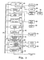
An image processing apparatus for processing a communication of image information between an optical disc (20) and external information handling device. The apparatus includes an interface controller for interfacing the external information handling means to the apparatus, an optical disc driver for driving the optical disc (20) to store the image information together with associated information for retrieving image information and to reproduce a desired image information from the optical disc (20) by using the associated retrieving information, a main CPU (34) for commanding the communication of the image information between the optical disc (20) and the external information handling device and for supplying associated information for communicating the image information, a common memory (70) for storing the associated communicating information from the main CPU (34) and a sub CPU (62) responsive to the main CPU (34) for controlling the interface controller (82, 83, 84) and the optical disc driver (22) to communicate the image information under the control of the associated communicating information stored in the common memory (70).
Description
- The present invention relates generally to an image processing apparatus, and more particularly, to an image processing apparatus such as an image filing apparatus which is able to communicate with an external device through a communication line. Recently, an image processing apparatus has been put in practical use which reads image data, such as documents created in large quantities, through a two-dimensional scanner, stores this read image data on an optical disc, retrieves and reads the stored image data and outputs them in a visible state on an output device, for instance, a CRT display device. In such an image processing apparatus, a microcomputer (hereinafter referred to as CPU) is used as a processor to process or retrieve image data read out of an optical disc device, and this CPU is capable of accessing memories and various processing modules of the apparatus. A communication interface is generally provided as one of such processing modules, for the purpose of transmitting/receiving image information between the image processing apparatus and external devices via communication circuits. This communication interface operates under the control of the CPU. However, one problem with such image processing apparatus is that the CPU directly controls the communication interface, The CPU may become heavily loaded and the system will not meet the prescribed performance. This may happen many kinds of external devices are connected to the communication interface, each requiring different rapid processing capabilities. This defect was most apparent when external devices having large loads, as a LAN (Local Area Network) controller or the like, were connected to the CPU. A DMA (Direct Memory Access) channel is generally provided as another of the processing modules. Under the control of this DMA channel, the transmitting/receiving of image information is performed between a memory and an external device through the system bus. Therefore, a request for use of the system bus may be generated simultaneously from both the CPU and the DMA channel. When this happens, it becomes necessary to mediate and control which of the CPU and DMA channel have the right to use the system bus. Where there are multiple bus masters, a round robin system of bus mediations has been known. This round robin system is a method to control use of the bus by giving the lowest priority to the bus master which used the bus most recently to prevent the use of the bus from being concentrated in specific bus masters. This round robin system however, had a defect in that as the number of bus masters increased, the bus control circuit became more complicated and the number of hardware elements containing image processing apparatus increased. As described above, in the one of the processing modules the CPU directly controls the communication interface. Thus, the CPU may become heavily loaded and the entire system may not display the prescribed performance because many kinds devices are connected to the communication interface. This requires the interface to provide different type of processing rapidly to each of these external devices. In the other type of processing module, as the number of bus masters increases, the mediation control circuit becomes more complicated and the number of hardware elements increases if the round robin system is used. The present invention therefore seeks to provide an image processing apparatus which is able to overcome the disadvantages of the conventional apparatus. The present invention also seeks to provide an image processing apparatus which is able to reduce the load on the CPU and to perform as designed. The present invention further seeks to provide an image processing apparatus in which the mediation control circuit is not complicated even if the number of bus masters increases, so that the increase in the amount of hardware elements can be constrained. Accordingly, the present invention provides an image processing apparatus for controlling the communication of image information between a recording medium and external information handling means, which comprises at least one interfacing means for interfacing the external information handling means to the apparatus and means for driving the recording medium to store the image information together with associated retrieval information and to reproduce a desired image information from the recording medium by using the associated retrieval information, characterised in that the apparatus further comprises:
first processing means for commanding the communication of the image information between the recording medium and the external information handling means and for supplying associated information for communicating the image information;
storage means for storing the associated communication information from the first processing means; and
second processing means responsive to the first processing means for controlling the interfacing means and the driving means to communicate the image information under the control of the associated communicating information stored in the storage means. An image processing apparatus for processing a communication of image information between an optical disc and external information handling device according to another aspect of the present invention includes first and second interface controllers for interfacing the external information handling means to the apparatus, an optical disc driver for driving the recording medium to store the image information together with associated information for retrieving image information and to reproduce a desired image information from the recording medium by using the associated retrieving information, a main CPU for commanding the communication of the image information between the recording medium and the external information handling means and for supplying associated information for communicating the image information, a first common memory for storing the associated communicating information from the main CPU, a first sub CPU responsive to the main CPU for controlling the first interface controller and the optical disc driver to communicate the image information under the control of the associated communicating information stored in the first common memory when the communication of the image information through the first interface controller is commanded by the main CPU, the first sub CPU also commanding the communication of the image information between the recording medium and the external information handling means and for supplying associated information for communicating the image information when the communication of the image information through the second interface controller is commanded by the main CPU, a second common memory for storing the associated communicating information from the first common memory and a second sub CPU responsive to the first sub CPU for controlling the second interface controller and the optical disc driver to communicate the image information under the control of the associated communicating information stored in the second common memory. For a better understanding of the present invention and many of the attendant advantages thereof reference will now be made by way of example to the accompanying drawings, wherein: - FIGURE 1 is a block diagram briefly showing the general construction of the image processing apparatus;
- FIGURE 2 is a block diagram briefly showing the construction of the communication interface of the first embodiment of the image processing apparatus according to the present invention;
- FIGURE 3 is a diagram showing the control system for explaining the operation of the first embodiment of the image processing apparatus according to the present invention;
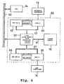
- FIGURE 4 is a block diagram briefly showing the construction of the communication interface of the second embodiment of the image processing apparatus according to the present invention;
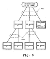
- FIGURE 5 is a diagram for explaining the concept of the bus mediation control operation for the second embodiment of the image processing apparatus according to the present invention; and
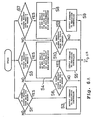
- FIGURES 6A and 6B are flowcharts for explaining the operation of the second embodiment of the image processing apparatus according to the present invention when combined together.
Claims (14)
1. An image processing apparatus for controlling the communication of image information between a recording medium (20) and external information handling means, which comprises at least one interfacing means (82, 83, 84) for interfacing the external information handling means to the apparatus and means (22) for driving the recording medium (20) to store the image information together with associated retrieval information and to reproduce a desired image information from the recording medium (20) by using the associated retrieval information, characterised in that the apparatus further comprises:
first processing means (34) for commanding the communication of the image information between the recording medium (20) and the external information handling means and for supplying associated information for communicating the image information;
storage means (70) for storing the associated communication information from the first processing means (34); and
second processing means (62) responsive to the first processing means (34) for controlling the interfacing means (82, 83, 84) and the driving means (22) to communicate the image information under the control of the associated communicating information stored in the storage means (70).
2. Image processing apparatus according to claim 1, further characterised by second interfacing means 85 for interfacing external information handling means to the apparatus, and the storage means comprising first and second storage means (70a, 70b);
the second processing means (62) also being arranged to control the communication of image information between the recording medium (20) and the external information handling means and to supply associated information for communicating the image information when the communication of the image information through the second interfacing means (85) is commanded by the first processing means (34);
the associated communicating information from the second processing means (62) being stored in first storage means 70a; and
third processing means (66) responsive to the second processing means (62) for controlling the second interfacing means (85) and the driving means (22) to communicate the image information under the control of the associated communicating information stored in the second storage means (70b).
3. An image processing apparatus according to claim 1 or claim 2 recording medium is an optical disc.
4. An image processing apparatus according to any preceding claim, wherein said interfacing means includes an RS-232C interface controller (82).
5. An image processing apparatus according to any preceding claim, wherein said interfacing means includes a GP-IB interface controller (83).
6. An image processing apparatus according to any preceding claim, wherein said interfacing means includes an SCSI interface controller (84).
7. An image processing apparatus according to a.p.c. wherein said second processing means comprises a sub CPU (62).
8. An image processing apparatus according to claim 7, wherein said second processing means further comprises a direct memory access controller (64).
9. An image processing apparatus according to claim 7 or claim 8 wherein said second processing means further comprises an interrupt controller (80).
10. An image processing apparatus according to any of claims 7 to 9, wherein said second processing means further comprises a read only memory (ROM 81).
11. An image processing apparatus according to claim 1, wherein said second interfacing means comprises a LAN interface controller (85).
12. An image processing apparatus according to claim 2, wherein said third processing means comprises a sub CPU (66).
13. An image processing apparatus according to claim 12, wherein said third processing means further comprises a direct memory access controller (85).
14. An image processing apparatus according to claim 12 or claim 13 wherein said third processing means further comprises a read only memory (ROM 86).
Applications Claiming Priority (4)
| Application Number | Priority Date | Filing Date | Title |
|---|---|---|---|
| JP1198317A JPH0362250A (en) | 1989-07-31 | 1989-07-31 | Picture information processor |
| JP198341/89 | 1989-07-31 | ||
| JP1198341A JPH0362264A (en) | 1989-07-31 | 1989-07-31 | Picture information processor |
| JP198317/89 | 1989-07-31 |
Publications (2)
| Publication Number | Publication Date |
|---|---|
| EP0411836A2 true EP0411836A2 (en) | 1991-02-06 |
| EP0411836A3 EP0411836A3 (en) | 1993-02-03 |
Family
ID=26510912
Family Applications (1)
| Application Number | Title | Priority Date | Filing Date |
|---|---|---|---|
| EP19900308250 Withdrawn EP0411836A3 (en) | 1989-07-31 | 1990-07-27 | Image processing apparatus |
Country Status (2)
| Country | Link |
|---|---|
| EP (1) | EP0411836A3 (en) |
| KR (1) | KR930004441B1 (en) |
Families Citing this family (1)
| Publication number | Priority date | Publication date | Assignee | Title |
|---|---|---|---|---|
| KR100650609B1 (en) * | 2000-06-17 | 2006-11-28 | 삼성중공업 주식회사 | Butt antomatic welding method of thick plate with narrow gap for welding |
Citations (4)
| Publication number | Priority date | Publication date | Assignee | Title |
|---|---|---|---|---|
| US4603400A (en) * | 1982-09-30 | 1986-07-29 | Pitney Bowes Inc. | Mailing system interface interprocessor communications channel |
| EP0245504A1 (en) * | 1985-08-08 | 1987-11-19 | Fanuc Ltd. | Image processor |
| US4782397A (en) * | 1986-05-30 | 1988-11-01 | Kabushiki Kaisha Toshiba | Image data processing apparatus with editing function |
| DE3925149A1 (en) * | 1988-07-29 | 1990-02-01 | Toshiba Kk | Picture processing system for output on CRT-screen or printer - has compander or codec and enlarger-reducer connected by internal bus coupled via gate to picture bus where linear density conversion occurs |
-
1990
- 1990-07-27 EP EP19900308250 patent/EP0411836A3/en not_active Withdrawn
- 1990-07-31 KR KR1019900011844A patent/KR930004441B1/en not_active IP Right Cessation
Patent Citations (4)
| Publication number | Priority date | Publication date | Assignee | Title |
|---|---|---|---|---|
| US4603400A (en) * | 1982-09-30 | 1986-07-29 | Pitney Bowes Inc. | Mailing system interface interprocessor communications channel |
| EP0245504A1 (en) * | 1985-08-08 | 1987-11-19 | Fanuc Ltd. | Image processor |
| US4782397A (en) * | 1986-05-30 | 1988-11-01 | Kabushiki Kaisha Toshiba | Image data processing apparatus with editing function |
| DE3925149A1 (en) * | 1988-07-29 | 1990-02-01 | Toshiba Kk | Picture processing system for output on CRT-screen or printer - has compander or codec and enlarger-reducer connected by internal bus coupled via gate to picture bus where linear density conversion occurs |
Non-Patent Citations (1)
| Title |
|---|
| COMPUTER, vol. 21, no. 9, September 1988, NEW YORK, US; pages 13 - 30 T. DIEDE ET AL 'The Titan Graphics Supercomputer Architecture' * |
Also Published As
| Publication number | Publication date |
|---|---|
| KR930004441B1 (en) | 1993-05-27 |
| EP0411836A3 (en) | 1993-02-03 |
| KR910003525A (en) | 1991-02-27 |
Similar Documents
| Publication | Publication Date | Title |
|---|---|---|
| US4110823A (en) | Soft display word processing system with multiple autonomous processors | |
| US7962712B2 (en) | Method for controlling storage device controller, storage device controller, and program | |
| US6446140B1 (en) | Data input/output device, data input/output method and storage medium | |
| US5195174A (en) | Image data processing apparatus capable of composing one image from a plurality of images | |
| US5404479A (en) | Electronic filing apparatus for filing and retrieving document data in a disk storage medium | |
| US5179683A (en) | Retrieval apparatus including a plurality of retrieval units | |
| EP0411836A2 (en) | Image processing apparatus | |
| JPH10283204A (en) | Multi-task processing method, multi-task processor and recording medium recording task | |
| JPH11184801A (en) | Interface device and data processing system | |
| JPH0362250A (en) | Picture information processor | |
| JPS58169390A (en) | Writing for buffer memory | |
| JP2700552B2 (en) | Image filing system | |
| JPH05342120A (en) | Network type document control system | |
| JPH0362264A (en) | Picture information processor | |
| JPH064494A (en) | Plural file merging system | |
| JPH02170255A (en) | Bus controller and picture information processor | |
| JPS5840212B2 (en) | Scan processing method | |
| EP0488035A1 (en) | Information processing apparatus with alterable network address | |
| JP2721440B2 (en) | Data copy method for auxiliary storage device | |
| JPH09186836A (en) | Digital copying machine | |
| JPH04275675A (en) | Data base processing system | |
| JPH05303474A (en) | Control device for page printer | |
| JP2776125B2 (en) | Image playback device | |
| JPS6139285A (en) | Information retrieving device | |
| JPS6393031A (en) | Transfer system for display picture data |
Legal Events
| Date | Code | Title | Description |
|---|---|---|---|
| PUAI | Public reference made under article 153(3) epc to a published international application that has entered the european phase |
Free format text: ORIGINAL CODE: 0009012 |
|
| 17P | Request for examination filed |
Effective date: 19900821 |
|
| AK | Designated contracting states |
Kind code of ref document: A2 Designated state(s): DE FR GB |
|
| PUAL | Search report despatched |
Free format text: ORIGINAL CODE: 0009013 |
|
| AK | Designated contracting states |
Kind code of ref document: A3 Designated state(s): DE FR GB |
|
| STAA | Information on the status of an ep patent application or granted ep patent |
Free format text: STATUS: THE APPLICATION HAS BEEN WITHDRAWN |
|
| 18W | Application withdrawn |
Withdrawal date: 19940808 |