EP0411358B1 - Bodeneffekt-Fluggerät - Google Patents
Bodeneffekt-Fluggerät Download PDFInfo
- Publication number
- EP0411358B1 EP0411358B1 EP90113277A EP90113277A EP0411358B1 EP 0411358 B1 EP0411358 B1 EP 0411358B1 EP 90113277 A EP90113277 A EP 90113277A EP 90113277 A EP90113277 A EP 90113277A EP 0411358 B1 EP0411358 B1 EP 0411358B1
- Authority
- EP
- European Patent Office
- Prior art keywords
- ground
- main body
- float
- effect wing
- craft
- Prior art date
- Legal status (The legal status is an assumption and is not a legal conclusion. Google has not performed a legal analysis and makes no representation as to the accuracy of the status listed.)
- Expired - Lifetime
Links
Images


Classifications
-
- B—PERFORMING OPERATIONS; TRANSPORTING
- B60—VEHICLES IN GENERAL
- B60V—AIR-CUSHION VEHICLES
- B60V1/00—Air-cushion
- B60V1/22—Air-cushion provided with hydrofoils
-
- B—PERFORMING OPERATIONS; TRANSPORTING
- B60—VEHICLES IN GENERAL
- B60V—AIR-CUSHION VEHICLES
- B60V1/00—Air-cushion
- B60V1/08—Air-cushion wherein the cushion is created during forward movement of the vehicle by ram effect
Definitions
- the present invention relates to a ground-surface-effect wing craft having an intermediate capability between a ship and an aeroplane and capable of gliding above a water surface or a ground surface.
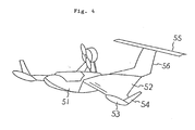
- FIG. 4 Representative one of the ground-surface-effect wing crafts in the prior art is illustrated in Fig. 4.
- the ground-surface-effect wing craft is contemplated, as is generally known, such that it is made to fly closely to the water surface or the ground surface to bring about the condition where a pressure of an airflow along the lower surface of a wing is raised by the ground-surface-effect caused by approach to the ground surface, and to thereby increase a lift.
- the ground-surface-effect wing craft in the prior art had a configuration similar to an aeroplane in its general shape, in which a main body 51 is formed as a fuselage, a wing 52 is formed as a main wing, and the craft has conventional horizontal 55 and vertical 56 tail surfaces.
- a ground-surface-effect wing craft is known from the document DE-B2-2 547 945.
- a Lippisch wing is employed as the wing 52, and at the ends of the wings are equipped floats 53 and V-shaped direction-stabilizer plates 54, the area of the wing being enlarged as compared to the conventional aeroplane.
- a floatable speed in contrast to the fact that generally a floatable speed is said to be about 100 km/hr in the case of a light craft such as Cessna craft, it can be reduced to 50 - 60 km/hr in the case of the subject craft.
- the clearance between the wing and the ground is about 1/10 x chord length (wing span), and if the left and right wings are subjected to waves in an irregular manner when the craft glides, for instance, above the water surface, then a possibility of breaking balance is very high.
- a ground-surface-effect wing craft comprising a main body having an aerofoil shape, end plates provided nearly vertically at the opposite lateral ends of the main body for preventing air from flowing outwards from the underside of the main body, end plate floats provided at the end plates, a float provided at a central lower portion of the main body, an operator's seat provided on the float, vertical and horizontal tail surface provided at a rear portion of the main body, and propelling means for lifting and propelling the ground-surface-effect wing craft by making use of a ground-surface-effect generated between the main body and a flat surface such as a water surface or a ground surface.
- the end plate floats In addition, as a result of mounting of the end plate floats to the end plates, while they do not act to generate an underwater drag under a static condition because the end plate floats are not submerged under the water surface, in response to rolling, since the end plate float on the starboard side are submerged in the water in correspondence to the rolling angle (tilting angle) in the case of tilting to the starboard side, the weight of water of the submerged volume acts as a buoyancy for the float, thus raises the starboard side of the main body and corrects the tilting angle.
- the height of the end plates is determined so as to supplement a lift coefficient upon take-off from the water surface.
- the main body generally has an aerofoil shape, if it is propelled by the propelling means, the craft is lifted and propelled by a lift generated due to the aerofoil shape and an aerodynamic force of air filled under the main body due to the end plates and the main body.
- reference numeral 1 designates a main body generally formed in an aerofoil shape, which constitutes a main wing.
- This main body 1 is equipped with a cockpit 4 at a central portion, a float 3 at the bottom of an airframe, end plates 2 at its opposite ends for preventing air under the main body 1 from escaping outwards, and a propelling engine 5, a propeller 6, a vertical tail 7 and a horizontal tail 8 at a rear portion.
- the main body has a unitary aerofoil shape adapted to generate a lift for take-off, and its shape and area are determined on the basis of a take-off speed, a weight of the craft and a lift coefficient.
- a principal material of the portion forming the aerofoil shape of the main body carbon FRP that is light in weight and subjected to waterproofing, is used, and the molded shape is an integral shape (a monocoque shape).
- Reference numeral 2 designates end plates hanging from the opposite ends of the main wing forming the main body 1 up to the water surface or the ground surface. It is molded of the same material as the main body 1 into an integral shape with the main body 1. These end plates 2 are provided in order that upon navigation, air flowing from the forth of the main body 1 to the underside of the main wing may not be allowed to escape sideways, and thereby the air flow flows out from the rear of the main wing.
- the lower surfaces (lower edges) of the end plates 2 are made to be flush with (or positioned a little above) a plane connecting a corner edge of a front step 11 as will be described later and a corner edge of a rear step 12 as will be described later, to make use of the ground-surface-effect to a maximum extent. Also, attention is paid so that the lower surfaces of the end plates 2 may not protrude to the lower side of the aforementioned plane for the purpose of not increasing an underwater drag. It is to be noted that the end plate 2 is constructed of a thick plate portion 2a and a thin plate portion 2b.
- Reference numeral 3 designates a float provided at the bottom of the main body 1, and it is a float capable of generating a buoyancy compatible to a total weight of the main body 1. It is preferable to design the float 3 so that its total volume may generate a buoyancy about three times as large as the total weight of the main body 1.
- the front portion of the float 3 is formed in a chine shape similarly to a bow of normal ships, and the bottom surface is formed in such shape that an underwater drag such as a frictional resistance, a wave making resistance or the like may be minimized.
- the front step 11 and the rear step 12 formed on the float 3 Upon alighting on the water surface after take-off of the main body 1, the front step 11 and the rear step 12 formed on the float 3 would separately come into contact with the water, and thereby impact against the water surface can be mitigated.
- the material of the float 3 is foamed styrol having its surface reinforced by carbon FRP in order to achieve lightweight construction.
- the float 3 could be formed integrally with a cabin 22.
- Reference numeral 4 designates a cockpit provided at a central portion of the main body 1.
- This cockpit 4 is provided either by forming the cabin 22 integrally with the main body 1, or by forming the cabin 22 with the main body 1 and the float 3.
- the cockpit 4 consists of a seat 16 for an operator, an engine start/stop switch, an engine tachometer, an atmospheric speed meter, a water temperature meter, and the like.
- a meter panel 17, an engine throttle lever 18, an elevator control stick 19, a pedal 20 for controlling a rudder and an underwater rudder and the like are equipped.
- Reference numeral 5 designates a propelling engine mounted to a rear portion of the main body 1.
- This propelling engine 5 is mounted to the main body 1 via an engine frame and it serves as a propelling power source for the main body 1. It drives a propeller 6 via a pulley by means of a driving shaft not specifically referred to.
- This propelling engine 5 is installed in an upsidedown attitude in order to set a center of gravity of the airframe low.
- Reference numeral 6 designates a propeller which is driven by the propelling engine 5 via a pulley, and it generates a thrust.
- the propeller 6 is a variable-pitch propeller having four blades.
- the propeller pitch is adjusted so as to match with an engine power.
- a reaction torque generated by the propeller 6 is regulated by giving a difference between the areas of the left and right parts of an elevator 15 of a horizontal tail 8 provided at a rear portion of the main body 1, or by giving an offset to an angle of attack upon balancing. Regulation by means of a balance weight is not favorable because a total weight increases.
- Reference numeral 7 designates a vertical tail surface provided at a rear portion of the main body 1.
- the vertical tail surface 7 consists of fixed portions and a movable portion.
- the fixed portions are provided one on each of the opposite sides of the rear portion of the main body 1.
- the movable portion is provided one at the center of the rear portion of the main body 1 and forms a rudder 13.
- the fixed portions of the vertical tail surface 7 serve to realize stability in a straight traveling property of the craft, and in order to reduce resistance upon turning, a cut-away portion 23 is provided for appropriately adjusting its area by cutting away at least 1/4 - 1/3 of the vertical tail frame of the fixed portion, and the remainder is formed of cloth or plate such as polyester to form a vertical tail area of the fixed portion.
- the rudder 13 at the movable portion is linked with an underwater rudder 9 and serves as a steering member.
- cloth such as polyester fibers is woven on a framework of aluminium pipes, and thereby realization of lightweight construction is achieved.
- Reference numeral 8 designates a horizontal tail surface provided at a rear portion of the main body 1.
- the horizontal tail surface 8 is composed of a stabilizer 14 and an elevator 15.
- the structure of the horizontal tail surface 8 is constructed by similar materials and working methods to the vertical tail surface 7.
- the stabilizer 14 is of semi-fixed type, and has such structure that an angle of attack can be preset. Longitudinal stabilization of an airframe is effected by presetting of the angle of attack of this stabilizer 14 and manipulation of the elevator 15. For instance, the angle of attack of the stabilizer 14 is semi-fixed in the ranges of 10 - 15 degrees respectively above and under based on the height of the center of the propeller 6, and a minimum adjustable angle is made to be 1.5 - 3.0 degrees.
- an attack angle adjusting ruler having 10 - 20 point holes is provided on a fixed portion vertical tail frame of the vertical tail surface 7.
- a structure of the elevator 15 is such that its attack angle can be adjusted in the ranges of 15 - 20 degrees respectively above and under. In this way, the attack angles of the stabilizer 14 and the elevator 15 are made individually adjustable.
- attack angles are preferable angles obtained as a result of experiments, and if the attack angles become too large, in the case of navigation, the plane body would be subjected to abrupt variations, rise and fall of a nose would become large, and so, it is unfavorable. However, if the attack angles are too small, variation of the craft body is gradual, and so, control of the craft body would be difficult and a run-up distance would become long.
- Reference numeral 9 designates an underwater rudder provided at the rear side of the float 3 and mounted to the bottom of the main body 1.
- the underwater rudder 9 is operated as linked with the rudder 13 via a push-pull wire by a rudder and underwater rudder control pedal 20 at the operator's seat 4.
- the underwater rudder 9 is adjustable in vertical positions along a support rod in correspondence to a trim angle of the main body 1. A submerged depth of the underwater rudder 9 when the craft is stationary on the water, is adjusted so that an underwater drag upon take-off from the water may be minimized and upon flying the underwater rudder 9 may not come into contact with the water.
- the material of the underwater rudder 9 is aluminium material.
- Reference numeral 10 designates end plate floats mounted to the end plates 2.
- the end plate floats 10 are provided for the purpose of enhancing longitudinal stability and lateral stability of the main body 1.
- a buoyancy is generated according to a submerged volume of the end plate floats 10, this buoyancy serves as a restoring force, and it tends to restore the main body 1 to the original stable condition.
- the main body 1 tilts to the starboard side, hence the end plate 10 on the starboard side will submerge in the water, a buoyancy will be generated in correspondence to the submerged volume, and it serves as a restoring force and acts to restore the starboard to the original state. This results in enhancement of lateral stability.
- the material of the end plate float 10 is similar to that of the float 3.
- the height of the mount position of the end plate float 10 to the end plate 2 is made higher than a still water draught line, and it is preferable to mount it about 10 - 20 m/m above the draught line. Thereby, an underwater drag caused by the end plate float 10 upon navigation on the water surface can be reduced.
- Reference numeral 11 designates a front step provided at a central portion of the bottom surface of the float 3. This facilitates cutting of water during the period when the main body 1 starts from the state held in contact with the water and finishes take-off from the water, and thereby reduces an underwater drag.
- the front step 11 is designed so as to support a center of gravity of the main body, and the cutting depth of the front step 11 is preferably 10% or less of the width of the float 3. For instance, if the width of the float 3 is 800 m/m, then the cutting depth of the step is preferably 80 m/m or less.
- Reference numeral 12 designates a cut-off at a rear portion of the bottom surface of the float 3, that is, a rear step.
- a plane connecting a corner edge of the front step 11 and a corner edge of the rear step 12 becomes a contact plane with the water surface upon float-up, and an angle formed between a reference plane of the main wing of the main body 1 and said plane connecting the corner edges of the steps 11, 12 becomes an angle of attack of the main body 1 upon take-off from the water.
- the rear step 12 is separated from the underwater rudder 9 by 300 m/m or more, but when the interval therebetween is small, a tunnel-shaped notch serving as a water-flow passageway is provided at a central portion of the rear step 12.
- Reference numeral 13 designates a rudder forming a vertical tail surface 7.
- the rudder 13 is operated as linked with the underwater rudder 9.
- the construction is such that for turning of the main body 1, the underwater rudder 9 achieves a principal effect upon navigation on the water surface, but when a speed rises and an airflow behind a propeller becomes active, or when the main body floats up, the draught becomes shallow and the effect of the underwater rudder 9 becomes weak, the rudder 13 achieves a principal effect.
- Reference numeral 14 designates a stabilizer forming a horizontal tail surface 8. It is mounted horizontally at an upper portion of the vertical tail surface 7 and in front of an elevator 15, and in order to effectively utilize a rear airflow of the propeller 6 as a PAR (Power Argumented Ramwing), it is desirable to make the height of the stabilizer 14 nearly coincide with the height of the center of the propeller 6.
- the interval between the front edge of the stabilizer 14 and the propeller 6 is preferably about 100 m/m in view of facility of dismounting and maintenance of the propeller 6. If they are separated too far, the PAR effect becomes weak. Since the angle of attack of the stabilizer 14 can be preset, it is adjusted while observing a navigation condition so that stability can be established in the longitudinal direction.
- Reference numeral 15 designates an elevator forming the horizontal tail surface 8.
- the elevator 15 is constructed of respective ones on the left and on the right, and it is used for aileron operations upon nose-up, nosed-down and turning of the main body 1. After longitudinal stabilization of the main body 1 has been adjusted by the stabilizer 14, if the elevator 15 is operated downwards, then nose-down would occur, while if it is operated upwards, then nose-up would occur. If the elevator 15 is operated upwards on the right side and operated downwards on the left side, then an aileron operation would occur. If it is operated downwards on the right side and operated upwards on the left side, then likewise an aileron operation would occur. In order to reduce a reaction torque of the propeller 6, the areas of the left and right sections of the elevator 15 are made different, or the mount angles thereof under a balanced condition are made to have an offset.
- Reference numeral 16 designates an operator's seat.
- the seat 16 has a structure movable by about 100 m/m in the back and forth directions, and this is for the purpose of finely adjusting the position of a center of gravity and matching with the operator's attitude.
- Reference numeral 17 designates a meter panel consisting of an engine start/stop switch, an engine tachometer, an atmospheric speed meter, a water temperature meter, and the like for operating the main body 1.
- Reference numeral 18 designates a throttle lever for controlling an engine, which is provided on the port side of the cockpit 4.
- the throttle lever 18 is connected to a valve in a carburettor via a push-pull wire not shown, an opening angle of the valve in the carburettor is adjusted by operations of the throttle lever 18, and while monitoring the engine tachometer, the rotational speed of the engine is set at a predetermined value.
- Reference numeral 19 designates a stick lever for controlling the elevator, which is provided at the center of the driver's seat 16 in the cockpit 4. If the stick lever 19 is pulled towards the operator, it becomes an elevator-up operation and nose-up of the main body 1 becomes possible, while if the stick lever 19 is pushed forth, it becomes an elevator-down operation and nose-down becomes possible. If the stick lever 19 is operated leftwards or rightwards, the elevator 15 is subjected to aileron operations.
- Reference numeral 20 designates a pedal for controlling the rudder 13 and the underwater rudder, which is present in front of the operator's seat 16.
- the pedal 20 consists of respective ones for right foot use and for left foot use as connected with each other, and upon turning to the left, if the right foot pedal is trampled forth, then the left foot pedal is moved towards the operator, and the rudder 13 and the underwater rudder 9 are jointly operated. Upon turning to the right, if the left foot pedal is trampled forth, similar operations would occur.
- Reference numeral 21 designates end plate support rods for reinforcing the end plates 2.
- the end plate support rods 21 are provided so as to counteract against the stress of the end plates 2 exerted by a lateral wind and lateral waves or upon turning.
- the end plate support rods 21 should have a configuration for which an air resistance becomes minimum.
- nose-up is effected by elevator-up, a trim angle is selected sufficiently large, and thereby take-off from the water can be made early. It is also possible that during gliding, nose-down is effected by elevator-down and the height of take-off from the water is held. If the speed is reduced from the gliding condition, the main body 1 would alight on the water quietly and would continue navigation on the water surface. When the operation has been finished, the engine is stopped.
- the craft according to the present invention can reach ram wing gliding safely and quickly.
- the inconvenience that the end plate or the like on the side of banking may come into contact with the water is eliminated, easiness of turning and stability upon gliding are increased, and a ground-surface-effect wing craft having high degree of usefulness can be provided.
Landscapes
- Engineering & Computer Science (AREA)
- Aviation & Aerospace Engineering (AREA)
- Transportation (AREA)
- Mechanical Engineering (AREA)
- Toys (AREA)
Claims (8)
- Bodeneffekt-Fluggerät mit einem Hauptkörper (1) einer strömugnsgünstigen Form oder Tragflächenform, nahezu lotrecht an den gegenüberliegenden Querenden des Hauptkörpers angeordneten Endscheiben (2) zur Verhinderung einer Luftströmung von der Unterseite des Hauptkörpers nach außen, an den Endscheiben vorgesehenen Endscheiben-Schwimmern (10), einem am mittleren unteren Abschnitt des Hauptkörpers vorgesehenen Schwimmer (3), einem auf dem Schwimmer vorgesehenen Führersitz (16), am hinteren Abschnitt des Hauptkörpers vorgesehenen lotrechten (7) und waagerechten (8) Leitflächen sowie einer Vortriebseinrichtung (5, 6) für Auftrieb und Vortrieb des Bodeneffekt-Fluggeräts unter Ausnutzung eines zwischen dem Hauptkörper und einer flachen Fläche, wie einer Wasser- oder Bodenoberfläche, erzeugten Bodeneffekts.
- Bodeneffekt-Fluggerät nach Anspruch 1, dadurch gekennzeichnet, daß ein mit einem in der lotrechten Leitfläche (7) angeordneten Ruder (13) gekoppelt betätigbares Unterwasserruder (9) vorgesehen ist.
- Bodeneffekt-Fluggerät nach Anspruch 1, dadurch gekennzeichnet, daß die waagerechte Leitfläche (8) aus einer Dämpfungsflosse (14) und einem Höhenruder (15) gebildet ist und daß die Dämpfungsflosse in einer Stellung angeordnet ist, in welcher sie einen Abstrom von der Vortriebseinrichtung abzunehmen vermag.
- Bodeneffekt-Fluggerät nach Anspruch 1, dadurch gekennzeichnet, daß die Endscheiben-Schwimmer oberhalb einer Wasserlinie angeordnet sind.
- Bodeneffekt-Fluggerät nach Anspruch 1, dadurch gekennzeichnet, daß an einem zentralen Abschnitt der Unterseite des Schwimmers (3) eine Aufwärtsstufe (11) vorgesehen ist.
- Bodeneffekt-Fluggerät nach Anspruch 5, dadurch gekennzeichnet, daß an einem hinteren Abschnitt der Unterseite des Schwimmers (3) ferner eine Aufwärtsstufe (12) vorgesehen ist.
- Bodeneffekt-Fluggerät nach Anspruch 6, dadurch gekennzeichnet, daß die Unterseiten der Endscheiben mit einer die Eckkanten der beiden Stufen der Unterseite des Schwimmers verbindenden Ebene bündig abschließend oder etwas oberhalb dieser Ebene liegend angeordnet sind.
- Bodeneffekt-Fluggerät nach Anspruch 1, dadurch gekennzeichnet, daß durch den Hauptkörper (1) und den Schwimmer (3) eine Kabine (22) einheitlich gebildet ist.
Applications Claiming Priority (4)
| Application Number | Priority Date | Filing Date | Title |
|---|---|---|---|
| JP196507/89 | 1989-07-31 | ||
| JP19650789 | 1989-07-31 | ||
| JP21206/90 | 1990-01-31 | ||
| JP2120690A JPH03128757A (ja) | 1989-07-31 | 1990-01-31 | 地面効果翼機 |
Publications (2)
| Publication Number | Publication Date |
|---|---|
| EP0411358A1 EP0411358A1 (de) | 1991-02-06 |
| EP0411358B1 true EP0411358B1 (de) | 1993-09-29 |
Family
ID=26358238
Family Applications (1)
| Application Number | Title | Priority Date | Filing Date |
|---|---|---|---|
| EP90113277A Expired - Lifetime EP0411358B1 (de) | 1989-07-31 | 1990-07-11 | Bodeneffekt-Fluggerät |
Country Status (4)
| Country | Link |
|---|---|
| US (1) | US5065833A (de) |
| EP (1) | EP0411358B1 (de) |
| AU (1) | AU625387B2 (de) |
| DE (2) | DE69003622T2 (de) |
Families Citing this family (11)
| Publication number | Priority date | Publication date | Assignee | Title |
|---|---|---|---|---|
| US5636702A (en) * | 1994-06-09 | 1997-06-10 | Kolacny; Gordon S. | Aerodynamic and ground effect craft |
| US6343768B1 (en) | 2000-05-16 | 2002-02-05 | Patrick John Muldoon | Vertical/short take-off and landing aircraft |
| CA2331944A1 (en) * | 2001-01-19 | 2002-07-19 | Ray Richards | Seaplane having main wing mounted beneath fuselage |
| US6398158B1 (en) | 2001-06-22 | 2002-06-04 | The United States Of America As Represented By The Secretary Of The Navy | High altitude low flying platform hull |
| US7334756B2 (en) * | 2002-07-22 | 2008-02-26 | Rollan Gurgenovich Martirosov | Ground-effect craft and method for the cruising flight thereof |
| US7148797B2 (en) * | 2004-07-23 | 2006-12-12 | Innovalarm Corporation | Enhanced fire, safety, security and health monitoring and alarm response method, system and device |
| US7398740B2 (en) * | 2005-01-26 | 2008-07-15 | Boncodin Franz B | Multi-mission/purpose ground-effect craft derived from a common modular platform |
| WO2007130653A2 (en) * | 2006-05-04 | 2007-11-15 | Mattel, Inc. | Flying toy vehicle |
| US8348714B2 (en) * | 2008-05-30 | 2013-01-08 | Mattel, Inc. | Toy flying aircraft |
| US9540998B2 (en) | 2011-05-27 | 2017-01-10 | Daniel K. Schlak | Integral gas turbine, flywheel, generator, and method for hybrid operation thereof |
| US11186185B2 (en) * | 2017-05-31 | 2021-11-30 | Textron Innovations Inc. | Rotor brake effect by using electric distributed anti-torque generators and opposing electric motor thrust to slow a main rotor |
Family Cites Families (10)
| Publication number | Priority date | Publication date | Assignee | Title |
|---|---|---|---|---|
| US2214945A (en) * | 1937-07-31 | 1940-09-17 | Cons Aircraft Corp | Retractable hydrovane |
| US3208421A (en) * | 1963-08-20 | 1965-09-28 | Wesley K Landes | Aircraft floats |
| DE1813311B1 (de) * | 1968-12-07 | 1970-07-23 | Lippisch Dr Alexander M | Tragfluegelanordnung fuer ein Fahrzeug zur Bewegung auf dem Lande bzw. dem Wasser und in der Luft |
| AU406242B2 (en) * | 1969-03-27 | 1970-09-21 | Air cushion vehicle | |
| DE2205952C3 (de) * | 1972-02-09 | 1981-12-24 | Vereinigte Flugtechnische Werke Gmbh, 2800 Bremen | Tragflügel für Stauflügelfahrzeuge |
| DE2547945C3 (de) * | 1975-10-27 | 1978-10-12 | Rhein-Flugzeugbau Gmbh, 4050 Moenchengladbach | Tragflügel für ein Stauflügelfahrzeug |
| DE2606405A1 (de) * | 1976-02-18 | 1977-08-25 | Ver Flugtechnische Werke | Staufluegelfahrzeug |
| DE3522146A1 (de) * | 1984-08-01 | 1986-02-13 | Albert 5204 Lohmar Blum | Bodeneffekt-fahrzeug |
| US4709879A (en) * | 1985-04-24 | 1987-12-01 | Stafford Lannon F | Controlled air-flow aircraft capable of vertical flight |
| DE295652T1 (de) * | 1987-06-16 | 1989-05-11 | Mitsubishi Jukogyo K.K., Tokio/Tokyo, Jp | Flugzeug mit bodeneffekt-fluegeln. |
-
1990
- 1990-07-11 DE DE90113277T patent/DE69003622T2/de not_active Expired - Fee Related
- 1990-07-11 DE DE199090113277T patent/DE411358T1/de active Pending
- 1990-07-11 EP EP90113277A patent/EP0411358B1/de not_active Expired - Lifetime
- 1990-07-19 US US07/556,253 patent/US5065833A/en not_active Expired - Fee Related
- 1990-07-30 AU AU59980/90A patent/AU625387B2/en not_active Ceased
Also Published As
| Publication number | Publication date |
|---|---|
| AU5998090A (en) | 1991-01-31 |
| DE69003622T2 (de) | 1994-02-24 |
| DE411358T1 (de) | 1991-07-04 |
| US5065833A (en) | 1991-11-19 |
| EP0411358A1 (de) | 1991-02-06 |
| DE69003622D1 (de) | 1993-11-04 |
| AU625387B2 (en) | 1992-07-09 |
Similar Documents
| Publication | Publication Date | Title |
|---|---|---|
| US3761041A (en) | Lifting body aircraft | |
| US3908783A (en) | Winged surface effect vehicle | |
| EP0411358B1 (de) | Bodeneffekt-Fluggerät | |
| US3661111A (en) | Aerofoilboat | |
| US6014940A (en) | Surface effect craft | |
| US3762355A (en) | Water craft with aerodynamic lift | |
| US7040574B2 (en) | Aircraft and watercraft adapted to float on main wing | |
| US5277383A (en) | Amphibian aircraft | |
| US3987982A (en) | Wind-powered flying boat | |
| US4615291A (en) | Hydrofoil boat | |
| US5020740A (en) | Pitch control trimming system for canard design aircraft | |
| US5082198A (en) | Recreational flying vehicle | |
| US5314035A (en) | Surface effect vehicle | |
| US6230835B1 (en) | Ground effect vehicle | |
| US3424120A (en) | Hydrotunnel boat | |
| US3118411A (en) | Aero-glide boat | |
| US6581536B1 (en) | Surface effect watercraft having airfoil-augmented lift | |
| US5181674A (en) | Wind driven craft | |
| US3522785A (en) | Semiairborne vehicle | |
| US5526764A (en) | Surface effect craft | |
| US4781341A (en) | Flying wing aircraft | |
| JPH02503302A (ja) | 傾斜防止揚力装置を備えた帆走艇 | |
| JPH04228353A (ja) | 翼付き船 | |
| JPH03128757A (ja) | 地面効果翼機 | |
| US6964240B1 (en) | Hull for high speed water craft |
Legal Events
| Date | Code | Title | Description |
|---|---|---|---|
| PUAI | Public reference made under article 153(3) epc to a published international application that has entered the european phase |
Free format text: ORIGINAL CODE: 0009012 |
|
| 17P | Request for examination filed |
Effective date: 19900808 |
|
| AK | Designated contracting states |
Kind code of ref document: A1 Designated state(s): DE FR GB SE |
|
| EL | Fr: translation of claims filed | ||
| RIN1 | Information on inventor provided before grant (corrected) |
Inventor name: SATAKE, TOKUKI, C/O KOBE SHIPYARD & ENGINE WORKS Inventor name: HIGASHIDA, AKIO, C/O KOBE SHIPYARD & ENGINE WORKS Inventor name: MATSUOKA, TOSHIO, C/O KOBE SHIPYARD & ENGINE WORKS |
|
| DET | De: translation of patent claims | ||
| 17Q | First examination report despatched |
Effective date: 19921123 |
|
| GRAA | (expected) grant |
Free format text: ORIGINAL CODE: 0009210 |
|
| AK | Designated contracting states |
Kind code of ref document: B1 Designated state(s): DE FR GB SE |
|
| ET | Fr: translation filed | ||
| REF | Corresponds to: |
Ref document number: 69003622 Country of ref document: DE Date of ref document: 19931104 |
|
| PLBE | No opposition filed within time limit |
Free format text: ORIGINAL CODE: 0009261 |
|
| STAA | Information on the status of an ep patent application or granted ep patent |
Free format text: STATUS: NO OPPOSITION FILED WITHIN TIME LIMIT |
|
| 26N | No opposition filed | ||
| EAL | Se: european patent in force in sweden |
Ref document number: 90113277.9 |
|
| PGFP | Annual fee paid to national office [announced via postgrant information from national office to epo] |
Ref country code: GB Payment date: 19950630 Year of fee payment: 6 |
|
| PGFP | Annual fee paid to national office [announced via postgrant information from national office to epo] |
Ref country code: DE Payment date: 19950710 Year of fee payment: 6 |
|
| PGFP | Annual fee paid to national office [announced via postgrant information from national office to epo] |
Ref country code: FR Payment date: 19950711 Year of fee payment: 6 |
|
| PGFP | Annual fee paid to national office [announced via postgrant information from national office to epo] |
Ref country code: SE Payment date: 19950717 Year of fee payment: 6 |
|
| PG25 | Lapsed in a contracting state [announced via postgrant information from national office to epo] |
Ref country code: GB Effective date: 19960711 |
|
| PG25 | Lapsed in a contracting state [announced via postgrant information from national office to epo] |
Ref country code: SE Effective date: 19960712 |
|
| GBPC | Gb: european patent ceased through non-payment of renewal fee |
Effective date: 19960711 |
|
| PG25 | Lapsed in a contracting state [announced via postgrant information from national office to epo] |
Ref country code: FR Effective date: 19970328 |
|
| PG25 | Lapsed in a contracting state [announced via postgrant information from national office to epo] |
Ref country code: DE Effective date: 19970402 |
|
| EUG | Se: european patent has lapsed |
Ref document number: 90113277.9 |
|
| REG | Reference to a national code |
Ref country code: FR Ref legal event code: ST |