EP0411296A1 - Drive device of a vehicle - Google Patents
Drive device of a vehicle Download PDFInfo
- Publication number
- EP0411296A1 EP0411296A1 EP90111732A EP90111732A EP0411296A1 EP 0411296 A1 EP0411296 A1 EP 0411296A1 EP 90111732 A EP90111732 A EP 90111732A EP 90111732 A EP90111732 A EP 90111732A EP 0411296 A1 EP0411296 A1 EP 0411296A1
- Authority
- EP
- European Patent Office
- Prior art keywords
- oil
- drive device
- float valve
- collecting space
- protective member
- Prior art date
- Legal status (The legal status is an assumption and is not a legal conclusion. Google has not performed a legal analysis and makes no representation as to the accuracy of the status listed.)
- Granted
Links
Images


Classifications
-
- F—MECHANICAL ENGINEERING; LIGHTING; HEATING; WEAPONS; BLASTING
- F16—ENGINEERING ELEMENTS AND UNITS; GENERAL MEASURES FOR PRODUCING AND MAINTAINING EFFECTIVE FUNCTIONING OF MACHINES OR INSTALLATIONS; THERMAL INSULATION IN GENERAL
- F16H—GEARING
- F16H57/00—General details of gearing
- F16H57/04—Features relating to lubrication or cooling or heating
- F16H57/042—Guidance of lubricant
- F16H57/0421—Guidance of lubricant on or within the casing, e.g. shields or baffles for collecting lubricant, tubes, pipes, grooves, channels or the like
-
- C—CHEMISTRY; METALLURGY
- C23—COATING METALLIC MATERIAL; COATING MATERIAL WITH METALLIC MATERIAL; CHEMICAL SURFACE TREATMENT; DIFFUSION TREATMENT OF METALLIC MATERIAL; COATING BY VACUUM EVAPORATION, BY SPUTTERING, BY ION IMPLANTATION OR BY CHEMICAL VAPOUR DEPOSITION, IN GENERAL; INHIBITING CORROSION OF METALLIC MATERIAL OR INCRUSTATION IN GENERAL
- C23C—COATING METALLIC MATERIAL; COATING MATERIAL WITH METALLIC MATERIAL; SURFACE TREATMENT OF METALLIC MATERIAL BY DIFFUSION INTO THE SURFACE, BY CHEMICAL CONVERSION OR SUBSTITUTION; COATING BY VACUUM EVAPORATION, BY SPUTTERING, BY ION IMPLANTATION OR BY CHEMICAL VAPOUR DEPOSITION, IN GENERAL
- C23C22/00—Chemical surface treatment of metallic material by reaction of the surface with a reactive liquid, leaving reaction products of surface material in the coating, e.g. conversion coatings, passivation of metals
- C23C22/05—Chemical surface treatment of metallic material by reaction of the surface with a reactive liquid, leaving reaction products of surface material in the coating, e.g. conversion coatings, passivation of metals using aqueous solutions
- C23C22/06—Chemical surface treatment of metallic material by reaction of the surface with a reactive liquid, leaving reaction products of surface material in the coating, e.g. conversion coatings, passivation of metals using aqueous solutions using aqueous acidic solutions with pH less than 6
- C23C22/07—Chemical surface treatment of metallic material by reaction of the surface with a reactive liquid, leaving reaction products of surface material in the coating, e.g. conversion coatings, passivation of metals using aqueous solutions using aqueous acidic solutions with pH less than 6 containing phosphates
- C23C22/08—Orthophosphates
- C23C22/12—Orthophosphates containing zinc cations
- C23C22/16—Orthophosphates containing zinc cations containing also peroxy-compounds
-
- C—CHEMISTRY; METALLURGY
- C23—COATING METALLIC MATERIAL; COATING MATERIAL WITH METALLIC MATERIAL; CHEMICAL SURFACE TREATMENT; DIFFUSION TREATMENT OF METALLIC MATERIAL; COATING BY VACUUM EVAPORATION, BY SPUTTERING, BY ION IMPLANTATION OR BY CHEMICAL VAPOUR DEPOSITION, IN GENERAL; INHIBITING CORROSION OF METALLIC MATERIAL OR INCRUSTATION IN GENERAL
- C23C—COATING METALLIC MATERIAL; COATING MATERIAL WITH METALLIC MATERIAL; SURFACE TREATMENT OF METALLIC MATERIAL BY DIFFUSION INTO THE SURFACE, BY CHEMICAL CONVERSION OR SUBSTITUTION; COATING BY VACUUM EVAPORATION, BY SPUTTERING, BY ION IMPLANTATION OR BY CHEMICAL VAPOUR DEPOSITION, IN GENERAL
- C23C22/00—Chemical surface treatment of metallic material by reaction of the surface with a reactive liquid, leaving reaction products of surface material in the coating, e.g. conversion coatings, passivation of metals
- C23C22/05—Chemical surface treatment of metallic material by reaction of the surface with a reactive liquid, leaving reaction products of surface material in the coating, e.g. conversion coatings, passivation of metals using aqueous solutions
- C23C22/06—Chemical surface treatment of metallic material by reaction of the surface with a reactive liquid, leaving reaction products of surface material in the coating, e.g. conversion coatings, passivation of metals using aqueous solutions using aqueous acidic solutions with pH less than 6
- C23C22/07—Chemical surface treatment of metallic material by reaction of the surface with a reactive liquid, leaving reaction products of surface material in the coating, e.g. conversion coatings, passivation of metals using aqueous solutions using aqueous acidic solutions with pH less than 6 containing phosphates
- C23C22/08—Orthophosphates
- C23C22/18—Orthophosphates containing manganese cations
-
- C—CHEMISTRY; METALLURGY
- C23—COATING METALLIC MATERIAL; COATING MATERIAL WITH METALLIC MATERIAL; CHEMICAL SURFACE TREATMENT; DIFFUSION TREATMENT OF METALLIC MATERIAL; COATING BY VACUUM EVAPORATION, BY SPUTTERING, BY ION IMPLANTATION OR BY CHEMICAL VAPOUR DEPOSITION, IN GENERAL; INHIBITING CORROSION OF METALLIC MATERIAL OR INCRUSTATION IN GENERAL
- C23C—COATING METALLIC MATERIAL; COATING MATERIAL WITH METALLIC MATERIAL; SURFACE TREATMENT OF METALLIC MATERIAL BY DIFFUSION INTO THE SURFACE, BY CHEMICAL CONVERSION OR SUBSTITUTION; COATING BY VACUUM EVAPORATION, BY SPUTTERING, BY ION IMPLANTATION OR BY CHEMICAL VAPOUR DEPOSITION, IN GENERAL
- C23C22/00—Chemical surface treatment of metallic material by reaction of the surface with a reactive liquid, leaving reaction products of surface material in the coating, e.g. conversion coatings, passivation of metals
- C23C22/05—Chemical surface treatment of metallic material by reaction of the surface with a reactive liquid, leaving reaction products of surface material in the coating, e.g. conversion coatings, passivation of metals using aqueous solutions
- C23C22/06—Chemical surface treatment of metallic material by reaction of the surface with a reactive liquid, leaving reaction products of surface material in the coating, e.g. conversion coatings, passivation of metals using aqueous solutions using aqueous acidic solutions with pH less than 6
- C23C22/34—Chemical surface treatment of metallic material by reaction of the surface with a reactive liquid, leaving reaction products of surface material in the coating, e.g. conversion coatings, passivation of metals using aqueous solutions using aqueous acidic solutions with pH less than 6 containing fluorides or complex fluorides
- C23C22/36—Chemical surface treatment of metallic material by reaction of the surface with a reactive liquid, leaving reaction products of surface material in the coating, e.g. conversion coatings, passivation of metals using aqueous solutions using aqueous acidic solutions with pH less than 6 containing fluorides or complex fluorides containing also phosphates
-
- C—CHEMISTRY; METALLURGY
- C23—COATING METALLIC MATERIAL; COATING MATERIAL WITH METALLIC MATERIAL; CHEMICAL SURFACE TREATMENT; DIFFUSION TREATMENT OF METALLIC MATERIAL; COATING BY VACUUM EVAPORATION, BY SPUTTERING, BY ION IMPLANTATION OR BY CHEMICAL VAPOUR DEPOSITION, IN GENERAL; INHIBITING CORROSION OF METALLIC MATERIAL OR INCRUSTATION IN GENERAL
- C23C—COATING METALLIC MATERIAL; COATING MATERIAL WITH METALLIC MATERIAL; SURFACE TREATMENT OF METALLIC MATERIAL BY DIFFUSION INTO THE SURFACE, BY CHEMICAL CONVERSION OR SUBSTITUTION; COATING BY VACUUM EVAPORATION, BY SPUTTERING, BY ION IMPLANTATION OR BY CHEMICAL VAPOUR DEPOSITION, IN GENERAL
- C23C22/00—Chemical surface treatment of metallic material by reaction of the surface with a reactive liquid, leaving reaction products of surface material in the coating, e.g. conversion coatings, passivation of metals
- C23C22/73—Chemical surface treatment of metallic material by reaction of the surface with a reactive liquid, leaving reaction products of surface material in the coating, e.g. conversion coatings, passivation of metals characterised by the process
- C23C22/77—Controlling or regulating of the coating process
-
- F—MECHANICAL ENGINEERING; LIGHTING; HEATING; WEAPONS; BLASTING
- F01—MACHINES OR ENGINES IN GENERAL; ENGINE PLANTS IN GENERAL; STEAM ENGINES
- F01M—LUBRICATING OF MACHINES OR ENGINES IN GENERAL; LUBRICATING INTERNAL COMBUSTION ENGINES; CRANKCASE VENTILATING
- F01M1/00—Pressure lubrication
- F01M1/12—Closed-circuit lubricating systems not provided for in groups F01M1/02 - F01M1/10
-
- F—MECHANICAL ENGINEERING; LIGHTING; HEATING; WEAPONS; BLASTING
- F01—MACHINES OR ENGINES IN GENERAL; ENGINE PLANTS IN GENERAL; STEAM ENGINES
- F01M—LUBRICATING OF MACHINES OR ENGINES IN GENERAL; LUBRICATING INTERNAL COMBUSTION ENGINES; CRANKCASE VENTILATING
- F01M11/00—Component parts, details or accessories, not provided for in, or of interest apart from, groups F01M1/00 - F01M9/00
- F01M11/06—Means for keeping lubricant level constant or for accommodating movement or position of machines or engines
-
- F—MECHANICAL ENGINEERING; LIGHTING; HEATING; WEAPONS; BLASTING
- F01—MACHINES OR ENGINES IN GENERAL; ENGINE PLANTS IN GENERAL; STEAM ENGINES
- F01M—LUBRICATING OF MACHINES OR ENGINES IN GENERAL; LUBRICATING INTERNAL COMBUSTION ENGINES; CRANKCASE VENTILATING
- F01M11/00—Component parts, details or accessories, not provided for in, or of interest apart from, groups F01M1/00 - F01M9/00
- F01M11/0004—Oilsumps
- F01M2011/0037—Oilsumps with different oil compartments
- F01M2011/0041—Oilsumps with different oil compartments for accommodating movement or position of engines
Abstract
Description
Die Erfindung betrifft eine Antriebseinrichtung eines Fahrzeuges, mit einer Ölwanne an der Unterseite des Motor/Getriebe-Blockes, aus der mittels einer Servopumpe über eine Saugleitung mit in Saugrichtung öffnendem Rückschlagventil Öl einem Kreislauf zuführbar ist, und mit wenigstens einem Rotationskörper wie Zahnrad, Kettenrad, Schwungrad oder dergleichen, der bis in den Bereich unterhalb des maximalen Ölfüllniveaus der Ölwanne herunterreicht.The invention relates to a drive device of a vehicle, with an oil pan on the underside of the engine / transmission block, from which oil can be supplied to a circuit by means of a servo pump via a suction line with a check valve opening in the suction direction, and with at least one rotating body such as a gearwheel, sprocket, Flywheel or the like, which extends down to the area below the maximum oil fill level of the oil pan.
Bei einer solchen Antriebseinrichtung eines Fahrzeuges besteht das Problem darin, daß der bzw. die bis in den Bereich der Ölwanne bis unterhalb des maximalen Ölfüllniveaus herunterreichende(n) Rotationskörper mit während des Fahrbetriebes innerhalb der Ölwanne hin- und herplantschendem Öl beaufschlagt werden. Dieses unkontrolliert plantschende bzw. schwappende Öl stellt einen unkontrolliert auftretenden Widerstand für den Lauf des Rotationskörpers dar, so daß dessen Funktionsweise zum Teil sogar ganz erheblich beeinträchtigt sein kann. Letzteres wäre beispielsweise im Zusammenhang mit einem Schwungrad der Fall, das als Energiespeicher Teil einer Bremsenergie-Rückgewinnungseinrichtung ist. Ein solches Schwungrad sollte möglichst frei und ungehindert rotieren können und keinen energieverzehrenden Widerständen ausgesetzt sein. Bei einem solchen Schwungrad bestünde aber auch dann, wenn es in einem eigenen Gehäuse gelagert ist, die Gefahr, daß sich beispielsweise aus den Lagern austretendes Schmieröl oder aus anderen Quellen eindringendes Öl im Gehäuse sammelt und bei zu großer Menge den Lauf des Schwungrades behindern könnte.In such a drive device of a vehicle, the problem is that the rotating body (s) reaching down into the area of the oil pan to below the maximum oil fill level are acted upon by oil splashing back and forth within the oil pan during driving operation. This uncontrolled splashing or sloshing oil represents an uncontrolled resistance to the running of the rotating body, so that its operation can in some cases be considerably impaired. The latter would be the case, for example, in connection with a flywheel, which is part of a braking energy recovery device as an energy store. Such a flywheel should be able to rotate as freely and freely as possible and should not be exposed to energy-consuming resistors. With such a flywheel, however, even if it is stored in its own housing, there is a risk that, for example, lubricating oil escaping from the bearings or oil penetrating from other sources will collect in the housing and, if the quantity is too great, could hinder the running of the flywheel.
Es ist daher Aufgabe der Erfindung, eine Antriebseinrichtung mit Einzelmerkmalen der eingangs genannten Art so auszubilden, daß der Rotationskörper von Berührung mit Öl freigehalten wird.It is therefore an object of the invention to design a drive device with individual features of the type mentioned at the outset in such a way that the rotary body is kept free from contact with oil.
Diese Aufgabe ist erfindungsgemäß durch eine Antriebseinrichtung mit Merkmalen der im Anspruch 1 gekennzeichneten Art gelöst.This object is achieved by a drive device with features of the type characterized in
Durch das erfindungsgemäß dem Rotationskörper zugeordnete Schutz-Organ wird erreicht, daß zumindestens ein Großteil des in der Ölwanne während des Fahrbetriebes des Fahrzeuges hin- und herschwappenden Öles von einem in den Bereich der Ölwanne herunterreichenden Rotationskörper ferngehalten wird, so daß dessen einwandfreier, ungehinderter Lauf sichergestellt ist. Trotzdem in den Innenraum des Schutz-Organes, gegebenenfalls auch von anderen Quellen eindringendes Öl wird intern gesammelt und aus dem Schutz-Organ von Zeit zu Zeit durch die erfindungsgemäß des weiteren vorgesehenen Vorkehrungen abgesaugt. Auf diese Weise ist den aufgabengemäßen Zielsetzungen mit einfachsten Mitteln optimal Rechnung getragen.The protective member assigned to the rotating body according to the invention ensures that at least a large part of the oil sloshing back and forth in the oil pan during the driving operation of the vehicle is kept away from a rotating body that descends into the area of the oil pan, so that its proper, unimpeded running is ensured is. Nevertheless, oil penetrating into the interior of the protective member, possibly also from other sources, is collected internally and sucked out of the protective member from time to time by the measures further provided according to the invention. In this way, the objectives in accordance with the task are optimally taken into account with the simplest of means.
Vorteilhafte Ausgestaltungen und Einzelheiten der erfindungsgemäßen Lösung sind in den Unteransprüchen gekennzeichnet.Advantageous refinements and details of the solution according to the invention are characterized in the subclaims.
Nachstehend ist die erfindungsgemäße Lösung anhand der Zeichnung näher erläutert, wobei in jeder der vier Figuren ein Ausführungsbeispiel der Erfindung weitestgehend schematisiert dargestellt ist.The solution according to the invention is explained in more detail below with reference to the drawing, an exemplary embodiment of the invention being shown largely schematically in each of the four figures.
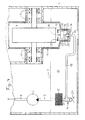
In den Figuren ist von der Antriebseinrichtung eines Fahrzeuges, z.B. Personenkraftwagen, Lastkraftwagen, Omnibus, Traktor, Bulldozer, Hubstapler, Kettenfahrzeug oder dergleichen, im wesentlichen nur jener Teil dargestellt, der durch die an der Unterseite des Motor/Getriebe-Blockes angeordnete Ölwanne 1 gebildet ist.In the figures, the drive device of a vehicle, e.g. Passenger cars, trucks, buses, tractors, bulldozers, forklifts, tracked vehicles or the like, essentially only that part is shown, which is formed by the
Aus der besagten Ölwanne 1 ist mittels einer Servopumpe 2 über eine Saugleitung 3 mit in Saugrichtung öffnendem Rückschlagventil 4 und nachfolgendem Filter 5 (nicht zwingend und auch nicht an dieser Stelle notwendig) Öl in einen Kreislauf pumpbar, der in der Zeichnung lediglich durch eine Förderleitung 6 angedeutet ist. Bei diesem Kreislauf kann es sich um einen Kühlölkreislauf, den Steuer- und/oder Arbeitskreislauf von Hydromaschinen als Teil eines hydrostatisch-mechanischen Leistungsverzweigungsgetriebes, eines Bremskreises oder der Servolenkung des Fahrzeuges handeln.From said
Aus Gründen einer höchst kompakten Bauweise reicht wenigstens ein Rotationskörper 7 als Teil der Antriebseinrichtung, wie Zahnrad, Kettenrad, Schwungrad oder dergleichen bis in den Bereich der Ölwanne 1 herunter, und zwar so weit, daß er mit seiner untersten Kante 8 unterhalb des mit 9 markierten maximalen Ölwannen-Füllniveaus liegt.For reasons of a highly compact design, at least one
Unter normalen Umständen würde der Rotationskörper 7 während der Fahrt des Fahrzeuges infolge der ständig hin- und herschwappenden bzw. plantschenden Ölfüllung 10 mit Öl angeschleudert, was seinen ordnungsgemäßen Lauf behindern, zumindest jedoch zu einem Wirkungsgradverlust führen könnte. Diesen Nachteilen wird dadurch erfindungsgemäß abgeholfen, daß demUnder normal circumstances, the rotating
Rotationskörper 7 ein ihn gegenüber der Ölfüllung 10 der Ölwanne 1 abschottendes sowie durch zumindest partielle Überdeckung seines unteren Bereiches gegen während der Fahrt plantschendes bzw. hin- und herschwappendes Öl schützendes Organ 11 und außerdem Vorkehrungen zum Sammeln und Absaugen von doch in den Innenraum des Schutz-Organs 11 eingedrungenem Öl zugeordnet sind. Dieses Schutz-Organ 11 kann nach Art einer nach oben hin offenen, nur den unteren Bereich des Rotationskörpers 7 bzw. der Rotationskörper 7 überdeckenden Schutzschale ausgebildet sein. Diese Ausführungsform ist aus den Figuren 1 bis 3 ersichtlich. Das Schutz-Organ 11 kann aber auch durch ein den die Rotationskörper 7 vollständig umgebendes, jedoch nicht hermetisch dichtes Gehäuse gebildet sein, welcher Fall aus Figur 4 ersichtlich ist. Nicht hermetisch dicht bedeutet, daß im Laufe der Zeit Öl, wenn auch in geringen Mengen, z.B. aus den Lagern 13 des Rotationskörpers 7 oder aus der Ölwanne 1 über besagte Lager 13 oder über Verbindungsstellen zwischen Gehäuseteilen, beispielsweise durch Kapillarwirkung, in den Innenraum des gehäuseförmigen Schutz-Organs 11 vordringen kann. Das das Schutzorgan 11 bildende Gehäuse ist durch nicht näher beschriebene Mittel in fester Zuordnung in Bezug auf die Ölwanne 1 gehalten - siehe Fig. 4.Rotating
Falls das Schutz-Organ 11 durch eine Schutzschale gebildet ist, so ist diese innerhalb der Ölwanne 1 derart angeordnet bzw., wenn als eigenständiges Bauteil vorgefertigt, in der Ölwanne 1 befestigt, daß sie mit ihrer Oberkante 12 ein größeres Stück über dem maximalen Ölwannen-Füllniveau 9 liegt. Das Maß zwischen Oberkante 12 der Schutzschale 11 und maximalem Ölwannen-Füllniveau 9 ist von Fall zu Fall unterschiedlich, durch Versuche zu ermitteln und dann so festzulegen, daß zumindest ein weitestgehendes Überschwappen des in der Ölwanne 1 bevorrateten Öles 10 in den Innenraum der Schutzschale 11 auch unter extremen Fahrbedingungen vermeidbar ist.If the
In den Innenraum des Schutz-Organes 11 trotzdem eingedrungenes Öl läuft an dessen Wandinnenfläche abwärts und wird in einem am untersten bzw. tiefsten Bereich des Schutz-Organes 11 ausgebildeten Sammelraum 14 gesammelt. Letzterer ist vorzugsweise durch eine topfförmige Ausbuchtung mit kreisringzylindrischer Seitenwand 15 und ebenem oder trichterförmigem Boden 16 gebildet.Oil that has nevertheless penetrated into the interior of the
An der tiefsten Stelle des Sammelraumes 14 ist ein bedarfsweise zu öffnender, normalerweise mittelbar verschlossener Auslaß 17 gegeben, an den eine Absaugleitung 18 angeschlossen ist. Als Mittel zum Schließen bzw. bedarfsweisen Öffnen des Sammelraum-Auslaßes 17 kann beispielsweise, wie in der Zeichnung dargestellt, ein Schwimmerventil 19 vorgesehen sein. Dessen Schwimmer 20 ist durch eine relativ dicke, runde Platte gebildet, die mit relativ großem Radialspiel im kreiszylindrischen Sammelraum 14 geführt ist. Das besagte Radialspiel muß mindestens so groß sein, daß das in den Innenraum des Schutz-Organes 11 eingedrungene Öl ungehindert in den Sammelraum 14 und dort in den Bereich unterhalb des Schwimmers 20 vordringen kann. An der Unterseite des Schwimmers 20 schließt sich als weiteres Teil des Schwimmerventiles 19 ein Schaft 21 mit Kugelkopf 22 an, der zum Verschließen des Auslasses 17 mit einem eingangs desselben gegebenen Ventilsitz 23 zusammenwirkt. Der Auslaß 17 des Sammelraumes 14 ist normalerweise durch das Schwimmerventil 19 dann geschlossen, wenn dieses durch sein Eigengewicht mit seinem Kugelkopf 22 auf dem Ventilsitz 23 aufsitzt und im Sammelraum 14 noch nicht genügend viel Öl gesammelt ist. Der Auslaß 17 wird jedoch dann geöffnet, wenn im Sammelraum 14 eine genügend große Ölmenge gesammelt ist und infolge der hierdurch bewirkten Auftriebskraft das Schwimmerventil 19 von seinem Ventilsitz 23 abgehoben wird. Sobald dies der Fall ist, kann eine Absaugung des gesammelten Öles mittels der Servopumpe 2 erfolgen und zwar über die Absaugleitung 18, die in den dargestellten Ausführungsbeispielen zur Saugleitung 3 hinführt und in diese im Bereich zwischen Rückschlagventil 4 und Filter 5 einmündet. Es ist dabei darauf zu achten, daß der Auslaß 17 des Sammelraumes 14 bzw. die Einmündungsstelle der Absaugleitung 18 in die Saugleitung 3 der Servopumpe 2 niveaumäßig höher als der Eintrittsbereich 24 der Saugleitung 3 liegt und das Gewicht des Schließorganes oder der hierauf einwirkenden Schließfeder des Rückschlagventiles 4 so ausgelegt ist, daß sich ein diese Öl-Absaugung aus den Sammelraum 14 ermöglichender Druckabfall in dem von der Servopumpe 2 aus der Ölwanne 1 durch die Saugleitung 3 geförderten Öl ergibt.At the lowest point of the
Des weiteren ist ein das Öffnen und Schließen des Schwimmerventiles 19 erfassender Sensor vorgesehen, der in dem Fall, wenn die Servopumpe 2 im Moment des Öffnens des Schwimmerventiles 19 inaktiv sein sollte, eine Inbetriebnahme der Servopumpe 2 und gegebenenfalls Wiederabschaltung desselben nach Schließen des Schwimmerventiles 19 auslöst. Dieser Sensor kann an geeigneter Stelle des Sammelraumes 14 oder des Schutz-Organes 11 angeordnet sein. Vorzugweise bildet der Sensor gleichzeitig einen den Öffnungshubweg des Schwimmerventiles 19 begrenzenden Anschlag 25, der in das Schutz-Organ 11 oberhalb des Sammelraumes 14 zwischen diesem und der Unterkante 8 des Rotationskörpers 7 eingebaut ist. Der Anschlag/Sensor 25 kann beispielsweise durch eine metallische Platte gebildet sein, die ein Teil eines kapazitiven Näherungsschalters bildet und über eine elektrische Signalleitung mit einer den Betrieb der Servopumpe 2 regelnden Steuereinrichtung verbunden ist.Furthermore, a sensor that detects the opening and closing of the
Claims (12)
Applications Claiming Priority (2)
| Application Number | Priority Date | Filing Date | Title |
|---|---|---|---|
| DE3925411 | 1989-08-01 | ||
| DE3925411A DE3925411A1 (en) | 1989-08-01 | 1989-08-01 | DRIVING DEVICE OF A VEHICLE |
Publications (2)
| Publication Number | Publication Date |
|---|---|
| EP0411296A1 true EP0411296A1 (en) | 1991-02-06 |
| EP0411296B1 EP0411296B1 (en) | 1992-09-02 |
Family
ID=6386270
Family Applications (1)
| Application Number | Title | Priority Date | Filing Date |
|---|---|---|---|
| EP90111732A Expired - Lifetime EP0411296B1 (en) | 1989-08-01 | 1990-06-21 | Drive device of a vehicle |
Country Status (2)
| Country | Link |
|---|---|
| EP (1) | EP0411296B1 (en) |
| DE (2) | DE3925411A1 (en) |
Cited By (1)
| Publication number | Priority date | Publication date | Assignee | Title |
|---|---|---|---|---|
| US11920671B1 (en) * | 2022-09-13 | 2024-03-05 | Dana Italia S.R.L. | Lubrication system with a flow regulating floater container |
Families Citing this family (8)
| Publication number | Priority date | Publication date | Assignee | Title |
|---|---|---|---|---|
| DE10017271A1 (en) * | 2000-04-06 | 2001-10-11 | Zahnradfabrik Friedrichshafen | Automatic gearbox has arrangement for reducing air component in oil-air dispersion in form of oscillation stimulator for oil in sump |
| DE102004060595C5 (en) * | 2004-12-09 | 2013-12-19 | Getrag Getriebe- Und Zahnradfabrik Hermann Hagenmeyer Gmbh & Cie Kg | Dual clutch assembly |
| JP5202596B2 (en) | 2010-09-15 | 2013-06-05 | 太平洋工業株式会社 | Oil pan tank valve structure |
| DE102011079824A1 (en) * | 2011-07-26 | 2013-01-31 | Zf Friedrichshafen Ag | Device for controlling and adjusting oil level in container e.g. oil sump, of automated transmission of motor vehicle, has intake valve closed during minimum oil level in container and completely opened during maximum oil level |
| DE102011080710A1 (en) * | 2011-08-10 | 2013-02-14 | Zf Friedrichshafen Ag | Hybrid gear box for motor car, has hybrid drive separated by partition wall or compartment from transmission oil sump, where partition wall exhibits cup-shaped structure and comprises bottom wall and cylinder wall |
| DE102014013580A1 (en) * | 2014-09-13 | 2016-03-17 | Daimler Ag | Motor vehicle transmission device |
| DE102019218418A1 (en) * | 2019-11-28 | 2021-06-02 | Zf Friedrichshafen Ag | Transmission for a motor vehicle |
| DE102022212783B3 (en) | 2022-11-29 | 2023-12-28 | Magna powertrain gmbh & co kg | Lubrication and cooling system and method for operating a lubrication and cooling system with emergency lubrication of an electric drive |
Citations (5)
| Publication number | Priority date | Publication date | Assignee | Title |
|---|---|---|---|---|
| FR502791A (en) * | 1916-03-30 | 1920-05-26 | Louis Renault | Improvements to engine lubrication systems |
| FR856123A (en) * | 1938-06-14 | 1940-05-30 | Daimler Benz Ag | Lubricating oil circulation for internal combustion engines |
| DE1908240A1 (en) * | 1969-02-19 | 1970-08-27 | Klaue Hermann | Dry sump lubrication system, especially for air-cooled motor vehicle engines |
| DE2701939A1 (en) * | 1977-01-19 | 1978-07-20 | Kloeckner Humboldt Deutz Ag | IC engine oil suction tube in sump - has branches with float operated valves to ensure oil supply to pump when engine is in inclined position |
| US4677948A (en) * | 1986-05-29 | 1987-07-07 | Chrysler Motors Corporation | Lubricating system for an engine balancing device |
Family Cites Families (9)
| Publication number | Priority date | Publication date | Assignee | Title |
|---|---|---|---|---|
| DE403609C (en) * | 1924-10-04 | Kemna Fa J | Fuel container assembly for motor vehicles | |
| BE398581A (en) * | 1932-10-17 | |||
| US2525946A (en) * | 1945-12-13 | 1950-10-17 | Albert O Roberts | Power reclaimer |
| US3106263A (en) * | 1961-07-11 | 1963-10-08 | Gen Motors Corp | Engine with side reservoir oil pan |
| US3214989A (en) * | 1963-04-01 | 1965-11-02 | Falk Corp | Vertical right angle speed reducer |
| DE1948186A1 (en) * | 1969-09-24 | 1971-04-01 | Daimler Benz Ag | Piston internal combustion engine |
| US4519348A (en) * | 1983-04-21 | 1985-05-28 | Edward Hamilton | Oil pan and windage tray for high performance engines |
| DE3334044C2 (en) * | 1983-09-21 | 1985-11-07 | Audi AG, 8070 Ingolstadt | Reciprocating internal combustion engine |
| DE3619296A1 (en) * | 1986-06-07 | 1987-12-10 | Porsche Ag | Device for automatically refilling a liquid container |
-
1989
- 1989-08-01 DE DE3925411A patent/DE3925411A1/en not_active Withdrawn
-
1990
- 1990-06-21 EP EP90111732A patent/EP0411296B1/en not_active Expired - Lifetime
- 1990-06-21 DE DE9090111732T patent/DE59000287D1/en not_active Expired - Fee Related
Patent Citations (5)
| Publication number | Priority date | Publication date | Assignee | Title |
|---|---|---|---|---|
| FR502791A (en) * | 1916-03-30 | 1920-05-26 | Louis Renault | Improvements to engine lubrication systems |
| FR856123A (en) * | 1938-06-14 | 1940-05-30 | Daimler Benz Ag | Lubricating oil circulation for internal combustion engines |
| DE1908240A1 (en) * | 1969-02-19 | 1970-08-27 | Klaue Hermann | Dry sump lubrication system, especially for air-cooled motor vehicle engines |
| DE2701939A1 (en) * | 1977-01-19 | 1978-07-20 | Kloeckner Humboldt Deutz Ag | IC engine oil suction tube in sump - has branches with float operated valves to ensure oil supply to pump when engine is in inclined position |
| US4677948A (en) * | 1986-05-29 | 1987-07-07 | Chrysler Motors Corporation | Lubricating system for an engine balancing device |
Non-Patent Citations (1)
| Title |
|---|
| PATENT ABSTRACTS OF JAPAN vol. 8, no. 90 (M-292)(1527) 25 April 1984, & JP-A-59 5820 (FUJI JUKOGYO) 12 Januar 1984, * |
Cited By (1)
| Publication number | Priority date | Publication date | Assignee | Title |
|---|---|---|---|---|
| US11920671B1 (en) * | 2022-09-13 | 2024-03-05 | Dana Italia S.R.L. | Lubrication system with a flow regulating floater container |
Also Published As
| Publication number | Publication date |
|---|---|
| DE59000287D1 (en) | 1992-10-08 |
| EP0411296B1 (en) | 1992-09-02 |
| DE3925411A1 (en) | 1991-02-07 |
Similar Documents
| Publication | Publication Date | Title |
|---|---|---|
| DE10034561B4 (en) | Device for controlling the amount of gear lubricant as a function of the speed | |
| EP1697660B1 (en) | Gearbox arrangement for a vehicle | |
| EP0411296B1 (en) | Drive device of a vehicle | |
| DE19925635B4 (en) | Hydraulic oil tank | |
| DE19904926A1 (en) | Pump unit for a slip-controlled, hydraulic vehicle brake system | |
| DE102005005154A1 (en) | Vehicle, has gear wheels arranged in gear housing and gear oil reservoir sagging in gear housing on oil level, with which gear wheels are not immersed in gear oil during operation of vehicle | |
| EP1581736B2 (en) | Fuel filter | |
| DE4010738C2 (en) | ||
| DE60316120T2 (en) | GEARBOX WITH DEVICE FOR PRODUCING A DILUTED ATMOSPHERE | |
| WO2004026609A1 (en) | Chamber drainage device | |
| CH655777A5 (en) | DEVICE FOR FEEDING AN OIL BURNER. | |
| DE3622269C2 (en) | ||
| DE4001467C2 (en) | ||
| DE2946293C2 (en) | Lubricating device for a gear train accommodated in a gear housing | |
| EP3499091A1 (en) | Gearbox for an agricultural machine | |
| EP0070555B1 (en) | Apparatus for supplying vehicles with liquid, especially cryogenic fuels | |
| DE102021132217A1 (en) | Fluid delivery system with load-dependent speed reversal of a rotary pump | |
| DE3214270C2 (en) | Automatic saw chain lubrication | |
| DE4227119A1 (en) | Oil circulation for farm tractor gearbox and hydraulic ram - has oil supply to base of sump with injector pump driven by return flow pressure | |
| DE102019211854A1 (en) | Oil supply system for an automatic transmission | |
| DE3209804A1 (en) | CENTRIFUGAL COMPRESSORS WITH SLIDING BLADES ADJUSTABLE IN THE RADIAL DIRECTION | |
| EP0101834B1 (en) | Oil evacuation from electrically controlled fuel injection pumps for internal-combustion engines | |
| DE3129119C1 (en) | Device for supplementing the lubricating oil of an internal combustion engine | |
| EP3497353A1 (en) | Planetary transmission, wind power plant with a planetary mechanism, and method for operating a planetary transmission | |
| DE102022200991A1 (en) | vehicle transmission |
Legal Events
| Date | Code | Title | Description |
|---|---|---|---|
| PUAI | Public reference made under article 153(3) epc to a published international application that has entered the european phase |
Free format text: ORIGINAL CODE: 0009012 |
|
| AK | Designated contracting states |
Kind code of ref document: A1 Designated state(s): DE FR GB IT SE |
|
| 17P | Request for examination filed |
Effective date: 19910223 |
|
| 17Q | First examination report despatched |
Effective date: 19910910 |
|
| ITF | It: translation for a ep patent filed |
Owner name: DE DOMINICIS & MAYER S.R.L. |
|
| GRAA | (expected) grant |
Free format text: ORIGINAL CODE: 0009210 |
|
| AK | Designated contracting states |
Kind code of ref document: B1 Designated state(s): DE FR GB IT SE |
|
| REF | Corresponds to: |
Ref document number: 59000287 Country of ref document: DE Date of ref document: 19921008 |
|
| ET | Fr: translation filed | ||
| GBT | Gb: translation of ep patent filed (gb section 77(6)(a)/1977) | ||
| PLBE | No opposition filed within time limit |
Free format text: ORIGINAL CODE: 0009261 |
|
| STAA | Information on the status of an ep patent application or granted ep patent |
Free format text: STATUS: NO OPPOSITION FILED WITHIN TIME LIMIT |
|
| 26N | No opposition filed | ||
| PGFP | Annual fee paid to national office [announced via postgrant information from national office to epo] |
Ref country code: SE Payment date: 19940609 Year of fee payment: 5 |
|
| PGFP | Annual fee paid to national office [announced via postgrant information from national office to epo] |
Ref country code: GB Payment date: 19940613 Year of fee payment: 5 |
|
| PGFP | Annual fee paid to national office [announced via postgrant information from national office to epo] |
Ref country code: DE Payment date: 19940616 Year of fee payment: 5 |
|
| PGFP | Annual fee paid to national office [announced via postgrant information from national office to epo] |
Ref country code: FR Payment date: 19940630 Year of fee payment: 5 |
|
| EAL | Se: european patent in force in sweden |
Ref document number: 90111732.5 |
|
| PG25 | Lapsed in a contracting state [announced via postgrant information from national office to epo] |
Ref country code: GB Effective date: 19950621 |
|
| PG25 | Lapsed in a contracting state [announced via postgrant information from national office to epo] |
Ref country code: SE Effective date: 19950622 |
|
| GBPC | Gb: european patent ceased through non-payment of renewal fee |
Effective date: 19950621 |
|
| PG25 | Lapsed in a contracting state [announced via postgrant information from national office to epo] |
Ref country code: FR Effective date: 19960229 |
|
| PG25 | Lapsed in a contracting state [announced via postgrant information from national office to epo] |
Ref country code: DE Effective date: 19960301 |
|
| EUG | Se: european patent has lapsed |
Ref document number: 90111732.5 |
|
| REG | Reference to a national code |
Ref country code: FR Ref legal event code: ST |
|
| PG25 | Lapsed in a contracting state [announced via postgrant information from national office to epo] |
Ref country code: IT Free format text: LAPSE BECAUSE OF NON-PAYMENT OF DUE FEES Effective date: 20050621 |