EP0411195B1 - Hermetic compressor - Google Patents
Hermetic compressor Download PDFInfo
- Publication number
- EP0411195B1 EP0411195B1 EP89114443A EP89114443A EP0411195B1 EP 0411195 B1 EP0411195 B1 EP 0411195B1 EP 89114443 A EP89114443 A EP 89114443A EP 89114443 A EP89114443 A EP 89114443A EP 0411195 B1 EP0411195 B1 EP 0411195B1
- Authority
- EP
- European Patent Office
- Prior art keywords
- section
- suction
- closed casing
- hermetic compressor
- casing
- Prior art date
- Legal status (The legal status is an assumption and is not a legal conclusion. Google has not performed a legal analysis and makes no representation as to the accuracy of the status listed.)
- Expired - Lifetime
Links
- XEEYBQQBJWHFJM-UHFFFAOYSA-N Iron Chemical compound [Fe] XEEYBQQBJWHFJM-UHFFFAOYSA-N 0.000 claims description 6
- 239000000463 material Substances 0.000 claims description 5
- 229910001220 stainless steel Inorganic materials 0.000 claims description 4
- 239000010935 stainless steel Substances 0.000 claims description 4
- 229910052742 iron Inorganic materials 0.000 claims description 3
- 239000002826 coolant Substances 0.000 description 10
- 230000006835 compression Effects 0.000 description 3
- 238000007906 compression Methods 0.000 description 3
- 238000010438 heat treatment Methods 0.000 description 3
- RYGMFSIKBFXOCR-UHFFFAOYSA-N Copper Chemical compound [Cu] RYGMFSIKBFXOCR-UHFFFAOYSA-N 0.000 description 2
- 238000010276 construction Methods 0.000 description 2
- 229910052802 copper Inorganic materials 0.000 description 2
- 239000010949 copper Substances 0.000 description 2
- 238000001816 cooling Methods 0.000 description 1
- 230000001419 dependent effect Effects 0.000 description 1
- 230000008030 elimination Effects 0.000 description 1
- 238000003379 elimination reaction Methods 0.000 description 1
- 238000007710 freezing Methods 0.000 description 1
- 230000008014 freezing Effects 0.000 description 1
- 238000000034 method Methods 0.000 description 1
- 238000005192 partition Methods 0.000 description 1
- 230000002093 peripheral effect Effects 0.000 description 1
- 238000004804 winding Methods 0.000 description 1
Images


Classifications
-
- F—MECHANICAL ENGINEERING; LIGHTING; HEATING; WEAPONS; BLASTING
- F04—POSITIVE - DISPLACEMENT MACHINES FOR LIQUIDS; PUMPS FOR LIQUIDS OR ELASTIC FLUIDS
- F04B—POSITIVE-DISPLACEMENT MACHINES FOR LIQUIDS; PUMPS
- F04B39/00—Component parts, details, or accessories, of pumps or pumping systems specially adapted for elastic fluids, not otherwise provided for in, or of interest apart from, groups F04B25/00 - F04B37/00
- F04B39/0027—Pulsation and noise damping means
- F04B39/0055—Pulsation and noise damping means with a special shape of fluid passage, e.g. bends, throttles, diameter changes, pipes
- F04B39/0072—Pulsation and noise damping means with a special shape of fluid passage, e.g. bends, throttles, diameter changes, pipes characterised by assembly or mounting
-
- F—MECHANICAL ENGINEERING; LIGHTING; HEATING; WEAPONS; BLASTING
- F04—POSITIVE - DISPLACEMENT MACHINES FOR LIQUIDS; PUMPS FOR LIQUIDS OR ELASTIC FLUIDS
- F04B—POSITIVE-DISPLACEMENT MACHINES FOR LIQUIDS; PUMPS
- F04B39/00—Component parts, details, or accessories, of pumps or pumping systems specially adapted for elastic fluids, not otherwise provided for in, or of interest apart from, groups F04B25/00 - F04B37/00
- F04B39/0027—Pulsation and noise damping means
- F04B39/0055—Pulsation and noise damping means with a special shape of fluid passage, e.g. bends, throttles, diameter changes, pipes
-
- F—MECHANICAL ENGINEERING; LIGHTING; HEATING; WEAPONS; BLASTING
- F04—POSITIVE - DISPLACEMENT MACHINES FOR LIQUIDS; PUMPS FOR LIQUIDS OR ELASTIC FLUIDS
- F04B—POSITIVE-DISPLACEMENT MACHINES FOR LIQUIDS; PUMPS
- F04B39/00—Component parts, details, or accessories, of pumps or pumping systems specially adapted for elastic fluids, not otherwise provided for in, or of interest apart from, groups F04B25/00 - F04B37/00
- F04B39/12—Casings; Cylinders; Cylinder heads; Fluid connections
- F04B39/123—Fluid connections
-
- Y—GENERAL TAGGING OF NEW TECHNOLOGICAL DEVELOPMENTS; GENERAL TAGGING OF CROSS-SECTIONAL TECHNOLOGIES SPANNING OVER SEVERAL SECTIONS OF THE IPC; TECHNICAL SUBJECTS COVERED BY FORMER USPC CROSS-REFERENCE ART COLLECTIONS [XRACs] AND DIGESTS
- Y10—TECHNICAL SUBJECTS COVERED BY FORMER USPC
- Y10S—TECHNICAL SUBJECTS COVERED BY FORMER USPC CROSS-REFERENCE ART COLLECTIONS [XRACs] AND DIGESTS
- Y10S417/00—Pumps
- Y10S417/01—Materials digest
-
- Y—GENERAL TAGGING OF NEW TECHNOLOGICAL DEVELOPMENTS; GENERAL TAGGING OF CROSS-SECTIONAL TECHNOLOGIES SPANNING OVER SEVERAL SECTIONS OF THE IPC; TECHNICAL SUBJECTS COVERED BY FORMER USPC CROSS-REFERENCE ART COLLECTIONS [XRACs] AND DIGESTS
- Y10—TECHNICAL SUBJECTS COVERED BY FORMER USPC
- Y10S—TECHNICAL SUBJECTS COVERED BY FORMER USPC CROSS-REFERENCE ART COLLECTIONS [XRACs] AND DIGESTS
- Y10S417/00—Pumps
- Y10S417/902—Hermetically sealed motor pump unit
Definitions
- the invention relates to a hermetic compressor comprising a closed casing, a compressing unit having a cylinder and a piston, an electric motor for reciprocating the piston, a suction muffler communicating with a suction port of said compressing unit, and a suction pipe including a first section inserted with its one end in said suction muffler, a second section fixed to said closed casing and leading to the outside of said closed casing and a flexible third section which connects said first section with said second section.
- a hermetic compressor of the kind described above in which a suction pipe including a flexible section is mounted with its one end to the suction muffler, and with its second end being fixed to the closed casing.
- the suction pipe is generally made of copper, so that the suction is heated through heat exchange with respect to the casing of the compressor, with consequent heating of the suction gas. Therefore, only a poor improvement of the compression efficiency can be obtained.
- the hermetic compressor of the kind described above is characterized in that said second section is made of material having a heat conductivity which is lower than that of said closed casing.
- a hermetic compressor C1 which generally includes a closed casing 1, a compressing unit 6 provided with a cylinder block 10 having a cylinder 9 formed with an opening 7 and accommodated in the closed casing 1 and a piston 8 accommodated in the cylinder 9, an electric motor 2 for reciprocating the piston 8 of the compressing unit 6, a valve plate 12 provided to cover the opening 7 of the cylinder 9 and provided with valves at a suction port and a discharge port thereof, a header provided for the valve seat 12 at its side remote from the cylinder 9, a suction muffler 17 for leading a cooling medium to the suction port of the valve plate 12, a discharge muffler 15 into which the cooling medium from the discharge port of the valve plate 12 flows so as to be led to outside of the closed casing 1, and a suction pipe 21 fixed to the closed casing 1 for leading the suction gas to the suction muffler 17.
- the closed casing 1 made, for example, of iron is constituted by an upper casing 1a fitted over a peripheral edge of a lower casing 1b, with a junction therebetween being welded for combination.
- the electric motor 2 connected through wires W, with an electric plug 3 provided in the lower casing 1b at the left side in Fig. 2, with a crank shaft 5 which extends vertically in Fig. 2 being mounted on a rotor 4 of said motor 2.
- the compressing unit 6 located at the lower side of the closed casing 1 includes the cylinder block 10 provided with the cylinder 9 having the opening 7 at its one side, and the piston 8 movably accommodated therein. Said piston 8 is connected with said crank shaft 5 through a connecting rod 11 so as to transmit rotation of the crank shaft 5 to the piston 8 following the reciprocating movement thereof.
- the valve plate 12 having the suction port, discharge port, and valves provided at both ports (not particularly shown), and a cylinder head 13 are attached. As shown in Figs. 1 and 2, this cylinder head 13 is fixed to the cylinder block 10 through the valve plate 12 by set screws 14.
- the discharge muffler 15 which once receives the flow of the compressed cooling medium gas discharged from said discharge port, and then, leads said gas out of the closed casing 1 is fixed to the cylinder block 10 by a screw 16.
- the suction muffler 17 arranged to guide the cooling medium into said suction port is made, for example, of a plastic material, and is divided into an upper chamber 17a and a lower chamber 17b through a partition plate 19 formed with a hole 18 and provided therein, with the lower chamber 17b being arranged to lead the cooling medium to said suction port through a communicating pipe 20, while the upper chamber 17a has a hole 17d formed in its side wall 17c.
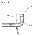
- the suction pipe 21 extending from the exterior of the closed casing 1 to the suction muffler 17 inside said casing 1 is folded in generally an L-shape, and includes a first passage 21a having its one end inserted through the hole 17d, into the upper chamber 17a of the suction muffler 17 so as to be positioned therein, a second passage 12b fixed to the lower casing 1b of the closed casing 1 and also folded generally in an L-shape so as to be positioned, at its one end, outside the closed casing 1, and a third passage 21c formed by closely winding a wire material in a coil shape for connecting said first passage 21a with said second passage 21b.
- At least the second passage 21b is formed by stainless steel having a heat conductivity lower than that of iron which is the material for the closed casing 1. It is to be noted here that the first passage 21a and the third passage 21c may be formed either of copper or stainless steel.
- the cooling medium gas returned from the suction pipe 21 is compressed by the piston 8 in the cylinder 9 through the suction muffler 17 so as to be further discharged outside via the discharge muffler 15.
- the hermetic compressor C1 of the present invention as described so far, owing to the construction that the second passage 21b of the suction pipe 21 contacting the closed casing 1 is made of stainless steel, the heat of the closed casing 1 is not readily conducted to said second passage 21b, and thus, the cooling medium gas is free from expansion by heating at this second passage 21b, whereby density lowering of the drawn-in cooling medium gas may be advantageously prevented.
Landscapes
- Engineering & Computer Science (AREA)
- Mechanical Engineering (AREA)
- General Engineering & Computer Science (AREA)
- Compressor (AREA)
Description
- The invention relates to a hermetic compressor comprising a closed casing, a compressing unit having a cylinder and a piston, an electric motor for reciprocating the piston, a suction muffler communicating with a suction port of said compressing unit, and a suction pipe including a first section inserted with its one end in said suction muffler, a second section fixed to said closed casing and leading to the outside of said closed casing and a flexible third section which connects said first section with said second section.
- It has been a recent trend to improve the compression of a reciprocating type cooling medium compressor in a cooling system such as a cold storage, freezing chamber or the like. As one technique for meeting such a requirement, it has been proposed to eliminate the disadvantage that a suction gas is heated and expanded in the compressor so that the suction gas with a low density is drawn into a cylinder for being compressed, whereby reduction in density of the suction gas is prevented for higher suction efficiency.
- From US-A-4,531,894 a hermetic compressor of the kind described above is known, in which a suction pipe including a flexible section is mounted with its one end to the suction muffler, and with its second end being fixed to the closed casing. In this arrangement, however, the suction pipe is generally made of copper, so that the suction is heated through heat exchange with respect to the casing of the compressor, with consequent heating of the suction gas. Therefore, only a poor improvement of the compression efficiency can be obtained.
- It is an object of the present invention to provide an improved hermetic compressor in which heating of the suction gas of the cooling medium compressor by the casing is avoided.
- According to the invention the hermetic compressor of the kind described above is characterized in that said second section is made of material having a heat conductivity which is lower than that of said closed casing. By such an arrangement, a hermetic compressor is provided which is superior in compression efficiency, with substantial elimination of disadvantages inherent in the conventional arrangements of this kind.
- Preferable embodiments are defined in the dependent claims.
- These and other objects and features of the present invention will become apparent from the following description taken in conjunction with the preferred embodiment thereof with reference to the accompanying drawings, in which;
- Fig. 1 is a side sectional view of a hermetic compressor according to one preferred embodiment of the present invention,
- Fig. 2 is a cross section taken along the line II-II in Fig. 1, and
- Fig. 3 is also a fragmentary cross section taken along the line III-III in Fig. 1.
- Before the description of the present invention proceeds, it is to be noted that like parts are designated by like reference numerals throughout the accompanying drawings.
- Referring now to the drawings, there is shown in Figs. 1 to 3, a hermetic compressor C1 according to a preferred embodiment of the present invention, which generally includes a closed
casing 1, acompressing unit 6 provided with acylinder block 10 having acylinder 9 formed with anopening 7 and accommodated in the closedcasing 1 and apiston 8 accommodated in thecylinder 9, anelectric motor 2 for reciprocating thepiston 8 of thecompressing unit 6, avalve plate 12 provided to cover theopening 7 of thecylinder 9 and provided with valves at a suction port and a discharge port thereof, a header provided for thevalve seat 12 at its side remote from thecylinder 9, asuction muffler 17 for leading a cooling medium to the suction port of thevalve plate 12, adischarge muffler 15 into which the cooling medium from the discharge port of thevalve plate 12 flows so as to be led to outside of the closedcasing 1, and asuction pipe 21 fixed to the closedcasing 1 for leading the suction gas to thesuction muffler 17. - More specifically, the closed
casing 1 made, for example, of iron is constituted by an upper casing 1a fitted over a peripheral edge of a lower casing 1b, with a junction therebetween being welded for combination. On the upper side of thecasing 1, there is provided theelectric motor 2 connected through wires W, with anelectric plug 3 provided in the lower casing 1b at the left side in Fig. 2, with acrank shaft 5 which extends vertically in Fig. 2 being mounted on arotor 4 of saidmotor 2. - The
compressing unit 6 located at the lower side of the closedcasing 1 includes thecylinder block 10 provided with thecylinder 9 having theopening 7 at its one side, and thepiston 8 movably accommodated therein. Saidpiston 8 is connected with saidcrank shaft 5 through a connecting rod 11 so as to transmit rotation of thecrank shaft 5 to thepiston 8 following the reciprocating movement thereof. On theopening 7 of thecylinder 9, thevalve plate 12 having the suction port, discharge port, and valves provided at both ports (not particularly shown), and acylinder head 13 are attached. As shown in Figs. 1 and 2, thiscylinder head 13 is fixed to thecylinder block 10 through thevalve plate 12 by setscrews 14. - The
discharge muffler 15 which once receives the flow of the compressed cooling medium gas discharged from said discharge port, and then, leads said gas out of the closedcasing 1 is fixed to thecylinder block 10 by ascrew 16. Thesuction muffler 17 arranged to guide the cooling medium into said suction port is made, for example, of a plastic material, and is divided into anupper chamber 17a and alower chamber 17b through apartition plate 19 formed with ahole 18 and provided therein, with thelower chamber 17b being arranged to lead the cooling medium to said suction port through a communicatingpipe 20, while theupper chamber 17a has ahole 17d formed in itsside wall 17c. Thesuction pipe 21 extending from the exterior of the closedcasing 1 to thesuction muffler 17 inside saidcasing 1 is folded in generally an L-shape, and includes afirst passage 21a having its one end inserted through thehole 17d, into theupper chamber 17a of thesuction muffler 17 so as to be positioned therein, a second passage 12b fixed to the lower casing 1b of the closedcasing 1 and also folded generally in an L-shape so as to be positioned, at its one end, outside the closedcasing 1, and athird passage 21c formed by closely winding a wire material in a coil shape for connecting saidfirst passage 21a with saidsecond passage 21b. In thesuction pipe 21 having the construction as described above, at least thesecond passage 21b is formed by stainless steel having a heat conductivity lower than that of iron which is the material for the closedcasing 1. It is to be noted here that thefirst passage 21a and thethird passage 21c may be formed either of copper or stainless steel. - In the above arrangement, the cooling medium gas returned from the
suction pipe 21 is compressed by thepiston 8 in thecylinder 9 through thesuction muffler 17 so as to be further discharged outside via thedischarge muffler 15. - It should be particularly noted here that according to the hermetic compressor C1 of the present invention as described so far, owing to the construction that the
second passage 21b of thesuction pipe 21 contacting the closedcasing 1 is made of stainless steel, the heat of the closedcasing 1 is not readily conducted to saidsecond passage 21b, and thus, the cooling medium gas is free from expansion by heating at thissecond passage 21b, whereby density lowering of the drawn-in cooling medium gas may be advantageously prevented.
Claims (3)
- A hermetic compressor comprising
a closed casing (1),
a compressing unit (6) having a cylinder (9) and a piston (8),
an electric motor (2) for reciprocating the piston (8),
a suction muffler (17) communicating with a suction port of said compressing unit (6), and
a suction pipe (21) including a first section (21a) inserted with its one end in said suction muffler (17), a second section (21b) fixed to said closed casing (1) and leading to the outside of said closed casing (1) and a flexible third section (21c) which connects said first section (21a) with said second section (21b);
characterized in that
said second section (21b) is made of material having a heat conductivity lower than that of said closed casing (1). - A hermetic compressor as claimed in claim 1,
wherein said third section (21c) is formed by a coil spring pipe. - A hermetic compressor as claimed in claim 1 or 2,
wherein said closed casing (1) is made of iron, said suction pipe (21, 23), or said second section (21b) being formed of stainless steel.
Priority Applications (7)
| Application Number | Priority Date | Filing Date | Title |
|---|---|---|---|
| DE68919845T DE68919845T2 (en) | 1989-08-04 | 1989-08-04 | Hermetic compressor. |
| EP93119090A EP0588381B1 (en) | 1989-08-04 | 1989-08-04 | Hermetic compressor |
| DE68926823T DE68926823T2 (en) | 1989-08-04 | 1989-08-04 | Hermetic compressor |
| EP89114443A EP0411195B1 (en) | 1989-08-04 | 1989-08-04 | Hermetic compressor |
| ES93119090T ES2092210T3 (en) | 1989-08-04 | 1989-08-04 | HERMETIC COMPRESSOR. |
| ES89114443T ES2067505T3 (en) | 1989-08-04 | 1989-08-04 | HERMETIC COMPRESSOR. |
| US07/390,816 US4990067A (en) | 1989-08-04 | 1989-08-07 | Hermetic compressor |
Applications Claiming Priority (1)
| Application Number | Priority Date | Filing Date | Title |
|---|---|---|---|
| EP89114443A EP0411195B1 (en) | 1989-08-04 | 1989-08-04 | Hermetic compressor |
Related Child Applications (2)
| Application Number | Title | Priority Date | Filing Date |
|---|---|---|---|
| EP93119090A Division EP0588381B1 (en) | 1989-08-04 | 1989-08-04 | Hermetic compressor |
| EP93119090.4 Division-Into | 1989-08-04 |
Publications (2)
| Publication Number | Publication Date |
|---|---|
| EP0411195A1 EP0411195A1 (en) | 1991-02-06 |
| EP0411195B1 true EP0411195B1 (en) | 1994-12-07 |
Family
ID=8201719
Family Applications (2)
| Application Number | Title | Priority Date | Filing Date |
|---|---|---|---|
| EP93119090A Expired - Lifetime EP0588381B1 (en) | 1989-08-04 | 1989-08-04 | Hermetic compressor |
| EP89114443A Expired - Lifetime EP0411195B1 (en) | 1989-08-04 | 1989-08-04 | Hermetic compressor |
Family Applications Before (1)
| Application Number | Title | Priority Date | Filing Date |
|---|---|---|---|
| EP93119090A Expired - Lifetime EP0588381B1 (en) | 1989-08-04 | 1989-08-04 | Hermetic compressor |
Country Status (4)
| Country | Link |
|---|---|
| US (1) | US4990067A (en) |
| EP (2) | EP0588381B1 (en) |
| DE (2) | DE68919845T2 (en) |
| ES (2) | ES2067505T3 (en) |
Families Citing this family (21)
| Publication number | Priority date | Publication date | Assignee | Title |
|---|---|---|---|---|
| JPH03258980A (en) * | 1990-03-06 | 1991-11-19 | Matsushita Refrig Co Ltd | Sealed type electric compressor |
| JPH03281991A (en) * | 1990-03-30 | 1991-12-12 | Toshiba Corp | Coolant compressor |
| KR940003845Y1 (en) * | 1991-12-28 | 1994-06-15 | 주식회사 금성사 | Compressor |
| KR200141490Y1 (en) * | 1993-04-24 | 1999-05-15 | 김광호 | Noise attenuation device of the compressor |
| US5496156A (en) * | 1994-09-22 | 1996-03-05 | Tecumseh Products Company | Suction muffler |
| US5804777A (en) * | 1995-11-02 | 1998-09-08 | Lg Electronics Inc. | Suction noise muffler for hermetic compressor |
| BR9601662A (en) * | 1996-05-10 | 1998-03-31 | Brasil Compressores Sa | Suction arrangement for hermetic reciprocating compressor |
| KR100254486B1 (en) * | 1996-10-23 | 2000-05-01 | 가나이 쓰도무 | Silencer for Hermetic Compressor and Hermetic Compressor with it |
| KR100197712B1 (en) * | 1996-11-19 | 1999-06-15 | 윤종용 | Flow prevention device of hermetic compressor |
| JPH10318140A (en) * | 1997-05-21 | 1998-12-02 | Matsushita Refrig Co Ltd | Hermetic motor-driven compressor |
| DE19881579D2 (en) * | 1997-08-29 | 2000-10-12 | Luk Fahrzeug Hydraulik | Kompressor mit überlastenkopplungseinrichtung |
| CN1161543C (en) * | 2000-11-10 | 2004-08-11 | 三星光州电子株式会社 | Booster for hermetic compressors |
| FR2824383B1 (en) * | 2001-05-04 | 2007-05-11 | Mecaplast Sa | DEVICE FOR ATTENUATING THE SOUND LEVEL OF A GASEOUS FLUID CIRCUIT |
| CN100396918C (en) * | 2003-06-26 | 2008-06-25 | 乐金电子(天津)电器有限公司 | Discharge silencer fixing structure of hermetic compressor |
| JP4701789B2 (en) * | 2005-03-30 | 2011-06-15 | パナソニック株式会社 | Hermetic compressor |
| KR100932255B1 (en) * | 2005-08-04 | 2009-12-16 | 아세릭 에이. 에스 | compressor |
| SI2300716T1 (en) * | 2008-05-01 | 2015-12-31 | Arcelik Anonim Sirketi | A compressor |
| WO2011154474A1 (en) * | 2010-06-09 | 2011-12-15 | Arcelik Anonim Sirketi | A hermetic compressor |
| CN105332889A (en) * | 2015-10-26 | 2016-02-17 | 无锡市圣科不锈钢气动自控阀门厂 | Reciprocating compressor |
| CN106014920A (en) * | 2016-06-29 | 2016-10-12 | 安徽美芝制冷设备有限公司 | Compressor, assembly method for compressor and refrigerator |
| TR2022019044A1 (en) * | 2022-12-12 | 2024-06-21 | Arcelik As | ONE COMPRESSOR |
Family Cites Families (19)
| Publication number | Priority date | Publication date | Assignee | Title |
|---|---|---|---|---|
| US3871800A (en) * | 1974-03-11 | 1975-03-18 | Gen Electric | Hermetically sealed compressor suction tube assembly |
| JPS528506A (en) * | 1975-07-09 | 1977-01-22 | Hitachi Ltd | All closed motor driven compressor |
| US4240774A (en) * | 1979-02-15 | 1980-12-23 | General Electric Company | Hermetically sealed compressor suction tube and method of assembly |
| JPS5669478A (en) * | 1979-11-09 | 1981-06-10 | Hitachi Ltd | Closed-type motor compressor |
| US4313715A (en) * | 1979-12-21 | 1982-02-02 | Tecumseh Products Company | Anti-slug suction muffler for hermetic refrigeration compressor |
| US4370104A (en) * | 1980-07-22 | 1983-01-25 | White Consolidated Industries, Inc. | Suction muffler for refrigeration compressor |
| US4401418B1 (en) * | 1981-04-29 | 1998-01-06 | White Consolidated Ind Inc | Muffler system for refrigeration compressor |
| CA1210741A (en) * | 1981-08-25 | 1986-09-02 | Hideki Kawai | Sealed type motor compressor |
| DE3213476C1 (en) * | 1982-04-10 | 1983-06-01 | Danfoss A/S, 6430 Nordborg | Refrigeration machine with encapsulated motor compressor |
| FR2532731B3 (en) * | 1982-09-02 | 1985-07-19 | Sanyo Electric Co | HERMETIC MOTOR COMPRESSOR GROUP |
| DE3332259A1 (en) * | 1983-09-07 | 1985-03-28 | Danfoss A/S, Nordborg | REFRIGERATOR COMPRESSORS |
| IT1172782B (en) * | 1983-12-12 | 1987-06-18 | Necchi Spa | SILENCER FOR MOTOR-COMPRESSORS |
| US4549857A (en) * | 1984-08-03 | 1985-10-29 | Carrier Corporation | Hermetic motor compressor having a suction inlet and seal |
| IT1184167B (en) * | 1985-03-21 | 1987-10-22 | Eurodomestici Ind Riunite | IMPROVEMENT IN SEALED MOTOR-COMPRESSORS FOR REFRIGERANT CIRCUITS |
| DE3604830A1 (en) * | 1986-02-15 | 1987-08-20 | Danfoss As | Method of fastening a tube to the wall and an electrode for carrying out this method |
| BR8602173A (en) * | 1986-05-02 | 1987-12-22 | Brasil Compressores Sa | IMPROVEMENT IN A HERMETIC COOLING COMPRESSOR SUCTION SYSTEM |
| DE3622996A1 (en) * | 1986-07-09 | 1988-02-18 | Danfoss As | SUCTION MUFFLER |
| US4784581A (en) * | 1987-01-12 | 1988-11-15 | White Consolidated Industries, Inc. | Compressor head and suction muffler for hermetic compressor |
| US4844705A (en) * | 1988-01-25 | 1989-07-04 | Tecumseh Products Company | Suction line adaptor and filter for a hermetic compressor |
-
1989
- 1989-08-04 EP EP93119090A patent/EP0588381B1/en not_active Expired - Lifetime
- 1989-08-04 EP EP89114443A patent/EP0411195B1/en not_active Expired - Lifetime
- 1989-08-04 ES ES89114443T patent/ES2067505T3/en not_active Expired - Lifetime
- 1989-08-04 DE DE68919845T patent/DE68919845T2/en not_active Expired - Fee Related
- 1989-08-04 ES ES93119090T patent/ES2092210T3/en not_active Expired - Lifetime
- 1989-08-04 DE DE68926823T patent/DE68926823T2/en not_active Expired - Fee Related
- 1989-08-07 US US07/390,816 patent/US4990067A/en not_active Expired - Fee Related
Also Published As
| Publication number | Publication date |
|---|---|
| ES2092210T3 (en) | 1996-11-16 |
| US4990067A (en) | 1991-02-05 |
| DE68926823D1 (en) | 1996-08-14 |
| DE68919845T2 (en) | 1995-07-13 |
| EP0588381A2 (en) | 1994-03-23 |
| EP0411195A1 (en) | 1991-02-06 |
| ES2067505T3 (en) | 1995-04-01 |
| EP0588381A3 (en) | 1994-04-06 |
| EP0588381B1 (en) | 1996-07-10 |
| DE68926823T2 (en) | 1996-11-07 |
| DE68919845D1 (en) | 1995-01-19 |
Similar Documents
| Publication | Publication Date | Title |
|---|---|---|
| EP0588381B1 (en) | Hermetic compressor | |
| US4911619A (en) | Suction system of hermetic refrigeration compressor | |
| CA1264466A (en) | Refrigerator compressor | |
| US4573880A (en) | Hermetically sealed motor compressor | |
| US4784581A (en) | Compressor head and suction muffler for hermetic compressor | |
| US5288212A (en) | Cylinder head of hermetic reciprocating compressor | |
| US5304044A (en) | Hermetic compressor | |
| US5722818A (en) | Suction valve arrangement for a hermetic compressor | |
| US7004735B2 (en) | Scroll-type fluid machine having a path to pass and cool the fluid | |
| EP1446580B1 (en) | Suction muffler for a reciprocating hermetic compressor | |
| KR0143182B1 (en) | compressor | |
| US4569645A (en) | Rotary compressor with heat exchanger | |
| US5451727A (en) | Noise suppressing apparatus for hermetic reciprocating compressor | |
| US8257061B2 (en) | Hermetic compressor with internal thermal insulation | |
| CN86102710A (en) | Hermetic motor-compressor units for refrigeration circuits | |
| CA2069208C (en) | Refrigeration compressor having a contoured piston | |
| US4623304A (en) | Hermetically sealed rotary compressor | |
| US20020005270A1 (en) | Refrigerator and method for manufacturing heat pipe unit of refrigerator | |
| JP4701789B2 (en) | Hermetic compressor | |
| US4396359A (en) | Motor compressor unit | |
| USRE33902E (en) | Compressor head and suction muffler for hermetic compressor | |
| CN114508475A (en) | Interior exhaust structure, compressor and attemperator | |
| US4930406A (en) | Refrigerant gas compressor construction | |
| JPS5852394Y2 (en) | hermetic compressor | |
| EP0105127A1 (en) | Rotary compressor |
Legal Events
| Date | Code | Title | Description |
|---|---|---|---|
| PUAI | Public reference made under article 153(3) epc to a published international application that has entered the european phase |
Free format text: ORIGINAL CODE: 0009012 |
|
| 17P | Request for examination filed |
Effective date: 19890804 |
|
| AK | Designated contracting states |
Kind code of ref document: A1 Designated state(s): DE ES FR GB IT SE |
|
| 17Q | First examination report despatched |
Effective date: 19920610 |
|
| GRAA | (expected) grant |
Free format text: ORIGINAL CODE: 0009210 |
|
| AK | Designated contracting states |
Kind code of ref document: B1 Designated state(s): DE ES FR GB IT SE |
|
| ITF | It: translation for a ep patent filed | ||
| REF | Corresponds to: |
Ref document number: 68919845 Country of ref document: DE Date of ref document: 19950119 |
|
| EAL | Se: european patent in force in sweden |
Ref document number: 89114443.8 |
|
| ET | Fr: translation filed | ||
| REG | Reference to a national code |
Ref country code: ES Ref legal event code: FG2A Ref document number: 2067505 Country of ref document: ES Kind code of ref document: T3 |
|
| PLBE | No opposition filed within time limit |
Free format text: ORIGINAL CODE: 0009261 |
|
| STAA | Information on the status of an ep patent application or granted ep patent |
Free format text: STATUS: NO OPPOSITION FILED WITHIN TIME LIMIT |
|
| 26N | No opposition filed | ||
| PGFP | Annual fee paid to national office [announced via postgrant information from national office to epo] |
Ref country code: DE Payment date: 20010730 Year of fee payment: 13 |
|
| PGFP | Annual fee paid to national office [announced via postgrant information from national office to epo] |
Ref country code: GB Payment date: 20010801 Year of fee payment: 13 |
|
| PGFP | Annual fee paid to national office [announced via postgrant information from national office to epo] |
Ref country code: SE Payment date: 20010807 Year of fee payment: 13 |
|
| PGFP | Annual fee paid to national office [announced via postgrant information from national office to epo] |
Ref country code: FR Payment date: 20010810 Year of fee payment: 13 |
|
| PGFP | Annual fee paid to national office [announced via postgrant information from national office to epo] |
Ref country code: ES Payment date: 20010824 Year of fee payment: 13 |
|
| REG | Reference to a national code |
Ref country code: GB Ref legal event code: IF02 |
|
| PG25 | Lapsed in a contracting state [announced via postgrant information from national office to epo] |
Ref country code: GB Free format text: LAPSE BECAUSE OF NON-PAYMENT OF DUE FEES Effective date: 20020804 |
|
| PG25 | Lapsed in a contracting state [announced via postgrant information from national office to epo] |
Ref country code: SE Free format text: LAPSE BECAUSE OF NON-PAYMENT OF DUE FEES Effective date: 20020805 Ref country code: ES Free format text: LAPSE BECAUSE OF NON-PAYMENT OF DUE FEES Effective date: 20020805 |
|
| PG25 | Lapsed in a contracting state [announced via postgrant information from national office to epo] |
Ref country code: DE Free format text: LAPSE BECAUSE OF NON-PAYMENT OF DUE FEES Effective date: 20030301 |
|
| GBPC | Gb: european patent ceased through non-payment of renewal fee |
Effective date: 20020804 |
|
| EUG | Se: european patent has lapsed | ||
| PG25 | Lapsed in a contracting state [announced via postgrant information from national office to epo] |
Ref country code: FR Free format text: LAPSE BECAUSE OF NON-PAYMENT OF DUE FEES Effective date: 20030430 |
|
| REG | Reference to a national code |
Ref country code: FR Ref legal event code: ST |
|
| REG | Reference to a national code |
Ref country code: ES Ref legal event code: FD2A Effective date: 20030912 |
|
| PG25 | Lapsed in a contracting state [announced via postgrant information from national office to epo] |
Ref country code: IT Free format text: LAPSE BECAUSE OF NON-PAYMENT OF DUE FEES;WARNING: LAPSES OF ITALIAN PATENTS WITH EFFECTIVE DATE BEFORE 2007 MAY HAVE OCCURRED AT ANY TIME BEFORE 2007. THE CORRECT EFFECTIVE DATE MAY BE DIFFERENT FROM THE ONE RECORDED. Effective date: 20050804 |