EP0410836A1 - Device for an edge-trimming machine removing a burr along the edge of a workpiece - Google Patents
Device for an edge-trimming machine removing a burr along the edge of a workpiece Download PDFInfo
- Publication number
- EP0410836A1 EP0410836A1 EP90401989A EP90401989A EP0410836A1 EP 0410836 A1 EP0410836 A1 EP 0410836A1 EP 90401989 A EP90401989 A EP 90401989A EP 90401989 A EP90401989 A EP 90401989A EP 0410836 A1 EP0410836 A1 EP 0410836A1
- Authority
- EP
- European Patent Office
- Prior art keywords
- tool
- contour
- burr
- edge
- cutter
- Prior art date
- Legal status (The legal status is an assumption and is not a legal conclusion. Google has not performed a legal analysis and makes no representation as to the accuracy of the status listed.)
- Granted
Links
Images

Classifications
-
- B—PERFORMING OPERATIONS; TRANSPORTING
- B23—MACHINE TOOLS; METAL-WORKING NOT OTHERWISE PROVIDED FOR
- B23Q—DETAILS, COMPONENTS, OR ACCESSORIES FOR MACHINE TOOLS, e.g. ARRANGEMENTS FOR COPYING OR CONTROLLING; MACHINE TOOLS IN GENERAL CHARACTERISED BY THE CONSTRUCTION OF PARTICULAR DETAILS OR COMPONENTS; COMBINATIONS OR ASSOCIATIONS OF METAL-WORKING MACHINES, NOT DIRECTED TO A PARTICULAR RESULT
- B23Q11/00—Accessories fitted to machine tools for keeping tools or parts of the machine in good working condition or for cooling work; Safety devices specially combined with or arranged in, or specially adapted for use in connection with, machine tools
- B23Q11/04—Arrangements preventing overload of tools, e.g. restricting load
-
- B—PERFORMING OPERATIONS; TRANSPORTING
- B23—MACHINE TOOLS; METAL-WORKING NOT OTHERWISE PROVIDED FOR
- B23C—MILLING
- B23C3/00—Milling particular work; Special milling operations; Machines therefor
- B23C3/12—Trimming or finishing edges, e.g. deburring welded corners
-
- Y—GENERAL TAGGING OF NEW TECHNOLOGICAL DEVELOPMENTS; GENERAL TAGGING OF CROSS-SECTIONAL TECHNOLOGIES SPANNING OVER SEVERAL SECTIONS OF THE IPC; TECHNICAL SUBJECTS COVERED BY FORMER USPC CROSS-REFERENCE ART COLLECTIONS [XRACs] AND DIGESTS
- Y10—TECHNICAL SUBJECTS COVERED BY FORMER USPC
- Y10T—TECHNICAL SUBJECTS COVERED BY FORMER US CLASSIFICATION
- Y10T29/00—Metal working
- Y10T29/51—Plural diverse manufacturing apparatus including means for metal shaping or assembling
- Y10T29/5182—Flash remover
-
- Y—GENERAL TAGGING OF NEW TECHNOLOGICAL DEVELOPMENTS; GENERAL TAGGING OF CROSS-SECTIONAL TECHNOLOGIES SPANNING OVER SEVERAL SECTIONS OF THE IPC; TECHNICAL SUBJECTS COVERED BY FORMER USPC CROSS-REFERENCE ART COLLECTIONS [XRACs] AND DIGESTS
- Y10—TECHNICAL SUBJECTS COVERED BY FORMER USPC
- Y10T—TECHNICAL SUBJECTS COVERED BY FORMER US CLASSIFICATION
- Y10T409/00—Gear cutting, milling, or planing
- Y10T409/30—Milling
- Y10T409/3042—Means to remove scale or raised surface imperfection
- Y10T409/304256—Means to remove flash or burr
-
- Y—GENERAL TAGGING OF NEW TECHNOLOGICAL DEVELOPMENTS; GENERAL TAGGING OF CROSS-SECTIONAL TECHNOLOGIES SPANNING OVER SEVERAL SECTIONS OF THE IPC; TECHNICAL SUBJECTS COVERED BY FORMER USPC CROSS-REFERENCE ART COLLECTIONS [XRACs] AND DIGESTS
- Y10—TECHNICAL SUBJECTS COVERED BY FORMER USPC
- Y10T—TECHNICAL SUBJECTS COVERED BY FORMER US CLASSIFICATION
- Y10T409/00—Gear cutting, milling, or planing
- Y10T409/30—Milling
- Y10T409/306664—Milling including means to infeed rotary cutter toward work
- Y10T409/307224—Milling including means to infeed rotary cutter toward work with infeed control means energized in response to activator stimulated by condition sensor
- Y10T409/307336—In response to work condition
Definitions
- the invention relates to a device for bypassing blocking burrs for a deburring tool.
- burrs produced for example on the foundry pieces at the location of the joint plane have an unpredictable size and which can vary greatly along the contour to be deburred.
- blocking burrs which are capable of stopping the tool and damaging it.
- Systems are simply known where an unacceptable machining condition is detected, in particular by raising the level of vibrations, in order to then withdraw the tool and stop the machining.
- the system usually present on the wrists of robots carrying a deburring tool which consists of an elastic element which allows the tool to approach or move away from the contour depending on the cutting forces, is not enough because it is impossible to guarantee that the tool will be released sufficiently.
- the device which is the subject of the invention ensures the circumvention of burrs whatever their dimensions and regardless of the characteristics of the robot and the cutting tool.
- the invention consists of a device for bypassing blocking burrs for a rotary deburring tool dependent on a support, comprising means for pressing the tool on the contour to be deburred and for retracting the tool at the above the contour to be deburred arranged between the tool and the support, a sensor measuring a quantity representative of the speed of rotation of the tool, as well as a control circuit controlling the pressing and retraction means according to the values taken by said quantity.
- the pressing and retraction means is a pneumatic cylinder having a chamber, the volume increases of which correspond to displacements of the tool towards the contour to be deburred, connected by the servo circuit either to a source of gas at constant pressure. either to a deflation opening.
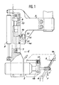
- FIG. 1 represents a milling cutter 1 at the end of a spindle 2 actuated by a pneumatic motor and connected to a robot wrist 3. The latter is moved at a uniform feed speed so that milling cutter 1 molds a contour 4 by removing a burr located on this contour. A blocking portion of the burr is referenced by 5.
- the axis of rotation of the cutter 1 is approximately perpendicular to the contour 4, and the cutting forces include a tool pressing component F perpendicular to the axis of rotation of the cutter 1, normal to the contour 4 and oriented , in the case of downstream milling, in the opposite direction to the wrist 3.
- This pressing force is obtained by means of a pneumatic cylinder 6 whose rod 7, fixed to the spindle 2, is parallel to the pressing component F and whose cylinder 8 is fixed at one end to the wrist 3.
- a damper 9 is also arranged between the spindle 2 and the wrist 3 in parallel with the pneumatic cylinder 8.
- an electrical contact 10 is attached to the wrist 3 near the cylinder 8 and comprises, at the end of an elastic blade 12, a sensitive element 11 which is placed in front of or in a longitudinal groove 14 bounded by one end 15 and established on the slide part 13 secured to spindle 2.
- a tachometer 17 is arranged on the spindle 2, opposite a disc 18 rotating with the cutter 1.
- the air stream 23 therefore enters the housing 24 and deforms the membrane 26 which touches the pair of contacts 27 and 28 and thus closes, since it is made of conductive material, an electrical detection circuit not shown in detail.
- the overpressure in the housing 24 ceases, the membrane 26 straightens and the electrical circuit opens.
- the great advantage of the pneumatic sensor 19 is that it is very reliable and in particular insensitive to various dust and dirt, which the air current immediately sweeps but which could cover the transmission and reception parts of a sensor comprising a light ray. .
- the cylinder 8 contains two chambers 35 and 36 separated by a piston 37 linked to the rod 7.
- the first chamber 35 whose increase in volume corresponds to a displacement of the cutter 1 towards the contour 4 is connected either to a pressure source P1 by means of a manual pressure regulator and pressure gauge device 39, or to a calibrated deflation orifice 40.
- a solenoid valve 41 ensures the switching.
- the second chamber 36 is connected by a solenoid valve 42 or to a second pressure source P2 by means of an adjustment device with manual pressure regulator and pressure gauge 43, or at a deflation opening 44.
- the control of the solenoid valves 41 and 42 is ensured by the tachometer 17 by means of computer means consisting either of software for controlling the robot wrist 3 or of an autonomous electronic card.
- the increase in the size of the machined burr results in a slowing down of the rotation of the cutter 1.
- the tachometer finds that the speed of rotation becomes less than a threshold value, we consider that we are facing 'a blocking burr 5 and the solenoid valves 41 and 42 are switched simultaneously so that the pressure P2 enters the second chamber 36 while the first chamber 35 is connected to the deflation orifice 40: the rod 7 is pulled into the cylinder 8, and the cutter 1 retracted and away from the contour 4.
- the pneumatic sensor 19 is useful for completing the measurements of the tachometer 17 in the case of burrs of very large size: it is then to be feared that the retraction of the cutter 1 is not fast enough because of the reaction times of the servo-control.
- the pneumatic sensor 19 makes it possible to anticipate these burrs and to initiate the disengagement of the cutter 1 in advance.
- the pneumatic sensor 19 can be used to predict the arrival on the blocking burrs 5 and to slow down the advance of the wrist 3.
- the speed of rotation corresponding to the retraction threshold is set by the user but is advantageously chosen according to the wear of the cutter 1 and can be approached by a linear relationship between that corresponding to a new cutter and that corresponding to a cutter to be resharpened.
Abstract
Description
L'invention se rapporte à un dispositif de contournement de bavures bloquantes pour un outil d'ébavurage.The invention relates to a device for bypassing blocking burrs for a deburring tool.
Les bavures produites par exemple sur les pièces de fonderie à l'emplacement du plan de joint ont une taille imprévisible et qui peut varier fortement le long du contour à ébavurer. Il n'existe pas dans le cas d'usinages robotisés de moyen pour prévoir l'arrivée de l'outil sur des parties de grande taille dites "bavures bloquantes" qui sont susceptibles d'arrêter l'outil et de l'endommager. On connaît simplement des systèmes où une condition inacceptable d'usinage est détectée, notamment par l'élévation du niveau des vibrations, afin de retirer alors l'outil et d'arrêter l'usinage.The burrs produced for example on the foundry pieces at the location of the joint plane have an unpredictable size and which can vary greatly along the contour to be deburred. In the case of robotic machining, there is no means for predicting the arrival of the tool on large parts known as "blocking burrs" which are capable of stopping the tool and damaging it. Systems are simply known where an unacceptable machining condition is detected, in particular by raising the level of vibrations, in order to then withdraw the tool and stop the machining.
Le système habituellement présent sur les poignets de robots porteurs d'un outil d'ébavurage, qui consiste en un élément élastique qui permet à l'outil de se rapprocher ou de s'éloigner du contour en fonction des efforts de coupe, ne suffit pas car il est impossible de garantir que l'outil sera dégagé suffisamment.The system usually present on the wrists of robots carrying a deburring tool, which consists of an elastic element which allows the tool to approach or move away from the contour depending on the cutting forces, is not enough because it is impossible to guarantee that the tool will be released sufficiently.
Le dispositif objet de l'invention assure le contournement des bavures quelles que soient leurs dimensions et indépendamment des caractéristiques du robot et de l'outil de coupe.The device which is the subject of the invention ensures the circumvention of burrs whatever their dimensions and regardless of the characteristics of the robot and the cutting tool.
Il consiste à appliquer à l'outil un effort de coupe normalement constant sur le contour et à effectuer un dégagement momentané de l'outil dès que la quantité de matière à enlever devient excessive, ce qui peut être repéré à l'aide des paramètres de coupe et notamment de la vitesse de rotation de l'outil. Dans le cas d'un moteur pneumatique, on mesurera directement cette vitesse par un tachymètre et la rétraction de l'outil sera commandée dès qu'une vitesse de seuil sera atteinte. Dans le cas d'un moteur électrique, on obtiendra éventuellement une information équivalente en mesurant le courant consommé, qui peut être facilement relié à la vitesse de rotation de l'outil.It consists in applying to the tool a normally constant cutting force on the contour and in carrying out a temporary release of the tool as soon as the quantity of material to be removed becomes excessive, which can be identified using the parameters of cutting and in particular the speed of rotation of the tool. In the case of an air motor, this speed will be measured directly by a tachometer and the retraction of the tool will be controlled as soon as a threshold speed is reached. In the case of an electric motor, equivalent information may be obtained by measuring the current consumed, which can be easily linked to the speed of rotation of the tool.
Plus précisément, l'invention consiste en un dispositif de contournement de bavures bloquantes pour un outil d'ébavurage rotatif dépendant d'un support, comprenant un moyen de pressage de l'outil sur le contour à ébavurer et de rétraction de l'outil au-dessus du contour à ébavurer disposé entre l'outil et le support, un capteur mesurant une grandeur représentative de la vitesse de rotation de l'outil, ainsi qu'un circuit d'asservissement commandant le moyen de pressage et de rétraction en fonction des valeurs prises par ladite grandeur.More specifically, the invention consists of a device for bypassing blocking burrs for a rotary deburring tool dependent on a support, comprising means for pressing the tool on the contour to be deburred and for retracting the tool at the above the contour to be deburred arranged between the tool and the support, a sensor measuring a quantity representative of the speed of rotation of the tool, as well as a control circuit controlling the pressing and retraction means according to the values taken by said quantity.
Le moyen de pressage et de rétraction est un vérin pneumatique ayant une chambre, dont les accroissements de volume correspondent à des déplacements de l'outil vers le contour à ébavurer, reliée par le circuit d'asservissement soit à une source de gaz à pression constante soit à un orifice de dégonflage.The pressing and retraction means is a pneumatic cylinder having a chamber, the volume increases of which correspond to displacements of the tool towards the contour to be deburred, connected by the servo circuit either to a source of gas at constant pressure. either to a deflation opening.
On va maintenant décrire l'invention à l'aide des figures suivantes annexées à titre illustratif et non limitatif :
- - la figure 1 représente une réalisation de l'invention ;
- - la figure 2 représente un élément optionnel de l'invention ; et
- - la figure 3 représente plus précisément les asservissements utilisés.
- - Figure 1 shows an embodiment of the invention;
- - Figure 2 shows an optional element of the invention; and
- - Figure 3 shows more precisely the controls used.
La figure 1 représente une fraise 1 à l'extrémité d'une broche 2 actionnée par un moteur pneumatique et reliée à un poignet de robot 3. Ce dernier est déplacé à une vitesse d'avance uniforme de sorte que la fraise 1 usine un contour 4 en retirant une bavure située sur ce contour. On a référencé par 5 une portion bloquante de la bavure. L'axe de rotation de la fraise 1 est à peu près perpendiculaire au contour 4, et les efforts de coupe comprennent une composante de pressage d'outil F perpendiculaire à l'axe de rotation de la fraise 1, normale au contour 4 et orientée, dans le cas d'un fraisage en avalant, en direction opposée au poignet 3.FIG. 1 represents a
Cet effort de pressage est obtenu grâce à un vérin pneumatique 6 dont la tige 7, fixée à la broche 2, est parallèle à la composante de pressage F et dont le cylindre 8 est fixé à une extrémité au poignet 3. Une glissière verticale 13, parallèle à l'effort de pressage F, guide la broche en permettant sa translation par rapport au poignet 3. Un amortisseur 9 est également disposé entre la broche 2 et le poignet 3 en parallèle avec le vérin pneumatique 8. Enfin, un contact électrique 10 est fixé au poignet 3 à proximité du cylindre 8 et comprend, à l'extrémité d'une lame élastique 12, un élément sensible 11 qui est placé devant ou dans une rainure longitudinale 14 limitée par une extrémité 15 et établie sur la partie de glissière 13 solidaire de la broche 2.This pressing force is obtained by means of a
Un tachymètre 17 est disposé sur la broche 2, en face d'un disque 18 tournant avec la fraise 1. On peut facultativement prévoir un capteur pneumatique 19 qui précède la fraise 1 le long du contour 4 sans toucher celui-ci et qui se compose, comme on le voit figure 2, de deux parties séparées dont l'une est constituée d'un tube 20 terminé par une partie recourbée 21 et d'une source d'air comprimé 22 qui entretient un courant d'air 23 dans le tube 20, puis hors de celui-ci en direction de l'autre partie du capteur pneumatique 19 ; cette autre partie est constituée d'un boîtier 24 muni d'un orifice 25 devant le courant d'air 23 et qui comprend à l'intérieur une membrane déformable 26 séparant de l'orifice 25 une paire de contacts électriques séparés 27 et 28.A
En fonctionnement normal, le courant d'air 23 pénètre donc dans le boîtier 24 et déforme la membrane 26 qui touche la paire de contacts 27 et 28 et ferme ainsi, puisqu'elle est en matériau conducteur, un circuit électrique de détection non représenté en détail. Cependant, dès qu'une bavure bloquante 5 apparaît, elle s'interpose le long du courant d'air 23 : la surpression dans le boîtier 24 cesse, la membrane 26 se redresse et le circuit électrique s'ouvre. Le grand avantage du capteur pneumatique 19 est d'être très fiable et notamment insensible aux poussières et saletés diverses, que le courant d'air balaie immédiatement mais qui pourraient recouvrir les parties d'émission et de réception d'un capteur comportant un rayon lumineux.In normal operation, the
On se reporte maintenant également à la figure 3. Le cylindre 8 renferme deux chambres 35 et 36 séparées par un piston 37 lié à la tige 7. La première chambre 35, dont l'accroissement de volume correspond à un déplacement de la fraise 1 vers le contour 4, est reliée soit à une source de pression P1 par l'intermédiaire d'un dispositif à détendeur manuel et manomètre 39, soit à un orifice de dégonflage calibré 40. Une électrovanne 41 assure la commutation. De même, la seconde chambre 36 est reliée par une électrovanne 42 soit à une seconde source de pression P2 par l'intermédiaire d'un dispositif de réglage à détendeur manuel et manomètre 43, soit à un orifice de dégonflage 44.Reference is now also made to FIG. 3. The
La commande des électrovannes 41 et 42 est assurée par le tachymètre 17 par l'intermédiaire de moyens informatiques constitués soit d'un logiciel de pilotage du poignet de robot 3 soit d'une carte électronique autonome. L'accroissement de la taille de la bavure usinée se traduit par un ralentissement de la rotation de la fraise 1. Lorsque le tachymètre constate que la vitesse de rotation devient inférieure à une valeur de seuil, on considère qu'on se trouve en face d'une bavure bloquante 5 et les électrovannes 41 et 42 sont commutées simultanément de sorte que la pression P2 entre dans la seconde chambre 36 alors que la première chambre 35 est reliée à l'orifice de dégonflage 40 : la tige 7 est tirée dans le cylindre 8, et la fraise 1 rétractée et éloignée du contour 4. Dès que la vitesse de rotation redevient supérieure à la vitesse de seuil, une commutation inverse des électrovannes 41 et 42 relie la première chambre 35 à la source de pression P1, tout en reliant la seconde chambre 36 à l'orifice de dégonflage 44, et permet d'exercer à nouveau un effort de pressage F. Le capteur pneumatique 19 est utile pour compléter les mesures du tachymètre 17 dans le cas de bavures de très grande taille : il est alors à craindre que la rétraction de la fraise 1 ne soit pas suffisamment rapide à cause des temps de réaction de l'asservissement. Le capteur pneumatique 19 permet d'anticiper ces bavures et d'amorçer à l'avance le dégagement de la fraise 1.The control of the
Quand la fraise 1 parcourt le début d'une bavure bloquante 5, elle est donc progressivement rétractée par une suite de commutations. Comme le mouvement oscillatoire ainsi produit peut être très rapide, on utilise l'amortisseur 9 pour l'atténuer et rendre les commutations moins fréquentes. L'amortisseur 9, constitué en fait d'un verin dont le cylindre est relié au robot 3, la tige à la broche 2, et dont les chambres sont reliées entre elles par une dérivation à passage resserré 45, permet ainsi de limiter les broutements. L'utilisation d'un amortisseur réglable permet de fixer la vitesse de dégagement de la fraise, donnée par la formule V = F/B (F = effort de pressage, B = coefficient d'amortissement).When the
L'absence de bavure est repérée quand la fraise 1 tourne à une seconde vitesse de seuil correspondant à un usinage à vide. Cette seconde vitesse de seuil, évidemment supérieure à celle à laquelle les électrovannes 41 et 42 sont commutées, indique les endroits du contour 4 où l'ébavurage a été terminé. D'autres passes d'ébavurage sont par contre effectuées pour le reste du contour 4.The absence of burr is identified when the
Le contact 10 permet d'éviter des erreurs d'interprétation. En effet, à la fin d'une bavure, l'amortisseur 9 ne permet qu'un retour progressif de la fraise 1 vers le contour 4, et celle-ci peut être momentanément décollée de la fin de la bavure le long du contour 4 si le poignet 3 est avancé trop rapidement le long du contour 4. La fraise 1 tourne alors à vide et le système de pilotage pourrait en déduire à tort qu'il n'y a pas de bavure à cet endroit. C'est pourquoi le poignet 3 est déplacé à une distance constante du contour 4 -abstraction faite des bavures- pour que, dès qu'une bavure est rencontrée et que la fraise 1 doit être rétractée, même d'une petite quantité, l'élément sensible 11 dépasse l'extrémité 15 et plonge dans la rainure 14, ce qui indique plus sûrement au système de pilotage que l'ébavurage n'est pas terminé à cet endroit. Le capteur pneumatique 19 peut être utilisé pour prévoir l'arrivée sur les bavures bloquantes 5 et ralentir l'avance du poignet 3.Contact 10 makes it possible to avoid errors of interpretation. Indeed, at the end of a burr, the
Enfin, la vitesse de rotation correspondant au seuil de rétraction est fixée par l'utilisateur mais est avantageusement choisie selon l'usure de la fraise 1 et peut être approchée par une relation linéaire entre celle correspondant à une fraise neuve et celle correspondant à une fraise à réaffûter.Finally, the speed of rotation corresponding to the retraction threshold is set by the user but is advantageously chosen according to the wear of the
Claims (4)
Applications Claiming Priority (2)
| Application Number | Priority Date | Filing Date | Title |
|---|---|---|---|
| FR8909430 | 1989-07-12 | ||
| FR8909430A FR2649630B1 (en) | 1989-07-12 | 1989-07-12 | DEVICE FOR BYPASSING BLOCKING FLAPS FOR A DEBURRING TOOL |
Publications (2)
| Publication Number | Publication Date |
|---|---|
| EP0410836A1 true EP0410836A1 (en) | 1991-01-30 |
| EP0410836B1 EP0410836B1 (en) | 1993-10-06 |
Family
ID=9383745
Family Applications (1)
| Application Number | Title | Priority Date | Filing Date |
|---|---|---|---|
| EP90401989A Expired - Lifetime EP0410836B1 (en) | 1989-07-12 | 1990-07-10 | Device for an edge-trimming machine removing a burr along the edge of a workpiece |
Country Status (4)
| Country | Link |
|---|---|
| US (1) | US5174700A (en) |
| EP (1) | EP0410836B1 (en) |
| DE (1) | DE69003762T2 (en) |
| FR (1) | FR2649630B1 (en) |
Families Citing this family (25)
| Publication number | Priority date | Publication date | Assignee | Title |
|---|---|---|---|---|
| JPH06348318A (en) * | 1993-06-08 | 1994-12-22 | Fanuc Ltd | Method and device for controlling deburring robot |
| JP2977772B2 (en) * | 1996-10-08 | 1999-11-15 | 川崎重工業株式会社 | Pressing equipment |
| JP2006116597A (en) * | 2004-09-21 | 2006-05-11 | Hitachi Ltd | Shape machining device and method |
| US7513320B2 (en) | 2004-12-16 | 2009-04-07 | Tdy Industries, Inc. | Cemented carbide inserts for earth-boring bits |
| US8637127B2 (en) | 2005-06-27 | 2014-01-28 | Kennametal Inc. | Composite article with coolant channels and tool fabrication method |
| DE102005035290A1 (en) * | 2005-07-28 | 2007-02-01 | Zf Friedrichshafen Ag | Device and method for deburring grooves and edges |
| US7687156B2 (en) | 2005-08-18 | 2010-03-30 | Tdy Industries, Inc. | Composite cutting inserts and methods of making the same |
| US8312941B2 (en) | 2006-04-27 | 2012-11-20 | TDY Industries, LLC | Modular fixed cutter earth-boring bits, modular fixed cutter earth-boring bit bodies, and related methods |
| US8007922B2 (en) | 2006-10-25 | 2011-08-30 | Tdy Industries, Inc | Articles having improved resistance to thermal cracking |
| US8512882B2 (en) | 2007-02-19 | 2013-08-20 | TDY Industries, LLC | Carbide cutting insert |
| US7846551B2 (en) | 2007-03-16 | 2010-12-07 | Tdy Industries, Inc. | Composite articles |
| US20090136308A1 (en) * | 2007-11-27 | 2009-05-28 | Tdy Industries, Inc. | Rotary Burr Comprising Cemented Carbide |
| CN102112642B (en) | 2008-06-02 | 2013-11-06 | Tdy工业有限责任公司 | Cemented carbide-metallic alloy composites |
| US8790439B2 (en) | 2008-06-02 | 2014-07-29 | Kennametal Inc. | Composite sintered powder metal articles |
| US8025112B2 (en) | 2008-08-22 | 2011-09-27 | Tdy Industries, Inc. | Earth-boring bits and other parts including cemented carbide |
| US8322465B2 (en) | 2008-08-22 | 2012-12-04 | TDY Industries, LLC | Earth-boring bit parts including hybrid cemented carbides and methods of making the same |
| US8272816B2 (en) | 2009-05-12 | 2012-09-25 | TDY Industries, LLC | Composite cemented carbide rotary cutting tools and rotary cutting tool blanks |
| US8964958B2 (en) * | 2009-05-20 | 2015-02-24 | Avaya Inc. | Grid-based contact center |
| US8308096B2 (en) | 2009-07-14 | 2012-11-13 | TDY Industries, LLC | Reinforced roll and method of making same |
| US8644491B2 (en) | 2009-08-21 | 2014-02-04 | Avaya Inc. | Mechanism for multisite service state description |
| US8440314B2 (en) | 2009-08-25 | 2013-05-14 | TDY Industries, LLC | Coated cutting tools having a platinum group metal concentration gradient and related processes |
| US8385533B2 (en) | 2009-09-21 | 2013-02-26 | Avaya Inc. | Bidding work assignment on conference/subscribe RTP clearing house |
| US9643236B2 (en) | 2009-11-11 | 2017-05-09 | Landis Solutions Llc | Thread rolling die and method of making same |
| US8800848B2 (en) | 2011-08-31 | 2014-08-12 | Kennametal Inc. | Methods of forming wear resistant layers on metallic surfaces |
| US9016406B2 (en) | 2011-09-22 | 2015-04-28 | Kennametal Inc. | Cutting inserts for earth-boring bits |
Citations (8)
| Publication number | Priority date | Publication date | Assignee | Title |
|---|---|---|---|---|
| GB1005576A (en) * | 1963-07-02 | 1965-09-22 | Imp Metal Ind Kynoch Ltd | Edge trimming machine |
| FR2253601A1 (en) * | 1973-12-11 | 1975-07-04 | Toyoda Machine Works Ltd | |
| SU764873A1 (en) * | 1978-10-30 | 1980-09-28 | Ленинградское Специальное Конструкторское Бюро Тяжелых И Уникальных Станков | Machine for stripping lateral edges of strip |
| JPS59214508A (en) * | 1983-05-20 | 1984-12-04 | Matsushita Electric Ind Co Ltd | Deburring robot device |
| JPS59214509A (en) * | 1983-05-20 | 1984-12-04 | Matsushita Electric Ind Co Ltd | Deburring robot device |
| JPS6114811A (en) * | 1984-05-21 | 1986-01-23 | Mitsubishi Heavy Ind Ltd | Cutting method of side end part in band plate |
| JPS637209A (en) * | 1986-06-26 | 1988-01-13 | Kawasaki Steel Corp | Edge trimming method for steel strip |
| JPS63180408A (en) * | 1987-01-20 | 1988-07-25 | Nippon Steel Corp | Edge mirror control method |
Family Cites Families (4)
| Publication number | Priority date | Publication date | Assignee | Title |
|---|---|---|---|---|
| CH623256A5 (en) * | 1977-10-19 | 1981-05-29 | Fischer Ag Georg | |
| JPS61114811A (en) * | 1984-11-09 | 1986-06-02 | 太田 良三 | Method of molding pipe end of concrete pipe |
| DE3515111A1 (en) * | 1985-04-26 | 1986-11-06 | Bwg Bergwerk- Und Walzwerk-Maschinenbau Gmbh, 4100 Duisburg | Method and apparatus for removing flame-cutting burrs from the flame-cut edges of metal parts, in particular slabs, blooms, billets or the like |
| JP2514887B2 (en) * | 1992-10-05 | 1996-07-10 | 昌司 行本 | Method of manufacturing near natural stone blocks |
-
1989
- 1989-07-12 FR FR8909430A patent/FR2649630B1/en not_active Expired - Fee Related
-
1990
- 1990-07-10 DE DE90401989T patent/DE69003762T2/en not_active Expired - Fee Related
- 1990-07-10 EP EP90401989A patent/EP0410836B1/en not_active Expired - Lifetime
- 1990-07-11 US US07/551,140 patent/US5174700A/en not_active Expired - Fee Related
Patent Citations (8)
| Publication number | Priority date | Publication date | Assignee | Title |
|---|---|---|---|---|
| GB1005576A (en) * | 1963-07-02 | 1965-09-22 | Imp Metal Ind Kynoch Ltd | Edge trimming machine |
| FR2253601A1 (en) * | 1973-12-11 | 1975-07-04 | Toyoda Machine Works Ltd | |
| SU764873A1 (en) * | 1978-10-30 | 1980-09-28 | Ленинградское Специальное Конструкторское Бюро Тяжелых И Уникальных Станков | Machine for stripping lateral edges of strip |
| JPS59214508A (en) * | 1983-05-20 | 1984-12-04 | Matsushita Electric Ind Co Ltd | Deburring robot device |
| JPS59214509A (en) * | 1983-05-20 | 1984-12-04 | Matsushita Electric Ind Co Ltd | Deburring robot device |
| JPS6114811A (en) * | 1984-05-21 | 1986-01-23 | Mitsubishi Heavy Ind Ltd | Cutting method of side end part in band plate |
| JPS637209A (en) * | 1986-06-26 | 1988-01-13 | Kawasaki Steel Corp | Edge trimming method for steel strip |
| JPS63180408A (en) * | 1987-01-20 | 1988-07-25 | Nippon Steel Corp | Edge mirror control method |
Also Published As
| Publication number | Publication date |
|---|---|
| EP0410836B1 (en) | 1993-10-06 |
| FR2649630A1 (en) | 1991-01-18 |
| DE69003762T2 (en) | 1994-05-05 |
| DE69003762D1 (en) | 1993-11-11 |
| FR2649630B1 (en) | 1994-10-28 |
| US5174700A (en) | 1992-12-29 |
Similar Documents
| Publication | Publication Date | Title |
|---|---|---|
| EP0410836B1 (en) | Device for an edge-trimming machine removing a burr along the edge of a workpiece | |
| EP0110903B1 (en) | Device for handling a cylindrical or spherical part | |
| EP0249803B1 (en) | Device for controlling the advancing speed towards a work piece | |
| FR2804353A1 (en) | PNEUMATIC MACHINING MACHINE | |
| EP1781959A1 (en) | Wheel brake comprising a wear sensor | |
| EP0189338A1 (en) | Device for the detection of gear changing for a clutch control system linked to a gearbox | |
| EP0221802A1 (en) | Safety tool holder for a machine tool | |
| EP0432094B1 (en) | Process for controlling the operation of a hydraulic press | |
| EP0175098B1 (en) | Feeler for measuring devices of comparative linear entities | |
| CH681706A5 (en) | ||
| WO2017013309A1 (en) | Feeler device for geometrically controlling parts | |
| FR2540246A1 (en) | DEVICE FOR DETECTING CRIQUES ON STEEL BRAMS OBTAINED FROM A CONTINUOUS CASTING | |
| FR2538490A1 (en) | MECHANISM FOR PROTECTING AGAINST OVERLOADS, IN PARTICULAR FOR THE TRAINING OF CHARCOAL PANS AND THE LIKE | |
| EP0313429A1 (en) | Band saw machine | |
| CH624869A5 (en) | ||
| EP0337864B1 (en) | Improved spectacle frame holder for reproducing machine | |
| EP1252969A1 (en) | Anti - shock screw unit | |
| EP0388263B1 (en) | Device for working up curved edges of a workpiece, particularly for chamfering a curve | |
| FR2885545A1 (en) | CALIBRATION TOOL AND GRINDING MACHINE COMPRISING SUCH A TOOL | |
| FR2943651A1 (en) | Device for handling load, has digital data processing unit i.e. microprocessor, generating control setpoint of drive unit based on distance measured by contactless sensor i.e. intention sensor | |
| WO1993003323A1 (en) | Micrometer | |
| EP2734427B1 (en) | Brake assist device for a motor vehicle | |
| FR2517235A1 (en) | Tool assembly e.g. for drill - uses magnetic proximity detector to control positioning of hydraulic cylinder displacing tool | |
| CH625151A5 (en) | Measurement equipment for automatically controlling the forward travel and return travel in the operation of a plane grinding machine | |
| FR2814493A1 (en) | DRILLING OR BORING MACHINE EQUIPPED WITH A SECURITY SYSTEM |
Legal Events
| Date | Code | Title | Description |
|---|---|---|---|
| PUAI | Public reference made under article 153(3) epc to a published international application that has entered the european phase |
Free format text: ORIGINAL CODE: 0009012 |
|
| AK | Designated contracting states |
Kind code of ref document: A1 Designated state(s): CH DE GB IT LI SE |
|
| 17P | Request for examination filed |
Effective date: 19910704 |
|
| 17Q | First examination report despatched |
Effective date: 19920928 |
|
| GRAA | (expected) grant |
Free format text: ORIGINAL CODE: 0009210 |
|
| AK | Designated contracting states |
Kind code of ref document: B1 Designated state(s): CH DE GB IT LI SE |
|
| REF | Corresponds to: |
Ref document number: 69003762 Country of ref document: DE Date of ref document: 19931111 |
|
| ITF | It: translation for a ep patent filed |
Owner name: JACOBACCI CASETTA & PERANI S.P.A. |
|
| GBT | Gb: translation of ep patent filed (gb section 77(6)(a)/1977) |
Effective date: 19931215 |
|
| PLBE | No opposition filed within time limit |
Free format text: ORIGINAL CODE: 0009261 |
|
| STAA | Information on the status of an ep patent application or granted ep patent |
Free format text: STATUS: NO OPPOSITION FILED WITHIN TIME LIMIT |
|
| 26N | No opposition filed | ||
| EAL | Se: european patent in force in sweden |
Ref document number: 90401989.0 |
|
| PGFP | Annual fee paid to national office [announced via postgrant information from national office to epo] |
Ref country code: SE Payment date: 19970625 Year of fee payment: 8 |
|
| PGFP | Annual fee paid to national office [announced via postgrant information from national office to epo] |
Ref country code: GB Payment date: 19970627 Year of fee payment: 8 |
|
| PGFP | Annual fee paid to national office [announced via postgrant information from national office to epo] |
Ref country code: DE Payment date: 19970704 Year of fee payment: 8 |
|
| PGFP | Annual fee paid to national office [announced via postgrant information from national office to epo] |
Ref country code: CH Payment date: 19970717 Year of fee payment: 8 |
|
| PG25 | Lapsed in a contracting state [announced via postgrant information from national office to epo] |
Ref country code: GB Free format text: LAPSE BECAUSE OF NON-PAYMENT OF DUE FEES Effective date: 19980710 |
|
| PG25 | Lapsed in a contracting state [announced via postgrant information from national office to epo] |
Ref country code: SE Free format text: LAPSE BECAUSE OF NON-PAYMENT OF DUE FEES Effective date: 19980711 |
|
| PG25 | Lapsed in a contracting state [announced via postgrant information from national office to epo] |
Ref country code: LI Free format text: LAPSE BECAUSE OF NON-PAYMENT OF DUE FEES Effective date: 19980731 Ref country code: CH Free format text: LAPSE BECAUSE OF NON-PAYMENT OF DUE FEES Effective date: 19980731 |
|
| GBPC | Gb: european patent ceased through non-payment of renewal fee |
Effective date: 19980710 |
|
| REG | Reference to a national code |
Ref country code: CH Ref legal event code: PL |
|
| EUG | Se: european patent has lapsed |
Ref document number: 90401989.0 |
|
| PG25 | Lapsed in a contracting state [announced via postgrant information from national office to epo] |
Ref country code: DE Free format text: LAPSE BECAUSE OF NON-PAYMENT OF DUE FEES Effective date: 19990501 |
|
| PG25 | Lapsed in a contracting state [announced via postgrant information from national office to epo] |
Ref country code: IT Free format text: LAPSE BECAUSE OF NON-PAYMENT OF DUE FEES Effective date: 20050710 |