EP0410773A2 - Wirbelbettdampferzeugungssystem und Verfahren mit einem aussen liegenden Wärmetauscher - Google Patents
Wirbelbettdampferzeugungssystem und Verfahren mit einem aussen liegenden Wärmetauscher Download PDFInfo
- Publication number
- EP0410773A2 EP0410773A2 EP90308239A EP90308239A EP0410773A2 EP 0410773 A2 EP0410773 A2 EP 0410773A2 EP 90308239 A EP90308239 A EP 90308239A EP 90308239 A EP90308239 A EP 90308239A EP 0410773 A2 EP0410773 A2 EP 0410773A2
- Authority
- EP
- European Patent Office
- Prior art keywords
- heat exchanger
- particulate material
- furnace section
- external heat
- section
- Prior art date
- Legal status (The legal status is an assumption and is not a legal conclusion. Google has not performed a legal analysis and makes no representation as to the accuracy of the status listed.)
- Granted
Links
- 238000000034 method Methods 0.000 title claims abstract description 15
- 239000011236 particulate material Substances 0.000 claims abstract description 48
- XLYOFNOQVPJJNP-UHFFFAOYSA-N water Substances O XLYOFNOQVPJJNP-UHFFFAOYSA-N 0.000 claims abstract description 24
- 239000003546 flue gas Substances 0.000 claims abstract description 21
- 239000000463 material Substances 0.000 claims abstract description 15
- 238000011084 recovery Methods 0.000 claims abstract description 15
- 239000000203 mixture Substances 0.000 claims abstract description 4
- 239000000446 fuel Substances 0.000 claims description 12
- 239000007789 gas Substances 0.000 claims description 11
- 238000002485 combustion reaction Methods 0.000 claims description 10
- 239000012530 fluid Substances 0.000 claims description 3
- 230000001737 promoting effect Effects 0.000 claims 1
- 239000007787 solid Substances 0.000 description 17
- 239000003463 adsorbent Substances 0.000 description 5
- NINIDFKCEFEMDL-UHFFFAOYSA-N Sulfur Chemical compound [S] NINIDFKCEFEMDL-UHFFFAOYSA-N 0.000 description 4
- 239000003245 coal Substances 0.000 description 4
- 239000002245 particle Substances 0.000 description 4
- 229910052717 sulfur Inorganic materials 0.000 description 4
- 239000011593 sulfur Substances 0.000 description 4
- 230000005587 bubbling Effects 0.000 description 3
- MWUXSHHQAYIFBG-UHFFFAOYSA-N nitrogen oxide Inorganic materials O=[N] MWUXSHHQAYIFBG-UHFFFAOYSA-N 0.000 description 3
- 229920006395 saturated elastomer Polymers 0.000 description 3
- 238000009835 boiling Methods 0.000 description 2
- 238000007599 discharging Methods 0.000 description 2
- 239000010419 fine particle Substances 0.000 description 2
- 238000004064 recycling Methods 0.000 description 2
- 235000019738 Limestone Nutrition 0.000 description 1
- 238000010276 construction Methods 0.000 description 1
- 230000007423 decrease Effects 0.000 description 1
- 239000000284 extract Substances 0.000 description 1
- 238000005243 fluidization Methods 0.000 description 1
- 239000002803 fossil fuel Substances 0.000 description 1
- 238000010438 heat treatment Methods 0.000 description 1
- 239000006028 limestone Substances 0.000 description 1
- 239000002184 metal Substances 0.000 description 1
- 239000000047 product Substances 0.000 description 1
- 238000001179 sorption measurement Methods 0.000 description 1
- 230000000087 stabilizing effect Effects 0.000 description 1
- 239000013589 supplement Substances 0.000 description 1
Images
Classifications
-
- F—MECHANICAL ENGINEERING; LIGHTING; HEATING; WEAPONS; BLASTING
- F22—STEAM GENERATION
- F22B—METHODS OF STEAM GENERATION; STEAM BOILERS
- F22B31/00—Modifications of boiler construction, or of tube systems, dependent on installation of combustion apparatus; Arrangements of dispositions of combustion apparatus
- F22B31/0007—Modifications of boiler construction, or of tube systems, dependent on installation of combustion apparatus; Arrangements of dispositions of combustion apparatus with combustion in a fluidized bed
- F22B31/0084—Modifications of boiler construction, or of tube systems, dependent on installation of combustion apparatus; Arrangements of dispositions of combustion apparatus with combustion in a fluidized bed with recirculation of separated solids or with cooling of the bed particles outside the combustion bed
-
- B—PERFORMING OPERATIONS; TRANSPORTING
- B01—PHYSICAL OR CHEMICAL PROCESSES OR APPARATUS IN GENERAL
- B01J—CHEMICAL OR PHYSICAL PROCESSES, e.g. CATALYSIS OR COLLOID CHEMISTRY; THEIR RELEVANT APPARATUS
- B01J8/00—Chemical or physical processes in general, conducted in the presence of fluids and solid particles; Apparatus for such processes
- B01J8/18—Chemical or physical processes in general, conducted in the presence of fluids and solid particles; Apparatus for such processes with fluidised particles
- B01J8/24—Chemical or physical processes in general, conducted in the presence of fluids and solid particles; Apparatus for such processes with fluidised particles according to "fluidised-bed" technique
- B01J8/26—Chemical or physical processes in general, conducted in the presence of fluids and solid particles; Apparatus for such processes with fluidised particles according to "fluidised-bed" technique with two or more fluidised beds, e.g. reactor and regeneration installations
-
- B—PERFORMING OPERATIONS; TRANSPORTING
- B01—PHYSICAL OR CHEMICAL PROCESSES OR APPARATUS IN GENERAL
- B01J—CHEMICAL OR PHYSICAL PROCESSES, e.g. CATALYSIS OR COLLOID CHEMISTRY; THEIR RELEVANT APPARATUS
- B01J8/00—Chemical or physical processes in general, conducted in the presence of fluids and solid particles; Apparatus for such processes
- B01J8/18—Chemical or physical processes in general, conducted in the presence of fluids and solid particles; Apparatus for such processes with fluidised particles
- B01J8/24—Chemical or physical processes in general, conducted in the presence of fluids and solid particles; Apparatus for such processes with fluidised particles according to "fluidised-bed" technique
- B01J8/38—Chemical or physical processes in general, conducted in the presence of fluids and solid particles; Apparatus for such processes with fluidised particles according to "fluidised-bed" technique with fluidised bed containing a rotatable device or being subject to rotation or to a circulatory movement, i.e. leaving a vessel and subsequently re-entering it
- B01J8/384—Chemical or physical processes in general, conducted in the presence of fluids and solid particles; Apparatus for such processes with fluidised particles according to "fluidised-bed" technique with fluidised bed containing a rotatable device or being subject to rotation or to a circulatory movement, i.e. leaving a vessel and subsequently re-entering it being subject to a circulatory movement only
- B01J8/388—Chemical or physical processes in general, conducted in the presence of fluids and solid particles; Apparatus for such processes with fluidised particles according to "fluidised-bed" technique with fluidised bed containing a rotatable device or being subject to rotation or to a circulatory movement, i.e. leaving a vessel and subsequently re-entering it being subject to a circulatory movement only externally, i.e. the particles leaving the vessel and subsequently re-entering it
-
- F—MECHANICAL ENGINEERING; LIGHTING; HEATING; WEAPONS; BLASTING
- F23—COMBUSTION APPARATUS; COMBUSTION PROCESSES
- F23J—REMOVAL OR TREATMENT OF COMBUSTION PRODUCTS OR COMBUSTION RESIDUES; FLUES
- F23J2900/00—Special arrangements for conducting or purifying combustion fumes; Treatment of fumes or ashes
- F23J2900/01002—Cooling of ashes from the combustion chamber by indirect heat exchangers
Definitions
- This invention relates to a fluidized bed steam generation system and a method of operating same and, more particularly, to such a system and method in which an external heat exchanger is provided adjacent the furnace section of the system.
- Fluidized bed steam generation systems are well known.
- air is passed through a bed of particulate material, including a fossil fuel such as coal and an adsorbent for the sulfur generated as a result of combustion of the coal, to fluidize the bed and to promote the combustion of the fuel at a relatively low temperature.
- Water is passed in a heat exchange relationship to the fluidized bed to generate steam.
- the combustion system includes a separator which separates the entrained particulate solids from the gases from the fluidized bed in the furnace section and recycles them back into the bed. This results in an attractive combination of high combustion efficiency, high sulfur adsorption, low nitrogen oxides emissions and fuel flexibility.
- the most typical fluidized bed utilized in the furnace section of these type systems is commonly referred to as a "bubbling" fluidized bed in which the bed of particulate material has a relatively high density and a well-defined, or discrete, upper surface.
- Other types of fluidized beds utilize a "circulating" fluidized bed. According to this technique, the fluidized bed density may be below that of a typical bubbling fluidized bed, the air velocity is equal to or greater than that of a bubbling bed, and the flue gases passing through the bed entrain a substantial amount of the fine particulate solids to the extent that they are substantially saturated therewith.
- circulating fluidized beds are characterized by relatively high solids recycling which makes it insensitive to fuel heat release patterns, thus minimizing temperature variations, and therefore, stabilizing the emissions at a low level.
- the high solids recycling improves the efficiency of the mechanical device used to separate the gas from the solids for solids recycle, and the resulting increase in sulfur adsorbent and fuel residence times reduces the adsorbent and fuel consumption.
- an external heat exchanger is located in the hot cyclone primary solids stream for the purpose of removing heat from the recycled solids in order to obtain a relatively high heat transfer rate.
- the system of the present invention includes a fluidized bed heat exchanger located adjacent the furnace section of the system.
- the flue gases and entrained particulate materials from the fluidized bed in the furnace of the steam generating section are separated and the flue gases are passed to the heat recovery area and the separated particulate materials are recycled back to the furnace section.
- the external heat exchanger receives solids from the furnace bed which are fluidized and heat exchange surfaces are provided in the external heat exchanger for extracting heat from the fluidized particles. The solids in the external heat exchanger are then returned to the fluidized bed in the furnace section.
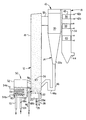
- the reference numeral 10 refers, in general, to the fluidized bed steam generation system of the present invention which includes a furnace section 12, a separating section 14, and a heat recovery area 16.
- the furnace section 12 includes an upright enclosure 18 and an plenum 20 disposed at the lower end portion of the enclosure for receiving a gas, such as air, from an external source.
- An air distributor, or grate, 22 is provided at the interface between the lower end of the enclosure 18 and the air plenum 20 for allowing the pressurized air from the plenum to pass upwardly through the enclosure 18.
- Particulate material is supported on the air distributor 22, extends for the entire height of the enclosure 18 and has a density that decreases with height.
- One or more inlets such as an inlet 24, are provided through the walls of the enclosure 18 for introducing a particulate material into the bed.
- An air conduit 26 is connected between a source of pressurized air (not shown) and the plenum 20 for introducing the air into the plenum under control of a damper 26a located in the plenum.
- the air from the plenum 20 fluidizes the particulate material in the enclosure 18 and, according to a preferred embodiment, the velocity of the air is of a magnitude to create a circulating fluidized bed as described above.
- a drain pipe 28 registers with an opening in the air distributor 22 and/or the walls of the enclosure 18 for discharging spent particulate material from the enclosure.
- the particulate material can include coal and relatively fine particles of an adsorbent material, such as limestone, for absorbing the sulfur generated during the combustion of the coal, in a known manner.
- the walls of the enclosure 18 include a plurality of water tubes disposed in a vertically extending relationship and that flow circuitry (not shown) is provided to pass water through the tubes to convert the water to steam. Since the construction of the walls of the enclosure 18 is conventional, the walls will not be described in any further detail.
- the separating section 14 includes one or more cyclone separators 30 provided adjacent the enclosure 10 and connected thereto by ducts 32 which extend from openings formed in the upper portion of the rear wall of the enclosure 18 to an inlet opening formed in the upper portion of the separator 30.
- the separator 30 receives the flue gases and entrained particulate material from the fluidized bed in the enclosure 18 and operates in a conventional manner to disengage the particulate material from the flue gases due to the centrifugal forces created in the separator.
- the separated flue gases rise in the separator 30 and pass into and through the heat recovery area 16.
- the heat recovery area 16 includes an enclosure 34 housing superheater 36, a reheater 38 and an economizer 40, all of which are formed by a plurality of heat exchange tubes 42 extending in the path of the gases that pass through the enclosure 34. It is understood that the tubes 42 forming the superheater 36, the reheater 38 and the economizer 40 all are formed into bundles connected between an inlet header 44a and an outlet header 44b which, in turn, are connected to additional fluid flow circuitry (not shown) extending from the tubes forming the walls of the furnace section 12 to receive heated water or vapor for further heating. After passing through the superheater 36, the reheater 38, and the economizer 40, the gases exit the enclosure 34 through an outlet 44 formed in the rear wall thereof.
- the separated solids from the separator 30 pass into a hopper 30a connected to the lower end of the separator and then into a dipleg 46 connected to the outlet of the hopper.
- the dipleg 46 extends through a rear wall of the enclosure 18 for discharging the suparated solids back to the fluidized bed.
- the dipleg 46 has a U-shaped portion 46a for preventing the backflow of solids and/or gases directly from the furnace section 12 to the separator 30.
- An external heat exchanger 50 is provided adjacent the front wall of the enclosure 18 and includes a vessel, or housing 52 having a bundle of heat exchange tubes 54 extending therein.
- the housing 52 is formed from either water wall tubes on a refractory lined metal enclosure.
- the tubes 54 extend between an inlet header 54a and an outlet header 54b which, in turn, are connected to the aforementioned fluid flow circuitry in a manner to be described.
- An inlet conduit 56 extends from the wall of the enclosure 18 to the lower portion of the housing 52 for transferring solid particles from the fluidized bed in the enclosure 18 to the housing 52.
- An outlet conduit 58 extends from the upper portion of the housing 52 to any of the walls of the enclosure 18 for returning the solid particles to the enclosure 18.
- An air distributor 60 extends horizontally in the lower portion of the housing 52 to define an air plenum 62.
- Two conduits 64 and 66 receive gas, such as air, from an external source and communicate with the plenum 62 and the inlet conduit 56, respectively.
- This external source could be flue gases from a location downstream of the furnace.
- Control dampers 68a and 68b are disposed in the ducts 64 and 66, respectively, to control the flow of air into the air plenum 62 and into the inlet pipe 56, respectively.
- a drain pipe 70 extends from the distributor 60 to remore coarse materials from the housing 52.
- Hot particulate material can thus be continuously fed into the housing 52 via the conduit 56 and is fluidized by the air from the plenum 62 passing through the distributor 60. Water is passed through the tubes 54 to remove heat from the particulate material and the fluidizing air entrains the relatively fine particles and carries them upwardly in the housing 52 before they exit the housing and pass, via the outlet conduit 58 back into the enclosure 18 for mixing with the particles in the enclosure.
- particulate fuel material from the inlet 24 is introduced into the enclosure 18 and adsorbent material can also be introduced in a similar manner, as needed.
- Pressurized air from an external source passes into and through the conduit 27, the air plenum 20, through the air distributor 22 and into the particulate material in the enclosure 18 to fluidize the material.
- a lightoff burner (not shown), or the like, is disposed in the duct leading to the enclosure 18 and is fired to ignite the particulate fuel material. When the temperature of the material reaches an acceptably high level, additional fuel from the inlet 24 is discharged into the enclosure 18.
- the material in the enclosure 18 is self-combusted by the heat in the furnace section 12 and the mixture of air and gaseous products of combustion (hereinafter referred to as "flue gases") passes upwardly through the enclosure 18 and entrain, or elutriate, the particulate material in the enclosure.
- flue gases mixture of air and gaseous products of combustion
- the velocity of the air introduced into the plenum 20, via the conduit 26 passes through the air distributor 22 and into the interior of the enclosure 18 controlled by adjustment of the damper 26a in accordance with the size of the particulate material in the enclosure 18 so that a circulating fluidized bed is formed, i.e. the particulate material is fluidized to an extent that substantial entrainment or elutriation of the particulate material in the bed is achieved.
- the flue gases passing into the upper portion of the enclosure 18 are substantially saturated with the particulate material.
- the saturated flue gases pass to the upper portion of the enclosure 18 and exit through the duct 32 and pass into the cyclone separator 30.
- the solid particulate material is separated from the flue gases and the former passes through the hopper 30 and passes, via the dipleg 46 back into the enclosure 18 where it mixes with the particulate material in the furnace section 12.
- the cleaned flue gases from the separator 30 pass upwardly and exit to the heat recovery area 16 for passage through the enclosure 34 and across the superheater 36, the reheater 38 and the economizer 40, before exiting through the outlet 44 to external equipment.
- the control damper 68b is opened as desired to introduce air into the conduit 56 to promote the flow of particulate material from the enclosure 18 to the enclosure 52. Additional air, under the control of the damper 68a, is introduced into the plenum 62 which passes upwardly through the air distributor 60 and fluidizes the particulate material in housing 52. The velocity of the air and therefore the degree of flow of material into the housing 52 and the degree of fluidization and the resultant height of the material in the housing are respectively controlled as needed by varying the position of the dampers 68a and 68b.
- the particulate material builds up in the housing 52 to a level at least sufficient to cover the bundle of tubes 54, and a portion of the particulate material is entrained by the fluidizing air and exits, via the conduit 58 and is introduced back into the enclosure 18.
- Water is passed through the tubes forming the walls of the enclosure 18, the heat exchange tubes 42 forming the superheater 36, the reheater 38 and the economizer 40 and the heat exchange tubes 54 in the external heat exchanger 50 to extract heat from the particulate material in the enclosure 18 and the heat exchanger 50 and from the flue gases in the heat recovery area 16, to progressively convert the water to steam.
- the amount of heat added to the water or steam passing through the tubes 54 of the heat exchanger 50 can be controlled by controlling the fraction of the total material flow that passes through the housing 52 which, in turn, can be controlled by varying the fluidizing velocity of the air by the damper 64a of the air inlet conduit 64.
- the headers 54a and 54b of the heat exchange tubes 54 can be connected in the flow circuit in a manner to supplement the heat added to the water or steam in the heat recovery area.
- the outlet of the superheater 38 could be connected to the inlet header 54a of the heat exchange tubes 54 so that the demands on the superheater would be satisfied.
Landscapes
- Chemical & Material Sciences (AREA)
- Engineering & Computer Science (AREA)
- Combustion & Propulsion (AREA)
- Organic Chemistry (AREA)
- Chemical Kinetics & Catalysis (AREA)
- Physics & Mathematics (AREA)
- Thermal Sciences (AREA)
- Mechanical Engineering (AREA)
- General Engineering & Computer Science (AREA)
- Fluidized-Bed Combustion And Resonant Combustion (AREA)
Applications Claiming Priority (2)
| Application Number | Priority Date | Filing Date | Title |
|---|---|---|---|
| US07/386,181 US4947804A (en) | 1989-07-28 | 1989-07-28 | Fluidized bed steam generation system and method having an external heat exchanger |
| US386181 | 1989-07-28 |
Publications (3)
| Publication Number | Publication Date |
|---|---|
| EP0410773A2 true EP0410773A2 (de) | 1991-01-30 |
| EP0410773A3 EP0410773A3 (de) | 1991-03-27 |
| EP0410773B1 EP0410773B1 (de) | 1994-01-19 |
Family
ID=23524514
Family Applications (1)
| Application Number | Title | Priority Date | Filing Date |
|---|---|---|---|
| EP90308239A Revoked EP0410773B1 (de) | 1989-07-28 | 1990-07-27 | Wirbelbettdampferzeugungssystem und Verfahren mit einem aussen liegenden Wärmetauscher |
Country Status (7)
| Country | Link |
|---|---|
| US (1) | US4947804A (de) |
| EP (1) | EP0410773B1 (de) |
| JP (1) | JPH0395303A (de) |
| CN (1) | CN1050257A (de) |
| CA (1) | CA1318196C (de) |
| ES (1) | ES2050377T3 (de) |
| PT (1) | PT94830A (de) |
Cited By (4)
| Publication number | Priority date | Publication date | Assignee | Title |
|---|---|---|---|---|
| EP0595487A1 (de) * | 1992-10-26 | 1994-05-04 | Foster Wheeler Energy Corporation | Wirbelschichtreaktor mit Strippergaskühler und Verfahren zum Betrieb desselben |
| EP0628767A2 (de) * | 1993-05-11 | 1994-12-14 | Foster Wheeler Energy Corporation | Wirbelschicht-Reaktor und Verfahren zur Verwendung von Brennstoff aus Abfall |
| WO1996005469A1 (en) * | 1994-08-17 | 1996-02-22 | Foster Wheeler Energia Oy | Fluidized bed reactor and method of operation thereof |
| WO1999015829A1 (en) * | 1997-09-22 | 1999-04-01 | Combustion Engineering, Inc. | Fluid bed ash cooler |
Families Citing this family (40)
| Publication number | Priority date | Publication date | Assignee | Title |
|---|---|---|---|---|
| US5141708A (en) * | 1987-12-21 | 1992-08-25 | Foster Wheeler Energy Corporation | Fluidized bed combustion system and method having an integrated recycle heat exchanger |
| US5022893A (en) * | 1990-03-01 | 1991-06-11 | Foster Wheeler Energy Corporation | Fluidized bed steam temperature enhancement system |
| US5069170A (en) * | 1990-03-01 | 1991-12-03 | Foster Wheeler Energy Corporation | Fluidized bed combustion system and method having an integral recycle heat exchanger with inlet and outlet chambers |
| US5133943A (en) * | 1990-03-28 | 1992-07-28 | Foster Wheeler Energy Corporation | Fluidized bed combustion system and method having a multicompartment external recycle heat exchanger |
| US5054436A (en) * | 1990-06-12 | 1991-10-08 | Foster Wheeler Energy Corporation | Fluidized bed combustion system and process for operating same |
| US5069171A (en) * | 1990-06-12 | 1991-12-03 | Foster Wheeler Agency Corporation | Fluidized bed combustion system and method having an integral recycle heat exchanger with a transverse outlet chamber |
| US5385104A (en) * | 1990-07-03 | 1995-01-31 | Volund Ecology Systems A/S | Method and apparatus for incinerating different kinds of solid and possibly liquid waste material |
| US5040492A (en) * | 1991-01-14 | 1991-08-20 | Foster Wheeler Energy Corporation | Fluidized bed combustion system and method having a recycle heat exchanger with a non-mechanical solids control system |
| US5095854A (en) * | 1991-03-14 | 1992-03-17 | Foster Wheeler Development Corporation | Fluidized bed reactor and method for operating same utilizing an improved particle removal system |
| US5181481A (en) * | 1991-03-25 | 1993-01-26 | Foster Wheeler Energy Corporation | Fluidized bed combustion system and method having multiple furnace sections |
| US5140950A (en) * | 1991-05-15 | 1992-08-25 | Foster Wheeler Energy Corporation | Fluidized bed combustion system and method having an integral recycle heat exchanger with recycle rate control and backflow sealing |
| US5239945A (en) * | 1991-11-13 | 1993-08-31 | Tampella Power Corporation | Apparatus to reduce or eliminate combustor perimeter wall erosion in fluidized bed boilers or reactors |
| US5218931A (en) * | 1991-11-15 | 1993-06-15 | Foster Wheeler Energy Corporation | Fluidized bed steam reactor including two horizontal cyclone separators and an integral recycle heat exchanger |
| JPH05141637A (ja) * | 1991-11-25 | 1993-06-08 | Ebara Corp | 流動床焼却プラントとその運転方法 |
| US5218932A (en) * | 1992-03-02 | 1993-06-15 | Foster Wheeler Energy Corporation | Fluidized bed reactor utilizing a baffle system and method of operating same |
| US5237963A (en) * | 1992-05-04 | 1993-08-24 | Foster Wheeler Energy Corporation | System and method for two-stage combustion in a fluidized bed reactor |
| US5239946A (en) * | 1992-06-08 | 1993-08-31 | Foster Wheeler Energy Corporation | Fluidized bed reactor system and method having a heat exchanger |
| US5510085A (en) * | 1992-10-26 | 1996-04-23 | Foster Wheeler Energy Corporation | Fluidized bed reactor including a stripper-cooler and method of operating same |
| US5332553A (en) * | 1993-04-05 | 1994-07-26 | A. Ahlstrom Corporation | Method for circulating solid material in a fluidized bed reactor |
| US5299532A (en) * | 1992-11-13 | 1994-04-05 | Foster Wheeler Energy Corporation | Fluidized bed combustion system and method having multiple furnace and recycle sections |
| US5390612A (en) * | 1993-03-01 | 1995-02-21 | Foster Wheeler Energy Corporation | Fluidized bed reactor having a furnace strip-air system and method for reducing heat content and increasing combustion efficiency of drained furnace solids |
| JP2939338B2 (ja) * | 1993-04-05 | 1999-08-25 | フォスター ホイーラー エナージア オサケ ユキチュア | 流動床反応装置およびその製造方法 |
| US5347954A (en) * | 1993-07-06 | 1994-09-20 | Foster Wheeler Energy Corporation | Fluidized bed combustion system having an improved pressure seal |
| AU2976995A (en) * | 1994-07-15 | 1996-02-16 | Aalborg Industries A/S | A fluid-bed heat exchanger, fluid-bed combustion reactor systems and methods for the operation of a fluid-bed heat exchanger and a fluid-bed combustion reactor system |
| US5735682A (en) * | 1994-08-11 | 1998-04-07 | Foster Wheeler Energy Corporation | Fluidized bed combustion system having an improved loop seal valve |
| US5463968A (en) * | 1994-08-25 | 1995-11-07 | Foster Wheeler Energy Corporation | Fluidized bed combustion system and method having a multicompartment variable duty recycle heat exchanger |
| US5682828A (en) * | 1995-05-04 | 1997-11-04 | Foster Wheeler Energy Corporation | Fluidized bed combustion system and a pressure seal valve utilized therein |
| FI103582B (fi) * | 1997-12-19 | 1999-07-30 | Valtion Teknillinen | Menetelmä metallia sekä orgaanista ainesta sisältävän materiaalin käsi ttelemiseksi, johon sisältyy metallin erotus |
| AT505526B1 (de) * | 2007-08-14 | 2010-09-15 | Univ Wien Tech | Wirbelschichtreaktorsystem |
| CN101929672B (zh) * | 2009-06-24 | 2012-10-24 | 中国科学院工程热物理研究所 | 一种u形水冷返料器 |
| US8689709B2 (en) * | 2011-05-04 | 2014-04-08 | Southern Company | Oxycombustion in transport oxy-combustor |
| KR101264793B1 (ko) | 2011-06-20 | 2013-05-15 | 한국에너지기술연구원 | 하부루프실을 구비한 유동층 반응장치 |
| ITRM20130029A1 (it) * | 2013-01-18 | 2014-07-19 | Magaldi Power Spa | Impianto e metodo di estrazione e raffreddamento di ceneri con incremento dell'efficienza complessiva di caldaia. |
| CN104595879A (zh) * | 2015-02-02 | 2015-05-06 | 中国海洋石油总公司 | 一种提高注蒸汽锅炉换热系数的方法 |
| US20170356642A1 (en) * | 2016-06-13 | 2017-12-14 | The Babcock & Wilcox Company | Circulating fluidized bed boiler with bottom-supported in-bed heat exchanger |
| CN106052308B (zh) * | 2016-06-15 | 2018-11-13 | 成都昊特新能源技术股份有限公司 | 一种利用汽机乏汽的干燥系统以及干燥方法 |
| FI129147B (en) * | 2017-12-19 | 2021-08-13 | Valmet Technologies Oy | Fluidized bed boiler with gas lock heat exchanger |
| KR101984542B1 (ko) * | 2017-12-21 | 2019-06-03 | 한국에너지기술연구원 | 압력과 밀도 차이를 이용하는 유동층 고체순환장치, 및 그 고체순환장치를 갖는 유동층 반응시스템 및 고체순환방법 |
| KR102093302B1 (ko) * | 2018-07-19 | 2020-04-23 | 한국생산기술연구원 | 복수의 라이저부를 구비한 유동사 하강형 순환유동층 보일러 및 이의 운전방법 |
| CN109827171B (zh) * | 2019-03-15 | 2024-03-08 | 镇江东亚碳素焦化有限公司 | 一种石油焦燃烧脱硫用流化床锅炉 |
Citations (5)
| Publication number | Priority date | Publication date | Assignee | Title |
|---|---|---|---|---|
| GB2032598A (en) * | 1978-10-03 | 1980-05-08 | Foster Wheeler Energy Corp | Cooling material discharged from fluidized beds |
| EP0062092A2 (de) * | 1981-03-27 | 1982-10-13 | Deutsche Babcock Aktiengesellschaft | Wirbelschichtfeuerung mit einem Aschekühler |
| EP0068301A1 (de) * | 1981-07-01 | 1983-01-05 | Deutsche Babcock Anlagen Aktiengesellschaft | Dampferzeuger mit zirkulierender atmosphärischer oder druckaufgeladener Wirbelschichtfeuerung |
| GB2132500A (en) * | 1982-12-17 | 1984-07-11 | Coal Ind | Classification and recycling of fluidised bed material |
| US4829912A (en) * | 1988-07-14 | 1989-05-16 | Foster Wheeler Energy Corporation | Method for controlling the particulate size distributions of the solids inventory in a circulating fluidized bed reactor |
Family Cites Families (11)
| Publication number | Priority date | Publication date | Assignee | Title |
|---|---|---|---|---|
| JPS581741B2 (ja) * | 1979-07-20 | 1983-01-12 | 株式会社日立製作所 | ミクロセル用マスクを備えたセルホ−ルダ |
| US4565139A (en) * | 1984-09-12 | 1986-01-21 | Stearns Catalytic World Corp. | Method and apparatus for obtaining energy |
| FI85414C (fi) * | 1985-01-29 | 1992-04-10 | Ahlstroem Oy | Anordning foer avskiljning av fast material ur roekgaserna fraon en reaktor med cirkulerande baedd. |
| US4809623A (en) * | 1985-08-07 | 1989-03-07 | Foster Wheeler Energy Corporation | Fluidized bed reactor and method of operating same |
| FI853464A0 (fi) * | 1985-09-11 | 1985-09-11 | Ahlstroem Oy | Reaktor med cirkulerande baedd. |
| FI86105C (fi) * | 1985-11-19 | 1992-07-10 | Ahlstroem Oy | Foerfarande och anordning foer reglering av en virvelbaeddsreaktors funktion. |
| US4682567A (en) * | 1986-05-19 | 1987-07-28 | Foster Wheeler Energy Corporation | Fluidized bed steam generator and method of generating steam including a separate recycle bed |
| US4665864A (en) * | 1986-07-14 | 1987-05-19 | Foster Wheeler Energy Corporation | Steam generator and method of operating a steam generator utilizing separate fluid and combined gas flow circuits |
| US4732113A (en) * | 1987-03-09 | 1988-03-22 | A. Ahlstrom Corporation | Particle separator |
| DE3715516A1 (de) * | 1987-05-09 | 1988-11-17 | Inter Power Technologie | Wirbelschichtfeuerung |
| US4854249A (en) * | 1987-08-03 | 1989-08-08 | Institute Of Gas Technology | Two stage combustion |
-
1989
- 1989-07-28 US US07/386,181 patent/US4947804A/en not_active Expired - Lifetime
- 1989-09-26 CA CA000613274A patent/CA1318196C/en not_active Expired - Fee Related
-
1990
- 1990-07-26 PT PT94830A patent/PT94830A/pt not_active Application Discontinuation
- 1990-07-27 EP EP90308239A patent/EP0410773B1/de not_active Revoked
- 1990-07-27 ES ES90308239T patent/ES2050377T3/es not_active Expired - Lifetime
- 1990-07-27 JP JP2198070A patent/JPH0395303A/ja active Pending
- 1990-07-28 CN CN90106960A patent/CN1050257A/zh active Pending
Patent Citations (5)
| Publication number | Priority date | Publication date | Assignee | Title |
|---|---|---|---|---|
| GB2032598A (en) * | 1978-10-03 | 1980-05-08 | Foster Wheeler Energy Corp | Cooling material discharged from fluidized beds |
| EP0062092A2 (de) * | 1981-03-27 | 1982-10-13 | Deutsche Babcock Aktiengesellschaft | Wirbelschichtfeuerung mit einem Aschekühler |
| EP0068301A1 (de) * | 1981-07-01 | 1983-01-05 | Deutsche Babcock Anlagen Aktiengesellschaft | Dampferzeuger mit zirkulierender atmosphärischer oder druckaufgeladener Wirbelschichtfeuerung |
| GB2132500A (en) * | 1982-12-17 | 1984-07-11 | Coal Ind | Classification and recycling of fluidised bed material |
| US4829912A (en) * | 1988-07-14 | 1989-05-16 | Foster Wheeler Energy Corporation | Method for controlling the particulate size distributions of the solids inventory in a circulating fluidized bed reactor |
Non-Patent Citations (1)
| Title |
|---|
| VGB KRAFTWERKSTECHNIK, vol. 67, no. 5, May 1987, pages 437-443, Essen, DE; L. PLASS et al.: "Die Entwicklung der ZAWS der Umweltfreundlichen Feuerungstechnik" * |
Cited By (5)
| Publication number | Priority date | Publication date | Assignee | Title |
|---|---|---|---|---|
| EP0595487A1 (de) * | 1992-10-26 | 1994-05-04 | Foster Wheeler Energy Corporation | Wirbelschichtreaktor mit Strippergaskühler und Verfahren zum Betrieb desselben |
| EP0628767A2 (de) * | 1993-05-11 | 1994-12-14 | Foster Wheeler Energy Corporation | Wirbelschicht-Reaktor und Verfahren zur Verwendung von Brennstoff aus Abfall |
| EP0628767A3 (de) * | 1993-05-11 | 1995-04-19 | Foster Wheeler Energy Corp | Wirbelschicht-Reaktor und Verfahren zur Verwendung von Brennstoff aus Abfall. |
| WO1996005469A1 (en) * | 1994-08-17 | 1996-02-22 | Foster Wheeler Energia Oy | Fluidized bed reactor and method of operation thereof |
| WO1999015829A1 (en) * | 1997-09-22 | 1999-04-01 | Combustion Engineering, Inc. | Fluid bed ash cooler |
Also Published As
| Publication number | Publication date |
|---|---|
| CA1318196C (en) | 1993-05-25 |
| CN1050257A (zh) | 1991-03-27 |
| JPH0395303A (ja) | 1991-04-19 |
| EP0410773B1 (de) | 1994-01-19 |
| PT94830A (pt) | 1992-03-31 |
| US4947804A (en) | 1990-08-14 |
| EP0410773A3 (de) | 1991-03-27 |
| ES2050377T3 (es) | 1994-05-16 |
Similar Documents
| Publication | Publication Date | Title |
|---|---|---|
| US4947804A (en) | Fluidized bed steam generation system and method having an external heat exchanger | |
| EP0365723B1 (de) | Wirbelschichtreaktor mit integriertem Rückführungswärmeaustauscher | |
| US5141708A (en) | Fluidized bed combustion system and method having an integrated recycle heat exchanger | |
| EP0518482B1 (de) | Anlage zur Wirbelschichtverbrennung | |
| EP0574176B1 (de) | Einen Wärmeaustauscher aufweisendes Wirbelbettreaktorsystem und -verfahren | |
| US5218932A (en) | Fluidized bed reactor utilizing a baffle system and method of operating same | |
| CA2041985C (en) | Fluidized bed combustion system and process for operating same | |
| EP0444926A2 (de) | Wirbelbettverbrennung mit einem integrierten Rezirkulationswärmetauscher mit Eintritts- und Austrittskammer | |
| EP0633429B1 (de) | Wirbelbett-Dampferzeugungssystem und Verfahren unter Verwendung von rückgeführten Abgasen zum Erleichtern des Feststoffdurchgangs durch den Tauchverschluss | |
| EP0679837B1 (de) | Druckwirbelschicht-Feuerung mit integriertem Rezirkulationswärmetauscher | |
| US5471955A (en) | Fluidized bed combustion system having a heat exchanger in the upper furnace | |
| US5269263A (en) | Fluidized bed reactor system and method of operating same | |
| EP0399803A1 (de) | Zirkulierender Wirbelbettreaktor mit integrierten gebogenen Armseparatoren | |
| EP0503917B1 (de) | Wirbelbettreaktor und Verfahren zu ihrem Betrieb unter Anwendung eines Teilchenbeseitigungssystem | |
| EP0517495B1 (de) | Wirbelschichtverbrennungsverfahren mit Zufuhr von fein- und grobkörnigen Absorptionsmittelteilchen | |
| US5242662A (en) | Solids recycle seal system for a fluidized bed reactor | |
| US5510085A (en) | Fluidized bed reactor including a stripper-cooler and method of operating same | |
| EP0595487A1 (de) | Wirbelschichtreaktor mit Strippergaskühler und Verfahren zum Betrieb desselben | |
| US5347954A (en) | Fluidized bed combustion system having an improved pressure seal | |
| US5022893A (en) | Fluidized bed steam temperature enhancement system | |
| EP0413612B1 (de) | Wirbelbettdampferzeuger mit dampfgekühltem Zyklonabscheider | |
| EP0398718B1 (de) | Dichtungssystem für Feststoffrückführung in einem Wirbelbettreaktor | |
| CA1309898C (en) | Fluidized bed reactor having an integrated recycle heat exchanger | |
| JPH0642941B2 (ja) | 一体型再循環熱交換器を有する流動床反応装置及びその操作方法 |
Legal Events
| Date | Code | Title | Description |
|---|---|---|---|
| PUAI | Public reference made under article 153(3) epc to a published international application that has entered the european phase |
Free format text: ORIGINAL CODE: 0009012 |
|
| AK | Designated contracting states |
Kind code of ref document: A2 Designated state(s): ES GB IT NL |
|
| PUAL | Search report despatched |
Free format text: ORIGINAL CODE: 0009013 |
|
| AK | Designated contracting states |
Kind code of ref document: A3 Designated state(s): ES GB IT NL |
|
| 17P | Request for examination filed |
Effective date: 19910924 |
|
| 17Q | First examination report despatched |
Effective date: 19920423 |
|
| GRAA | (expected) grant |
Free format text: ORIGINAL CODE: 0009210 |
|
| AK | Designated contracting states |
Kind code of ref document: B1 Designated state(s): ES GB IT NL |
|
| ITF | It: translation for a ep patent filed | ||
| REG | Reference to a national code |
Ref country code: ES Ref legal event code: FG2A Ref document number: 2050377 Country of ref document: ES Kind code of ref document: T3 |
|
| PG25 | Lapsed in a contracting state [announced via postgrant information from national office to epo] |
Ref country code: GB Effective date: 19940727 |
|
| PG25 | Lapsed in a contracting state [announced via postgrant information from national office to epo] |
Ref country code: ES Free format text: LAPSE BECAUSE OF NON-PAYMENT OF DUE FEES Effective date: 19940728 |
|
| PLBI | Opposition filed |
Free format text: ORIGINAL CODE: 0009260 |
|
| PLBI | Opposition filed |
Free format text: ORIGINAL CODE: 0009260 |
|
| 26 | Opposition filed |
Opponent name: DEUTSCHE BABCOCK AKTIENGESELLSCHAFT Effective date: 19941011 |
|
| 26 | Opposition filed |
Opponent name: L. & C. STEINMUELLER GMBH Effective date: 19941018 Opponent name: DEUTSCHE BABCOCK AKTIENGESELLSCHAFT Effective date: 19941011 |
|
| NLR1 | Nl: opposition has been filed with the epo |
Opponent name: DEUTSCHE BABCOCK AKTIENGESELLSCHAFT |
|
| PG25 | Lapsed in a contracting state [announced via postgrant information from national office to epo] |
Ref country code: NL Effective date: 19950201 |
|
| NLR1 | Nl: opposition has been filed with the epo |
Opponent name: L. & C. STEINMULLER GMBH |
|
| NLV4 | Nl: lapsed or anulled due to non-payment of the annual fee | ||
| GBPC | Gb: european patent ceased through non-payment of renewal fee |
Effective date: 19940727 |
|
| RDAG | Patent revoked |
Free format text: ORIGINAL CODE: 0009271 |
|
| STAA | Information on the status of an ep patent application or granted ep patent |
Free format text: STATUS: PATENT REVOKED |
|
| 27W | Patent revoked |
Effective date: 19950622 |