EP0410683A2 - Kraftangetriebene Verriegelungseinrichtung - Google Patents
Kraftangetriebene Verriegelungseinrichtung Download PDFInfo
- Publication number
- EP0410683A2 EP0410683A2 EP90308074A EP90308074A EP0410683A2 EP 0410683 A2 EP0410683 A2 EP 0410683A2 EP 90308074 A EP90308074 A EP 90308074A EP 90308074 A EP90308074 A EP 90308074A EP 0410683 A2 EP0410683 A2 EP 0410683A2
- Authority
- EP
- European Patent Office
- Prior art keywords
- keeper
- pin member
- keeper member
- shank portion
- pin
- Prior art date
- Legal status (The legal status is an assumption and is not a legal conclusion. Google has not performed a legal analysis and makes no representation as to the accuracy of the status listed.)
- Withdrawn
Links
Images



Classifications
-
- B—PERFORMING OPERATIONS; TRANSPORTING
- B60—VEHICLES IN GENERAL
- B60J—WINDOWS, WINDSCREENS, NON-FIXED ROOFS, DOORS, OR SIMILAR DEVICES FOR VEHICLES; REMOVABLE EXTERNAL PROTECTIVE COVERINGS SPECIALLY ADAPTED FOR VEHICLES
- B60J7/00—Non-fixed roofs; Roofs with movable panels, e.g. rotary sunroofs
-
- B—PERFORMING OPERATIONS; TRANSPORTING
- B60—VEHICLES IN GENERAL
- B60J—WINDOWS, WINDSCREENS, NON-FIXED ROOFS, DOORS, OR SIMILAR DEVICES FOR VEHICLES; REMOVABLE EXTERNAL PROTECTIVE COVERINGS SPECIALLY ADAPTED FOR VEHICLES
- B60J7/00—Non-fixed roofs; Roofs with movable panels, e.g. rotary sunroofs
- B60J7/185—Locking arrangements
-
- E—FIXED CONSTRUCTIONS
- E05—LOCKS; KEYS; WINDOW OR DOOR FITTINGS; SAFES
- E05B—LOCKS; ACCESSORIES THEREFOR; HANDCUFFS
- E05B81/00—Power-actuated vehicle locks
- E05B81/12—Power-actuated vehicle locks characterised by the function or purpose of the powered actuators
- E05B81/20—Power-actuated vehicle locks characterised by the function or purpose of the powered actuators for assisting final closing or for initiating opening
Definitions
- the present invention concerns automotive latching systems. More particularly, the present invention concerns powered latching systems. Even more particularly, the present invention concerns powered latching systems for convertible tops, trunk lids, tonneau covers and the like.
- the present invention provides a power latching system which overcomes the deficiencies in the prior art.
- the present invention provides a power latching mechanism comprising:
- manually operable means for disengaging the pin member from the keeper member is provided.
- the present invention will be described with reference to a convertible top for a vehicle, the present invention evidences other utility wherever a powered pull down latching arrangement is desired.
- the present invention in addition to latching convertible tops, the present invention is useful in latching powered T-tops, deck lids and the like.
- the latching assembly hereof can be used to tie down the rearwardmost bow in a convertible-type vehicle.
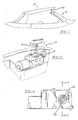
- FIG. 1 there is depicted therein an automobile 10 having a convertible or foldable top 12.
- convertible or foldable tops generally, comprise a fabric covering secured to a plurality of bows or struts which traverse the width of the vehicle and are foldable rearwardly and forwardly through a plurality of linkages which interconnect the various bows or struts which carry the fabric.
- the actual construction of the convertible top and the linkage system for the folding and unfolding thereof does not form part of the present invention, per se.
- a first embodiment of a power latch mechanism in accordance with the present invention shown generally at 19, comprises a pin member 20, and also a keeper member 21 comprising a hollow cylindrical body which receives the pin member 20.
- the keeper member 21 has a cylindrical passageway 17 formed therein and the passageway 17 has a substantially circular inner periphery in cross section as shown in FIG. 4.
- the keeper member 21 has two thread windings 60, 62 therein which are disposed oppositely across from one another at any given height.
- the mechanism 19 of the present invention includes means, such as e.g., an electric motor 23 acting together with gears, for rotatably urging engagement between the pin member 20 and the keeper member 21, as shown in FIG. 10, and as will be described in further detail herein.
- the electric motor 23 turns a worm gear 40 which is affixed to the shaft thereof, to turn drive gears 48, 49 which in turn operate the driven gear 42 which is attached by screws 45 to the keeper member 21, thereby threadedly engaging the pin member 20 and keeper member 21 when the keeper member 21 is rotated in a first direction.
- gears having different diameters such as 42, 48, and 49 are used, this increases the torque applied to the keeper member over what it would be using only a single gear, due to the differing gear diameters.
- the motor 23 will rotate the keeper member 21 in a second direction to disengage the pin member 20 therefrom.
- the worm gear 40 may turn the driven gear 42 directly.
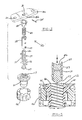
- the pin member 20 comprises a base portion 30 for mounting the pin member 20 to a convertible top 12 or other vehicle surface using suitable fasteners (not shown) in mounting holes 32.
- the pin member 20 further comprises a shank portion 26 which attaches to the base portion 30 and depends therefrom, the shank portion 26 having an enlarged end 27 opposite the base portion 30.
- the shank portion 26 is attached to the base portion 30 by any suitable means, such as e.g. by forming an asymmetrical hole 31 in the base portion 30, the hole 31 corresponding to the shape of the shank portion 26 so as to receive it therein.
- An allen screw 35 or other threaded fastener threadably engages with a threaded hole 36 which communicates with the asymmetrical hole 31.
- the allen screw or similar fastener is tightened in the threaded hole 36 until it abuts tightly against the shank portion 26 to hold it in place.
- the pin member 20 also comprises a retaining sleeve 28 which surrounds the shank portion 26, biasing means such as a coil spring 29 or the like to force the retaining sleeve 28 downwardly on the shank portion 26, and may include, but does not require, a collar such as that shown at 33 in order to cover and protect the spring 29.
- biasing means such as a coil spring 29 or the like to force the retaining sleeve 28 downwardly on the shank portion 26, and may include, but does not require, a collar such as that shown at 33 in order to cover and protect the spring 29.
- a plurality of engaging members 37 fit into trough-shaped recesses 38 in the sides of the shank portion 26, one engaging member 37 for each recess 38, and the engaging members 37 are held therein by the retaining sleeve 28 which fits over the shank portion 26.
- the engaging members 37 fit in apertures 39 which are formed in the sides of the sleeve 28, and the engaging members 37 are too large to pass completely through the apertures 39, which correspond in number and location to the recesses 38 and are sized slightly smaller than the engaging members 37 to prevent the engaging members 37 from passing therethrough.
- the apertures 39 are chamfered to provide a close fit for the engaging members 37 therein.
- the recesses 38 are shallow at their ends toward the enlarged end 27 and reach a maximum depth at their ends toward the base portion 30. This maximum depth is slightly less than the height of one engaging member 37.
- the recesses 38 are oriented parallel to the longitudinal axis of the shank portion 26. In the illustrated embodiment of FIGS. 4-8, the engaging members are located horizontally opposite one another at approximately the same height on the shank portion 26.
- the spring 29 acts as a means for biasing the retaining sleeve 28 against the enlarged end 27 of the shank portion 26 which acts as a stop to retain the sleeve 28 on the shank portion 26.
- the sleeve thus biased, keeps the engaging members 37 in the shallow ends of the recesses 38, to force the engaging members 37 outwardly, thus, either retaining the engaging members 37 in the threads 22 inside the keeper member 21 to prevent disengagement of the pin member 20 from the keeper member 21, or allowing for threadable engagement between the pin member 20 and the keeper member 21 when the switch 50 activates the means for rotating in a first direction when the members 20, 21 are initially being rotatably and threadably engaged.
- the two engaging members 37 which are closest to the enlarged end 27 of the shank portion are simultaneously engaged in opposite thread windings 60, 62 inside the keeper member 21 as shown in FIG. 6.
- the thread windings 60, 62 exert downward pressure on the engaging members 37 to draw the shank portion 26 into the keeper member 21 as shown by the arrows in FIG. 6.
- the location of the engaging members 37 is arranged and dimensioned so that the engaging members fit engagingly into the opposite thread windings 60, 62 inside the keeper member 21 and act as male threads on the exterior of the pin member 20.
- the location and the arrangement of the engaging members 37 on the shank portion 26 may be varied by design, according to the needs of a particular application, so long as the engaging members 37 fit within the threads 60, 62 formed in the walls of the passageway 17 inside the keeper member 21 to ensure engagement of the pin member 20 in the keeper member 21.
- the cooperation between the threads 60, 62 of the keeper member 21 and the engaging members 37 provides a means for selectively retaining the pin member 20 in the keeper member 21.
- the engaging members 37 may be vertically spaced on the shank portion 26 at a convenient distance which allows sufficient space therebetween for the trough-shaped recesses 38.
- the spacing of the engaging members 37 on the shank portion 26 must be dimensioned to allow alignment of the engaging members 37 with threads 60, 62 of the keeper member when the pin member 20 advances sufficiently into the keeper member to bring each successive pair of engaging members 37 into proximity with the threads 60, 62 of the keeper member 21.
- the pin member 20 can be manually inserted into the keeper member 21 without rotation of either member as shown in Figs. 7 and 8.
- the retaining sleeve 28 slides up the shank portion 26 toward the base portion 30, allowing the engaging members 37 to move deeper into the recesses 38 until they are flush with the outside of the sleeve 28 when in the deep ends of the recesses 38, thus allowing the engaging members 37 to temporarily bypass the threads 60, 62 inside the keeper member 21 as shown in FIG. 8 and allowing the pin 20 to be fully engaged with the keeper member 21.
- the keeper member 21 retentively engages the pin member 20 when the pin member 20 is manually inserted thereinto without rotating either member.
- the motor 23 and gears 40, 42, 48, and 49 together constitute a means for rotating the keeper member 21 to urge engagement between it and the pin member 20.
- a conventional battery 51 acts as a power source for energizing the means for rotating, and a switch 50 is included in the circuit for selectively connecting the power source to the means for rotating and for determining the direction of rotation of the keeper member 21, either by closing a forward circuit 52 which polarizes the motor 23 to actuate the means for rotating in a first direction and to rotatably and threadedly engage the pin member 20 in the keeper member 21, or alternatively, by closing a reverse circuit 53 which reverses the polarity to the motor 23 to actuate the means for rotating in a second direction and to rotatably and threadedly disengage the pin member 20 from the keeper member 21.
- a second embodiment of the, power latch mechanism of the present invention shown generally at 119, comprises a pin member 120, and a keeper member 121 comprising a hollow cylindrical body which receives the pin member 120 therein.
- the pin member 120 has threads 122 formed therearound on the exterior surface thereof.
- the mechanism also includes means, such as e.g., an electric motor 123 acting together with gears 140, 142, 148, 149, for rotatably urging engagement between the pin member 120 and the keeper member 121 as will be described in further detail herein.
- the electric motor 123 turns a worm gear 140 which is attached to the shaft thereof to turn drive gears 148, 149 which in turn operate the driven gear 142 which is attached by screws 145 to the keeper member 121.
- the motor 123 thereby threadedly engages the pin member 120 and keeper member 121 when turned in a first direction.
- the pin member 120 comprises a base portion or plate 130 for mounting the pin member 120 to a convertible top 112 or other vehicle surface using suitable fasteners (not shown) in mounting holes 132 which are formed in the plate 130.
- the pin member 120 further comprises a cylindrical shank portion 126 which attaches to the base portion 130 and depends therefrom, the shank portion 126 having threads 122 formed therearound for engaging with a keeper member 121.
- the shank portion 126 may be attached to the base portion 130 by any suitable means, or may be formed integrally therewith.
- the keeper member 121 comprises a hollow cylindrical body with a cylindrical passageway 117 formed therein for receiving the pin member 120.
- the keeper member 121 has rectangular openings 137, 138 formed in opposed sides thereof. Disposed within the recesses 137, 138 are a pair of opposed pawls 127, 128 which engagingly fit into the threads 122 of the pin member 120 to selectively retain the pin member 120 in the keeper member 121 as will be further described herein.
- the keeper member 121 has a circumferential flange 101 extending radially outwardly therefrom above the recesses 137, 138; and the flange 101 may have a plurality of holes 104 formed therethrough for attaching the cylindrical body 117 to the driven gear 142 by the use of threaded fasteners 145 passing through the holes 104 and vertically into threaded holes 105 formed in the driven gear 142.
- the pawls 127, 128 are generally opposed curved bodies and have inclined ramp portions 106, 108 on the innermost surfaces thereof, the ramp portions 106, 108 being inclined at the same angle as that of the threads 122 on the pin member 120, which may be in a range of 20-60°.
- the ramp portions 106, 108 have substantially flattened faces 107, 109 respectively on the lower surfaces thereof which engage the threads 122 of the pin member 120, and downwardly sloping faces 165, 167 respectively on the upper surfaces thereof to facilitate manual insertion of the pin member 120 into the keeper member 121.
- the upper faces 165, 167 of the ramp portion 107, 108 may slope downwardly at a 45° angle.
- each of the pawls has a notch 210, 212 respectively formed along the length thereof.
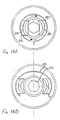
- a pair of cam follower projections 114, 116 Located within the notches 110, 112 as seen in phantom in FIGS. 14A and 14B are a pair of cam follower projections 114, 116 respectively.
- the driven gear 142 has a radially inwardly projected flange 156 formed at the lower surface thereof on which rests a cam driver tube 139, which is of a generally cylindrical shape and has a pair of opposed cams 218, 220 projecting radially and transversely outwardly therefrom as seen in FIG. 3.
- the cams 218, 220 are disposed in the notches 210, 212 of the pawls 127, 128 as shown in phantom in FIG. 4A.
- a resilient spring band 129 surrounds the cylindrical member 117 around the pawls 127, 128 just below the flange 101 and serves to bias the pawls 127, 128 inwardly.
- the spring band 129 cooperates with the pawls 127, 128 to selectively retain the shank portion 126 of the pin memver 120 in engagement with the keeper member 121 once the two members 120, 121 are fully engaged.
- a geometric recess 222 Formed at the bottom of the cam driver tube 129 may be a geometric recess 222 as shown in FIG. 4B.
- the geometric recess 222 is a female hex fitting.
- An allen wrench or other suitable tool may be installed into the recess 222 to manually rotate the cam driver tube 139. Rotation of the tube 149 pushes the cams 218, 220 against the cam follower projections 114, 116 to move the pawls 127, 128 radially outwardly with respect to one another to allow for disengagement of the pin member 120 from the keeper member 121.
- FIGS. 14A and 14B This rotation of the cam driver tube 139 to cause outward movement of the pawls 127, 128 is illustrated in FIGS. 14A and 14B. Distortion of the spring band 129 is exaggerated in FIG. 14B for purposes of illustration.
- a keeper housing 186 having an upper section 224 and a lower section 226 is provided to house the components of the keeper member 121 and the drive gears 148, 149.
- the upper section 224 is attached to the lower section 226 by suitable fasteners such as screws 228 of which one is illustrated.
- the motor 123 may be attached to the housing 186 by suitable fasteners such as screws 230 of which one is illustrated.
- the pin member 120 can be manually inserted into the keeper member 121 without rotation thereof as shown in FIGS. 15A and 15B.
- the pawls 127, 128 are pushed outwardly by the shank 126 of the pin member 120 and move into the recesses 137, 138 in the cylinder 117, thus allowing the shank 126 to temporarily bypass the pawls 127, 128 inside the keeper member 121 and allowing the pin 120 to be fully engaged with the keeper member 121 without rotation of either the pin member 120 or the keeper member 121.
- the spring 129 and pawls together provide a means for selectively retaining the pin member 120 in the keeper member 121 to prevent manual disengagement of the latching mechanism of the present invention until the motor 123 is energized by the switch 150 to turn in a second direction to rotatably and threadedly disengage the pin 120 from the keeper 121, or until a suitable tool is inserted into the geometric recess 222 and the cam driver tube 139 is manually rotated.
- the keeper member 121 retentively engages the pin member 120 when the pin member 120 is manually inserted thereinto.
- the motor 123 and gears 140, 142, 148, and 149 together constitute a means for rotating the cylindrical body 117 of the keeper member 121 to urge engagement between it and the pin member 120.
- a battery 151 acts as a power source for energizing the means for rotating, and a switch 150 is included in the circuit for selectively connecting the power source to the means for rotating and for determinging the direction of rotation of the keeper member 121, either by closing a forward circuit 152 which polarizes the motor 123 to actuate the means for rotating in a first direction and to rotatably and threadedly engage the pin member 120 in the keeper member 121, or alternatively, by closing a reverse circuit 153 which reverses the polarity to the motor 123 to actuate the means for rotating in a second direction and to rotatably and threadedly disengage the pin member 120 from the keeper member 121.
Landscapes
- Engineering & Computer Science (AREA)
- Mechanical Engineering (AREA)
- Lock And Its Accessories (AREA)
- Fittings On The Vehicle Exterior For Carrying Loads, And Devices For Holding Or Mounting Articles (AREA)
- Dowels (AREA)
Applications Claiming Priority (2)
| Application Number | Priority Date | Filing Date | Title |
|---|---|---|---|
| US38549589A | 1989-07-26 | 1989-07-26 | |
| US385495 | 1989-07-26 |
Publications (2)
| Publication Number | Publication Date |
|---|---|
| EP0410683A2 true EP0410683A2 (de) | 1991-01-30 |
| EP0410683A3 EP0410683A3 (en) | 1992-05-13 |
Family
ID=23521616
Family Applications (1)
| Application Number | Title | Priority Date | Filing Date |
|---|---|---|---|
| EP19900308074 Withdrawn EP0410683A3 (en) | 1989-07-26 | 1990-07-24 | Power latch system |
Country Status (4)
| Country | Link |
|---|---|
| EP (1) | EP0410683A3 (de) |
| JP (1) | JPH03221680A (de) |
| KR (1) | KR910002630A (de) |
| AU (1) | AU5980890A (de) |
Cited By (4)
| Publication number | Priority date | Publication date | Assignee | Title |
|---|---|---|---|---|
| EP0529288A1 (de) * | 1991-08-28 | 1993-03-03 | WEBASTO KAROSSERIESYSTEME GmbH | Dachanordnung für ein Kraftfahrzeug |
| DE4314146A1 (de) * | 1993-04-29 | 1994-11-03 | Webasto Karosseriesysteme | Vorrichtung zum Verstellen von bewegbaren Teilen an Fahrzeugen |
| WO2007137684A1 (de) * | 2006-05-26 | 2007-12-06 | Bayerische Motoren Werke Aktiengesellschaft | Zentriereinrichtung für ein kraftfahrzeug mit einem falt- oder klappverdeck oder hardtop |
| US11529856B2 (en) * | 2018-12-21 | 2022-12-20 | Geof Spear | Quick release system for a vehicle hard top |
Families Citing this family (3)
| Publication number | Priority date | Publication date | Assignee | Title |
|---|---|---|---|---|
| JP4538221B2 (ja) * | 2003-12-19 | 2010-09-08 | トーシンテック株式会社 | 車両ドアの自動閉止装置 |
| KR100748457B1 (ko) * | 2007-04-25 | 2007-08-10 | 두얼메카닉스 주식회사 | 가전제품의 도어락 장치 |
| CN105691977B (zh) * | 2016-01-25 | 2017-12-26 | 湖南晟通天力汽车有限公司 | 厢式货车防盗装置及厢式货车 |
Family Cites Families (2)
| Publication number | Priority date | Publication date | Assignee | Title |
|---|---|---|---|---|
| FR2608664B1 (fr) * | 1986-12-23 | 1994-12-09 | Peugeot | Dispositif de fermeture et d'ouverture assiste pour elements articules de vehicules automobiles |
| US4819983A (en) * | 1987-09-24 | 1989-04-11 | Asc Incorporated | Power latch system |
-
1990
- 1990-07-24 EP EP19900308074 patent/EP0410683A3/en not_active Withdrawn
- 1990-07-25 AU AU59808/90A patent/AU5980890A/en not_active Abandoned
- 1990-07-26 KR KR1019900011416A patent/KR910002630A/ko not_active Withdrawn
- 1990-07-26 JP JP2198972A patent/JPH03221680A/ja active Pending
Cited By (6)
| Publication number | Priority date | Publication date | Assignee | Title |
|---|---|---|---|---|
| EP0529288A1 (de) * | 1991-08-28 | 1993-03-03 | WEBASTO KAROSSERIESYSTEME GmbH | Dachanordnung für ein Kraftfahrzeug |
| DE4128460A1 (de) * | 1991-08-28 | 1993-03-04 | Webasto Ag Fahrzeugtechnik | Dachanordnung fuer ein kraftfahrzeug |
| DE4314146A1 (de) * | 1993-04-29 | 1994-11-03 | Webasto Karosseriesysteme | Vorrichtung zum Verstellen von bewegbaren Teilen an Fahrzeugen |
| WO2007137684A1 (de) * | 2006-05-26 | 2007-12-06 | Bayerische Motoren Werke Aktiengesellschaft | Zentriereinrichtung für ein kraftfahrzeug mit einem falt- oder klappverdeck oder hardtop |
| US7566090B2 (en) | 2006-05-26 | 2009-07-28 | Bayerische Motoren Werke Aktiengesellschaft | Centering device for a motor vehicle having a retractable or detachable top |
| US11529856B2 (en) * | 2018-12-21 | 2022-12-20 | Geof Spear | Quick release system for a vehicle hard top |
Also Published As
| Publication number | Publication date |
|---|---|
| AU5980890A (en) | 1991-01-31 |
| KR910002630A (ko) | 1991-02-25 |
| EP0410683A3 (en) | 1992-05-13 |
| JPH03221680A (ja) | 1991-09-30 |
Similar Documents
| Publication | Publication Date | Title |
|---|---|---|
| US5186516A (en) | Power latch system | |
| US4819983A (en) | Power latch system | |
| US11725428B2 (en) | Power actuator with self disengaging clutch unit | |
| US5782118A (en) | Lockset with motorized system for locking and unlocking | |
| US6915671B2 (en) | Apparatus for locking a motor-vehicle steering shaft | |
| US7121126B2 (en) | Apparatus for locking a motor-vehicle steering shaft | |
| US7572018B2 (en) | Folding mechanism for exterior rear-view mirrors of automotive vehicles | |
| EP1296844B1 (de) | Betätigungsvorrichtung für tankklappe | |
| US4972692A (en) | Key-operated ignition device | |
| US5893439A (en) | Parking mechanism for a vehicle equipped with an automatic transmission | |
| DE102021107177A1 (de) | Türsystem mit türpräsentatorsteuerung | |
| US10099629B2 (en) | Deployable sensor assembly | |
| EP0410683A2 (de) | Kraftangetriebene Verriegelungseinrichtung | |
| US11365567B2 (en) | Power child lock system for vehicle | |
| US5450737A (en) | Removable lock handle assembly | |
| GB2320051A (en) | Actuating device for a locking system | |
| US20020112934A1 (en) | Hub lock mechanism | |
| US4696382A (en) | Front wheel hub clutch | |
| US5684670A (en) | Control switch or signaling unit control panel mounting arrangement | |
| US4913486A (en) | Sunroof and latching assembly therefor | |
| EP1389356A2 (de) | Elektromechanisches stellglied und kupplung dafür | |
| US20200063468A1 (en) | Latch assembly having integral fasteners and method of assembling same | |
| EP0798163B1 (de) | Fahrzeug-Aussenspiegel | |
| GB2204351A (en) | Locking device for vehicle | |
| AU718189B1 (en) | A lock assembly |
Legal Events
| Date | Code | Title | Description |
|---|---|---|---|
| PUAI | Public reference made under article 153(3) epc to a published international application that has entered the european phase |
Free format text: ORIGINAL CODE: 0009012 |
|
| AK | Designated contracting states |
Kind code of ref document: A2 Designated state(s): DE ES FR GB IT |
|
| PUAL | Search report despatched |
Free format text: ORIGINAL CODE: 0009013 |
|
| AK | Designated contracting states |
Kind code of ref document: A3 Designated state(s): DE ES FR GB IT |
|
| 17P | Request for examination filed |
Effective date: 19921002 |
|
| STAA | Information on the status of an ep patent application or granted ep patent |
Free format text: STATUS: THE APPLICATION HAS BEEN WITHDRAWN |
|
| 18W | Application withdrawn |
Withdrawal date: 19930708 |