EP0410129A2 - Cutting tool - Google Patents
Cutting tool Download PDFInfo
- Publication number
- EP0410129A2 EP0410129A2 EP90111502A EP90111502A EP0410129A2 EP 0410129 A2 EP0410129 A2 EP 0410129A2 EP 90111502 A EP90111502 A EP 90111502A EP 90111502 A EP90111502 A EP 90111502A EP 0410129 A2 EP0410129 A2 EP 0410129A2
- Authority
- EP
- European Patent Office
- Prior art keywords
- eccentric
- cutting tool
- tool according
- base body
- cutting
- Prior art date
- Legal status (The legal status is an assumption and is not a legal conclusion. Google has not performed a legal analysis and makes no representation as to the accuracy of the status listed.)
- Granted
Links
- 238000005520 cutting process Methods 0.000 title claims abstract description 65
- 230000002093 peripheral effect Effects 0.000 claims description 5
- 238000004519 manufacturing process Methods 0.000 description 6
- 230000000717 retained effect Effects 0.000 description 3
- 238000003754 machining Methods 0.000 description 2
- 238000010276 construction Methods 0.000 description 1
- 230000007423 decrease Effects 0.000 description 1
- 238000006073 displacement reaction Methods 0.000 description 1
- 238000005553 drilling Methods 0.000 description 1
- 230000000694 effects Effects 0.000 description 1
- 238000007654 immersion Methods 0.000 description 1
- 230000007774 longterm Effects 0.000 description 1
- 238000005259 measurement Methods 0.000 description 1
- 238000000034 method Methods 0.000 description 1
- 238000003801 milling Methods 0.000 description 1
- 230000002265 prevention Effects 0.000 description 1
Images

Classifications
-
- B—PERFORMING OPERATIONS; TRANSPORTING
- B23—MACHINE TOOLS; METAL-WORKING NOT OTHERWISE PROVIDED FOR
- B23C—MILLING
- B23C5/00—Milling-cutters
- B23C5/16—Milling-cutters characterised by physical features other than shape
- B23C5/20—Milling-cutters characterised by physical features other than shape with removable cutter bits or teeth or cutting inserts
- B23C5/22—Securing arrangements for bits or teeth or cutting inserts
- B23C5/24—Securing arrangements for bits or teeth or cutting inserts adjustable
- B23C5/2479—Securing arrangements for bits or teeth or cutting inserts adjustable the adjusting means being eccentrics
-
- B—PERFORMING OPERATIONS; TRANSPORTING
- B23—MACHINE TOOLS; METAL-WORKING NOT OTHERWISE PROVIDED FOR
- B23C—MILLING
- B23C5/00—Milling-cutters
- B23C5/16—Milling-cutters characterised by physical features other than shape
- B23C5/20—Milling-cutters characterised by physical features other than shape with removable cutter bits or teeth or cutting inserts
- B23C5/22—Securing arrangements for bits or teeth or cutting inserts
- B23C5/2204—Securing arrangements for bits or teeth or cutting inserts with cutting inserts clamped against the walls of the recess in the cutter body by a clamping member acting upon the wall of a hole in the insert
- B23C5/2226—Securing arrangements for bits or teeth or cutting inserts with cutting inserts clamped against the walls of the recess in the cutter body by a clamping member acting upon the wall of a hole in the insert for plate-like cutting inserts fitted on an intermediate carrier, e.g. shank fixed in the cutter body
-
- B—PERFORMING OPERATIONS; TRANSPORTING
- B23—MACHINE TOOLS; METAL-WORKING NOT OTHERWISE PROVIDED FOR
- B23C—MILLING
- B23C5/00—Milling-cutters
- B23C5/16—Milling-cutters characterised by physical features other than shape
- B23C5/20—Milling-cutters characterised by physical features other than shape with removable cutter bits or teeth or cutting inserts
- B23C5/22—Securing arrangements for bits or teeth or cutting inserts
- B23C5/24—Securing arrangements for bits or teeth or cutting inserts adjustable
Definitions
- the invention relates to a cutting tool with the features specified in the preamble of claim 1.
- the at least one cutting plate is indirectly adjustable in two predetermined directions by means of two rotationally adjustable eccentrics approximately at right angles to one another, in that the at least one cutting plate is accommodated in the insert holder, also referred to as a cassette , which in turn is adjustable in the mentioned directions via the two eccentrics.
- the two eccentrics are contained in approximately V-shaped guide grooves of the plate holder and are supported on flat support surfaces of the base body.
- the two eccentrics should be connected to the plate holder by springs, the springs being designed as ring springs in such a way that each eccentric can be rotated for adjustment purposes.
- the spring force of the springs should be dimensioned such that the eccentric does not change its setting position when smaller forces act on the eccentric from outside in the removed state. This securing of the eccentrics in the axial direction is inadequate.
- the eccentrics can fall out of their V-shaped guide grooves in the plate holder. For example, the eccentrics are then released, if the plate holder is removed from the base body, since the eccentrics only dip into the V-shaped guide grooves at most with a maximum circumferential angle of 180 ° and therefore become free during disassembly, especially since the ring springs in the immersion area of the eccentrics do not get into the V-shaped guide grooves can develop sufficient holding power.
- the eccentrics are already at risk of falling out when the fixed tension of the holding plate on the base body is loosened. This alone prevents or at least impairs a quick and reliable setting of the tool.
- Another disadvantage is that the loss prevention by ring springs is complex and expensive to manufacture. For each eccentric, corresponding ring grooves have to be worked in to accommodate the ring springs, which means a large manufacturing effort.
- the ring springs are individual elements that also entail additional costs. There is also a greater assembly effort, since the ring springs have to be inserted into the assigned grooves of the eccentric. Finally, there is a risk that the ring springs will weaken or break over time.
- the invention has for its object to provide a cutting tool of the type mentioned in the preamble of claim 1, which has a simple, reliable and cost-effective captive device for at least one eccentric.
- the adjustability of rotation is particularly smooth, since no forces are required transversely between the eccentric on the one hand and the bearing points and support surfaces of the eccentric to secure the loss of the at least one eccentric, which at the same time could otherwise impair the smoothness of the rotary adjustment due to increased frictional force.
- the invention is also a particularly smooth and thus sensitive rotation adjustment of the eccentric guaranteed.
- a relatively narrow circumferential incision may be sufficient as the groove.
- the incision width is chosen so that the end section, which projects coaxially at the end of the other eccentric, is still in the groove when this eccentric bearing the end section is rotated about its longitudinal axis and in the receptacle of the base body and / or Plate holder is displaced more or less strongly across its longitudinal axis.
- the eccentric bearing the end section can be held captively in a simple manner within the receptacle in that the free end of the receptacle is closed with a blind cap which is arranged sufficiently firmly.
- the plate holders can be assembled together with the eccentrics and at least one cutting plate to be attached as a ready-to-install unit without the at least one eccentric threatens to fall out of the plate holder in the axial direction, since this is prevented by the captive engagement of the two eccentric ends.
- the other eccentric can thereby be secured against slipping out of the receptacle in the plate holder that behind the free end of the eccentric some projection protrudes transversely into the receptacle in the plate holder and secures this eccentric against slipping out in this one axial direction.
- the invention is suitable for all possible shapes and structures of cutting tools, as well as for the direct attachment of cutting plates in associated seats of the base body. Even if the invention is illustrated with the aid of a insert holder on which at least one insert is exchangeably fastened, it goes without saying that this particular insert holder is also dispensed with and the at least one insert can be adjusted directly via the eccentrics and supported on the base body. If the inserts are attached using insert holders, it goes without saying that each insert holder can also hold several inserts.
- a cutting tool 10 is shown schematically, which can be of any design, for example as a drilling tool, in particular as a countersinking tool, as a milling tool, as a reaming tool or the like. can be designed, each tool can be single-edged or multi-edged.
- the invention can be used with any type of cutting tool 10 and is not restricted to a particular type of this tool, which is why it is ultimately not a question of the special design of the cutting tool 10.
- the cutting tool 10 has a base body 11 which e.g. has a plurality of individual cutting plates 12 which are attached to the base body 11 in an adjustable and lockable manner.
- a base body 11 which e.g. has a plurality of individual cutting plates 12 which are attached to the base body 11 in an adjustable and lockable manner.
- only one insert 12 can be seen, which is approximately square in this case, with cutters 13-16 being formed on all four sides, so that the insert 12 can be placed as a so-called indexable insert, so that one or the other other cutting edge 13 - 16 is effective for machining.
- the cutting plate 12 is fastened to its own plate holder 17, also referred to as a cassette.
- the plate holder 17 is approximately rectangular and for this purpose is provided in the area of a corner with a step-like recessed seat 18, which has a base 19 and two to each other, e.g. has right-angled side surfaces 20 and 21.
- the insert 12 placed in the seat 18 thus lies flat with its back surface against the base surface 19 and with two sides against the side surfaces 20 and 21, so that a defined and firm fit is ensured.
- the plate holder 17 contains a threaded bore 22 into which a fastening screw 23, e.g. Torx screw is screwed in, which passes through the cutting plate 12 and can be received sunk therein with its head.
- the plate holder 17 is in turn adjustable and fixable in an assigned and suitable seat 24 of the base body 11, as is known in such cutting tools 10. Details of the seat 24 in Base body 11 therefore need no special description.
- the seat 24 has a base surface 25 and two lateral support surfaces 26 and 27, for example extending approximately at right angles to one another and projecting from the base surface 25, which are, for example, flat.
- In the area of the seat 24 there is an oblique through hole 28 through which a clamping screw 29 can reach from the rear, which then engage from the rear of the plate holder 17 into a threaded hole 30 contained in the latter and thus firmly tighten the plate holder 17 with its back when tightened can attract the base surface 25 and also in the transverse direction against the support surfaces 26, 27.
- the threaded bore 30 in the plate holder 17 has the same oblique course as the through hole 28.
- the latter can be provided on the side facing away from the plate holder 17 with a depression 31 for receiving the head 32 of the clamping screw 29. Due to this rear fastening of the plate holder 17 in the seat 24, the head 32 of the clamping screw 29 is not in the chest area and where the chips are produced during the machining operation. The head 32 is thereby protected against damage and clogging of its tool engagement surface with chips or the like. protected.
- this rear attachment via the threaded bore 30 in the plate holder 17 has the advantage that the plate holder 17 can be kept smaller; because the through hole 28, for example, larger for this fastening by means of the clamping screw 29 and the depression 31 intended for receiving the head 32 are located in the base body 11 and not in the plate holder 17, which otherwise requires more space in the plate holder 17 and in a larger construction of the plate holder 17 for these reasons alone.
- the plate holder 17 (cassette) for fastening the cutting plate 12 is omitted.
- the cutting plate 12 is accommodated directly in a seat of the base body 11 corresponding to its size, analogous to the illustrated holding of the plate holder 17 in the seat 24.
- the cutting plate 12 is either fastened directly by means of a fastening screw 23 which engages in a threaded bore in the base body 11, or a clamping plate is provided which is supported on the base body 11 and is clamped thereon with a fastening screw and presses on the cutting plate 12 and presses it into it Holds seat in the base body 11.
- Such attachments of the cutting plate 12 directly in an associated seat in the base body 11 are known per se. These are also within the scope of the invention - even if further details are explained using the example of fastening by means of the plate holder 17 shown.
- the cutting tool 10 has two bolt-shaped eccentrics 33 and 34 which are directed transversely to one another, in particular are approximately at right angles to one another.
- Each eccentric 33, 34 can be rotated about its longitudinal axis 35 or 36 and is supported on the one hand on the base body 11 and on the other hand on the plate holder 17. It is understood that in the mentioned embodiment, not shown, in which each insert 12 is held directly in an associated seat in the base body 11, each eccentric 33, 34 then, instead of the insert holder 17, rests directly on the side of the insert 12, so that these is supported on the base body 11 via the respective eccentric 33, 34.
- eccentric includes every possible configuration in such a way that the rotational distance of the outer circumferential surface 37 or 38 from the longitudinal axis 35 or 36 increases or decreases in one direction or the other when rotating about the longitudinal axis 35 or 36.
- the eccentricity can already be achieved, for example, by flattening 39 or 40 of the peripheral surface 37 or 38.
- the eccentricity can be realized in that the outer peripheral surface 37 or 38 of each eccentric 33 or 34 follows, for example, a spiral, as is made visible in FIGS. 6 and 8 by the enlarged illustration.
- the envelope circle is shown in dash-dot lines.
- One eccentric 33 is supported within an associated receptacle 41 on the upper edge region of the plate holder 17 in FIGS. 1 and 2.
- the receptacle 41 is designed, for example, as a bore 42 which runs continuously, the wall 43 of which points towards the support surface 27 a continuous slot 44 is opened such that the associated eccentric 33 can protrude with a peripheral part through the slot 44 to the outside and can rest on the support surface 27.
- the other eccentric 34 is also mounted in the plate holder 17 in an associated receptacle 45, which is designed as a bore 46, a continuous slot 48 being contained in the wall 47, which faces the support surface 26, through which the bore 46 to the support surface 26 is opened in such a way that the associated eccentric 34 can protrude with a peripheral part through the slot 48 to the outside and can rest on the support surface 26.
- the width of each slot 44 and 48 is smaller than 180 ° circumferential angle and selected so that the eccentric 33 or 34 received therein is held captively in the direction transverse to the bore 42 or 46.
- the respective slot 44 or 48 is provided on the edge area associated with the support surface 27 or 26, it is ensured that the respective eccentric 33 or 34 is supported on at least part of its length with a part protruding and protruding from the bore 42 or 46 on this support surface 27 or 26 of the base body 11.
- the respective eccentric 33 or 34 is in contact with the inner circumferential surface of the bore 42 or 46, so that the forces acting on the plate holder 17 from the outside are absorbed and supported and via the respective eccentric 33 or 34 be passed to the base body 11.
- Both eccentrics 33, 34 run e.g. approximately at right angles to each other.
- one of the eccentrics 33, e.g. axial adjustment and the other eccentric 34 which e.g. radial adjustment of the plate holder 17 - and thus also the cutting plate 12 - serve.
- Each bolt-shaped eccentric 33, 34 is at one end, which is accessible from the outside, with a tool engagement surface 49 or 50, e.g. provided with a slot on which a suitable tool, e.g. a screwdriver that can attack.
- the clamping screw 29 does not need to be loosened, but it can be inserted into the slot 49 of the eccentric 33, for example with a screwdriver and this is rotated in a corresponding, sensible manner about its longitudinal axis 35, with, for example, increasing eccentricity of its outer circumferential surface 37 with respect to the longitudinal axis 35.
- the plate holder 17 together with the cutting plate 12 fixed thereon is displaced along the support surface 26. Because of the effective self-locking Eccentric 33 prevented from adjusting itself in an undesired manner about its longitudinal axis 35, so that the setting made is retained.
- each support surface 26, 27 of the base body 11, which is assigned to the eccentric 34 or 33 is designed as a flat surface.
- this support surface 26, 27 can also be designed as an arcuate, recessed groove, for example.
- each eccentric 33, 34, as described for the plate holder 17 shown can be stored within a receptacle, for example a bore, which instead of in the plate holder 17 in the base body 11 and there in the region of the support surfaces 26 , 27 is provided. Then this hole expediently contains a continuous slot through which the eccentric 33, 34 received therein can protrude in the direction of the plate holder 17.
- the plate holder 17 is simplified since it does not contain any bores 42, 46 for the eccentrics 33, 34, because these bores are displaced into the base body 11.
- This exemplary embodiment described, not shown, is therefore in principle the same arrangement, in which only one exchange is made.
- the plate holder 17 is also omitted for this exemplary embodiment (not shown) and the cutting plate 12 can be fastened directly in an assigned seat in the base body 11, the eccentrics 33, 34 in the bores of the base body 11 then being located directly on the assigned sides of the base plate 11 Fit cutting plate 12 and support it directly on base body 11.
- the two eccentrics 33, 34 abut each other with one end and thereby engage in a form-fitting manner.
- Both eccentrics 33, 34 together form a captive holder for one of the two eccentrics, in the exemplary embodiment shown for the eccentric 33 located at the top in FIG. 1.
- This eccentric 33 has an expediently circumferential groove 51 at one end, which lies opposite the tool engagement surface 49 provided, in which an end portion 52 of the other eccentric 34 engages in the butt region with positive locking of the eccentric 33 in the direction of its longitudinal axis 35.
- the groove 51 is approximately V-shaped in cross section. Instead, it can also be approximately U-shaped or approximately arc-shaped.
- the end section 52 of the eccentric 34 tapers towards the free end. It can be designed to match the cross section of the groove 51. In the exemplary embodiment shown, the end section 52 is approximately frustoconical. It can be advantageous if the end section 52 is essentially of the same shape as the cross section of the groove 51.
- the arrangement is such that the one eccentric 33, which contains the groove 51, with respect to a longitudinal center axis of the base body 11, not shown, e.g. is directed approximately radially and is held captively against the centrifugal force effect during the rotation of the cutting tool 10 by means of the other eccentric 34. In individual cases, this depends on the detailed design of the respective cutting tool 10.
Abstract
Description
Die Erfindung bezieht sich auf ein Zerspanungswerkzeug mit den im Oberbegriff des Anspruchs 1 angegebenen Merkmalen.The invention relates to a cutting tool with the features specified in the preamble of claim 1.
Bei einem bekannten Zerspanungswerkzeug (DE-OS 23 63 902) ist die mindestens eine Schneidplatte über zwei zueinander etwa rechtwinklig stehende, drehverstellbare Exzenter mittelbar dadurch in den beiden vorgegebenen Richtungen verstellbar, daß die mindestens eine Schneidplatte im Plattenhalter, auch als Kassette bezeichnet, aufgenommen ist, der seinerseits über die beiden Exzenter in den genannten Richtungen verstellbar ist. Die beiden Exzenter sind in etwa V-förmigen Führungsnuten des Plattenhalters enthalten und stützen sich an ebenen Stützflächen des Grundkörpers ab. Durch Federn sollen die beiden Exzenter mit dem Plattenhalter verbunden sein, wobei die Federn als Ringfedern ausgebildet sind derart, daß jeder Exzenter zu Verstellzwecken gedreht werden kann. Die Federkraft der Federn soll so bemessen sein, daß der Exzenter seine Einstellage nicht verändert, wenn im ausgebauten Zustand kleinere Kräfte von außen auf den Exzenter wirken. Diese Sicherung der Exzenter in Achsrichtung ist unzulänglich. Die Exzenter können aus ihren V-förmigen Führungsnuten im Plattenhalter herausfallen. So werden die Exzenter z.B. dann frei, wenn der Plattenhalter vom Grundkörper demontiert wird, da die Exzenter nur höchstens etwa mit einer 180° Umfangswinkelerstreckung in die V-förmigen Führungsnuten eintauchen und daher bei der Demontage von selbst frei werden, zumal die Ringfedern im Eintauchbereich der Exzenter in die V-förmigen Führungsnuten nicht genügend Haltekraft entwickeln können. Somit sind also die Exzenter schon beim Lockern der Festspannung der Halteplatte am Grundkörper gegen Herausfallen gefährdet. Bereits dies verhindert oder beeinträchtigt zumindest eine schnelle und zuverlässige Einstellung des Werkzeuges. Von Nachteil ist ferner, daß die Verliersicherung durch Ringfedern fertigungstechnisch aufwendig und teuer ist. Bei jedem Exzenter müssen entsprechende Ringnuten für die Aufnahme der Ringfedern eingearbeitet werden, was einen großen Fertigungsaufwand bedeutet. Außerdem stellen die Ringfedern Einzelelemente dar, die ebenfalls Zusatzkosten bedingen. Es ergibt sich auch ein größerer Montageaufwand, da die Ringfedern in die zugeordneten Nuten der Exzenter eingesetzt werden müssen. Schließlich besteht die Gefahr, daß die Ringfedern im Laufe der Zeit erlahmen oder brechen.In a known cutting tool (DE-OS 23 63 902), the at least one cutting plate is indirectly adjustable in two predetermined directions by means of two rotationally adjustable eccentrics approximately at right angles to one another, in that the at least one cutting plate is accommodated in the insert holder, also referred to as a cassette , which in turn is adjustable in the mentioned directions via the two eccentrics. The two eccentrics are contained in approximately V-shaped guide grooves of the plate holder and are supported on flat support surfaces of the base body. The two eccentrics should be connected to the plate holder by springs, the springs being designed as ring springs in such a way that each eccentric can be rotated for adjustment purposes. The spring force of the springs should be dimensioned such that the eccentric does not change its setting position when smaller forces act on the eccentric from outside in the removed state. This securing of the eccentrics in the axial direction is inadequate. The eccentrics can fall out of their V-shaped guide grooves in the plate holder. For example, the eccentrics are then released, if the plate holder is removed from the base body, since the eccentrics only dip into the V-shaped guide grooves at most with a maximum circumferential angle of 180 ° and therefore become free during disassembly, especially since the ring springs in the immersion area of the eccentrics do not get into the V-shaped guide grooves can develop sufficient holding power. Thus, the eccentrics are already at risk of falling out when the fixed tension of the holding plate on the base body is loosened. This alone prevents or at least impairs a quick and reliable setting of the tool. Another disadvantage is that the loss prevention by ring springs is complex and expensive to manufacture. For each eccentric, corresponding ring grooves have to be worked in to accommodate the ring springs, which means a large manufacturing effort. In addition, the ring springs are individual elements that also entail additional costs. There is also a greater assembly effort, since the ring springs have to be inserted into the assigned grooves of the eccentric. Finally, there is a risk that the ring springs will weaken or break over time.
Der Erfindung liegt die Aufgabe zugrunde, eine Zerspanungswerkzeug der im Oberbegriff des Anspruchs 1 genannten Art zu schaffen, das für zumindest einen Exzenter eine einfache, zuverlässige und kostengünstige Verliersicherung aufweist.The invention has for its object to provide a cutting tool of the type mentioned in the preamble of claim 1, which has a simple, reliable and cost-effective captive device for at least one eccentric.
Die Aufgabe ist bei einem Zerspanungswerkzeug der im Oberbegriff des Anspruchs 1 genannten Art erfindungsgemäß durch die Merkmale im Kennzeichnungsteil des Anspruchs 1 gelöst.The object is achieved according to the invention in a cutting tool of the type mentioned in the preamble of claim 1 by the features in the characterizing part of claim 1.
Dadurch, daß die beiden Exzenter mit je einem Ende aneinanderstoßen und formschlüssig ineinandergreifen, ist für beide, oder zumindest für einen Exzenter, durch diesen Formschluß eine Verliersicherung gegeben, so daß der Exzenter daran gehindert ist, aus seiner Aufnahme herauszurutschen. Die Verliersicherung bleibt erhalten, auch wenn die im Grundkörper festgespannte Schneidplatte oder der eine daran befestigte Schneidplatte tragende, im Grundkörper festgespannte Plattenhalter zu Verstellzwecken gelockert wird. Auch während der Verstellung durch Drehen des einen oder anderen Exzenters bleibt dieser formschlüssige Eingriff beider Exzenterenden erhalten und damit die so erreichte Verliersicherung für zumindest einen der beiden Exzenter. Von Vorteil ist ferner, daß der formschlüssige Eingriff beider Exzenterenden die Verstellung der Exzenter in keiner Weise behindert. Es sind keine besonderen zusätzlichen Einzelteile für diese Verliersicherung notwendig. Die Anzahl der Bauteile ist somit reduziert. Mangels solcher besteht auch nicht die Gefahr, daß diese im Laufe der Zeit funktionsuntüchtig werden. Somit ist auf Dauer eine zuverlässige Verliersicherung für zumindest einen der beiden Exzenter gegeben. Diese benötigt auch keinen größeren zusätzlichen Fertigungsaufwand; denn die für den formschlüssigen Eingriff beider aneinanderstoßenden Exzenterenden notwendigen Teile lassen sich praktisch bei der Herstellung der Exzenter gleich mit einarbeiten. Da besondere Sicherungselemente in Form von zusätzlichen Einzelteilen entfallen, entfällt dafür auch ein zusätzlicher Montageschritt. Das Zerspanungswerkzeug ist also insgesamt kostengünstiger, einfacher zu montieren und ermöglicht eine schnelle, zuverlässige und leichte Einstellung durch Drehverstellung der einzelnen Exzenter. Die Drehverstellbarkeit ist besonders leichtgängig, da für die Verliersicherung des zumindest einen Exzenters keine Kräfte quer zwischen dem Exzenter einerseits und den Lagerstellen und Abstützflächen dieses andererseits benötigt werden, die zugleich durch erhöhte Reibkraft sonst die Leichtgängigkeit bei der Drehverstellung beeinträchtigen könnten. Somit ist durch die Erfindung auch eine besonders leichtgängige und somit feinfühlige Drehverstellbarkeit der Exzenter gewährleistet.The fact that the two eccentrics abut each other with one end and interlock positively is through for both, or at least for one eccentric this positive locking is given a captive lock, so that the eccentric is prevented from slipping out of its receptacle. The securing against loss is retained even if the cutting plate clamped in the base body or the plate holder carrying a cutting plate fastened to it is loosened for adjustment purposes. Even during the adjustment by turning one or the other eccentric, this form-fitting engagement of both eccentric ends is retained and thus the loss protection achieved in this way for at least one of the two eccentrics. Another advantage is that the positive engagement of both eccentric ends in no way hinders the adjustment of the eccentric. No special additional parts are required for this loss protection. The number of components is thus reduced. In the absence of such, there is no danger that they will become inoperable over time. In the long term, this ensures reliable loss protection for at least one of the two eccentrics. This also does not require any major additional manufacturing effort; because the parts necessary for the positive engagement of both abutting eccentric ends can be practically incorporated in the manufacture of the eccentric. Since special securing elements in the form of additional individual parts are omitted, an additional assembly step is also unnecessary. The cutting tool is therefore generally less expensive, easier to assemble and enables quick, reliable and easy adjustment by rotating the individual eccentrics. The adjustability of rotation is particularly smooth, since no forces are required transversely between the eccentric on the one hand and the bearing points and support surfaces of the eccentric to secure the loss of the at least one eccentric, which at the same time could otherwise impair the smoothness of the rotary adjustment due to increased frictional force. Thus, the invention is also a particularly smooth and thus sensitive rotation adjustment of the eccentric guaranteed.
Weitere vorteilhafte Erfindungsmerkmale ergeben sich aus den Ansprüchen 2 - 7. Die insbesondere umlaufende Nut am einen Exzenterende und der z.B. daran angepaßte Endabschnitt am anderen Exzenterende stellen einfache Elemente für den formschlüssigen Eingriff und für die Verliersicherung des einen Exzenters dar. Gesichert ist dadurch derjenige Exzenter, der die Nut enthält, da der in diese Nut quer eingreifende Endabschnitt des anderen Exzenters ein formschlüssiges Sicherungselement bildet, das diesen mit der Nut versehenen Exzenter formschlüssig gegen Verschiebung in Richtung seiner Längsachse sichert. Im Rahmen der Erfindung liegt natürlich auch eine entsprechende Sicherung derart, daß ein eigenständiges Teil, z.B. ein Vorsprung, Stift, Bolzen od.dgl., in die Nut am Ende des einen Exzenters eingreift, wobei dieser eigenständige Teil den Endabschnitt des anderen Exzenters bildet, an dem dieser Teil entweder gleich bei der Herstellung oder nachträglich, z.B. lösbar, angebracht ist. Als Nut kann ein relativ schmaler umlaufender Einschnitt ausreichend sein. Die Einschnittbreite ist dabei so gewählt, daß der Endabschnitt, der koaxial am Ende des anderen Exzenters vorspringt, auch dann noch in der Nut Platz findet, wenn dieser den Endabschnitt tragende Exzenter um seine Längsachse drehverstellt wird und in der Aufnahme des Grundkörpers und/oder des Plattenhalters quer zu seiner Längsachse mehr oder weniger stark versetzt wird. Der den Endabschnitt tragende eine Exzenter kann in einfacher Weise innerhalb der Aufnahme dadurch verliersicher gehalten sein, daß das freie Ende der Aufnahme mit einer Blindkappe verschlossen wird, die ausreichend fest angeordnet ist. Es kann aber auch ausreichend sein, nach Einsetzen des Exzenters in die diesen aufnehmende Aufnahme endseitig einen Sicherungsring oder einen irgendwie ge arteten Vorsprung vorzusehen, der quer hinter dem freien Stirnende dieses Exzenters in die Aufnahme hineinragt und den Exzenter am Herausrutschen aus der Aufnahme hindert. Je nach Einzelfall kann hierzu bereits ein geringfügiges Verstemmen des Wandungsbereiches am freien Ende der jeweiligen Aufnahme ausreichend sein.Further advantageous features of the invention emerge from claims 2-7. The particular circumferential groove on one eccentric end and the end section adapted to it, for example, on the other eccentric end represent simple elements for positive engagement and for securing against loss of the one eccentric. which contains the groove, since the end portion of the other eccentric engaging transversely in this groove forms a positive locking element which positively secures this eccentric provided with the groove against displacement in the direction of its longitudinal axis. Within the scope of the invention there is of course also a corresponding securing such that an independent part, for example a projection, pin, bolt or the like, engages in the groove at the end of one eccentric, this independent part forming the end section of the other eccentric, on which this part is either attached directly during manufacture or subsequently, for example detachably. A relatively narrow circumferential incision may be sufficient as the groove. The incision width is chosen so that the end section, which projects coaxially at the end of the other eccentric, is still in the groove when this eccentric bearing the end section is rotated about its longitudinal axis and in the receptacle of the base body and / or Plate holder is displaced more or less strongly across its longitudinal axis. The eccentric bearing the end section can be held captively in a simple manner within the receptacle in that the free end of the receptacle is closed with a blind cap which is arranged sufficiently firmly. But it may also be sufficient, after inserting the eccentric into the receiving receptacle at the end of a locking ring or somehow ge to provide a projection that protrudes transversely behind the free end of this eccentric into the receptacle and prevents the eccentric from slipping out of the receptacle. Depending on the individual case, a slight caulking of the wall area at the free end of the respective receptacle may be sufficient.
Weitere vorteilhafte Erfindungsmerkmale enthalten die Ansprüche 8 - 17. In den Fällen, in denen die Aufnahmen für die Exzenter in dem Plattenhalter vorgesehen sind, können die Plattenhalter mit den Exzentern und mindestens einer daran zu befestigenden Schneidplatte als einbaufertige Einheit zusammenmontiert werden, ohne daß dabei der zumindest eine Exzenter aus dem Plattenhalter in Achsrichtung herauszufallen droht, da dies durch das verliersichernde Ineinandergreifen beider Exzenterenden verhindert ist. Der andere Exzenter kann dadurch gegen Herausrutschen aus der Aufnahme im Plattenhalter gesichert sein, daß hinter dem freien Ende des Exzenters irgendein Vorsprung in die Aufnahme im Plattenhalter quer vorspringt und diesen Exzenter gegen Herausrutschen in dieser einen Achsrichtung sichert. Ein Herausrutschen in gegensinniger Achsrichtung ist dadurch verhindert, daß dieser Exzenter mit seinem Endabschnitt im Stoßbereich am anderen Exzenter, insbesondere dessen Nut, anstößt. Die Erfindung ist für alle möglichen Formen und Aufbauten von Zerspanungswerkzeugen geeignet, ebenso auch für die unmittelbare Befestigung von Schneidplatten in zugehörigen Sitzen des Grundkörpers. Auch wenn die Erfindung anhand eines Plattenhalters, an dem mindestens eine Schneidplatte auswechselbar befestigt ist, verdeutlicht ist, versteht es sich gleichwohl, daß dieser besondere Plattenhalter auch entfallen und die mindestens eine Schneidplatte jeweils direkt über die Exzenter verstellt und am Grundkörper abgestützt werden kann. Erfolgt die Befestigung der Schneidplatten mittels Plattenhaltern, so versteht es sich, daß jeder Plattenhalter auch mehrere Schneidplatten aufnehmen kann.Further advantageous features of the invention contain claims 8-17. In the cases in which the receptacles for the eccentrics are provided in the plate holder, the plate holders can be assembled together with the eccentrics and at least one cutting plate to be attached as a ready-to-install unit without the at least one eccentric threatens to fall out of the plate holder in the axial direction, since this is prevented by the captive engagement of the two eccentric ends. The other eccentric can thereby be secured against slipping out of the receptacle in the plate holder that behind the free end of the eccentric some projection protrudes transversely into the receptacle in the plate holder and secures this eccentric against slipping out in this one axial direction. Slipping out in the opposite axial direction is prevented by the fact that this eccentric with its end section abuts the other eccentric, in particular its groove, in the joint area. The invention is suitable for all possible shapes and structures of cutting tools, as well as for the direct attachment of cutting plates in associated seats of the base body. Even if the invention is illustrated with the aid of a insert holder on which at least one insert is exchangeably fastened, it goes without saying that this particular insert holder is also dispensed with and the at least one insert can be adjusted directly via the eccentrics and supported on the base body. If the inserts are attached using insert holders, it goes without saying that each insert holder can also hold several inserts.
Weitere Einzelheiten und Vorteile der Erfindung ergeben sich aus der nachfolgenden Beschreibung.Further details and advantages of the invention result from the following description.
Der vollständige Wortlaut der Ansprüche ist vorstehend zur Vermeidung unnötiger Wiederholungen nicht wiedergegeben, sondern statt dessen lediglich durch Nennung der Anspruchsnummern darauf Bezug genommen, wodurch jedoch alle diese Anspruchsmerkmale als an dieser Stelle ausdrücklich und erfindungswesentlich offenbart zu gelten haben. Dabei sind alle in der vorstehenden und folgenden Beschreibung erwähnten Merkmale sowie auch die allein aus der Zeichnung entnehmbaren Merkmale weitere Bestandteile der Erfindung, auch wenn sie nicht besonders hervorgehoben und insbesondere nicht in den Ansprüchen erwähnt sind.To avoid unnecessary repetition, the full wording of the claims is not reproduced above, but instead is referred to instead merely by mentioning the claim numbers, whereby all these features of the claim are to be regarded as being explicitly disclosed here and essential to the invention. All of the features mentioned in the above and the following description, as well as the features that can only be inferred from the drawing, are further components of the invention, even if they are not particularly emphasized and are not mentioned in the claims.
Die Erfindung ist nachfolgend anhand eines in den Zeichnungen gezeigten Ausführungsbeispieles näher erläutert. Es zeigen:
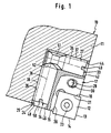
- Fig. 1 einen schematischen Schnitt mit teilweiser Seitenansicht eines Teils eines Zerspanungswerkzeuges mit daran mittelbar über einen Plattenhalter befestigter Schneidplatte,
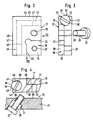
- Fig. 2 eine schematische Vorderansicht allein des Plattenhalters,
- Fig. 3 und 4 jeweils eine schematische Ansicht in Pfeilrichtung III bzw. IV des Plattenhalters in Fig. 2 mit einer Spannschraube zum Befestigen dieser am Zerspanungswerkzeug,
- Fig. 5 eine Seitenansicht eines Exzenters des Zerspanungswerkzeuges in Fig. 1,
- Fig. 6 eine schematische Ansicht in Pfeilrichtung VI des Exzenters in Fig. 5, in demgegenüber wesentlich größerem Maßstab,
- Fig. 7 eine Seitenansicht des zweiten Exzenters der Zerspanungswerkzeuges,
- Fig. 8 eine schematische Ansicht in Pfeilrichtung VIII des Exzenters in Fig. 7, in demgegenüber wesentlich größerem Maßstab.
- 1 is a schematic section with a partial side view of a part of a cutting tool with an insert attached indirectly to it via a insert holder,
- 2 is a schematic front view of the plate holder alone,
- 3 and 4 are each a schematic view in the direction of arrow III and IV of the plate holder in Fig. 2 with a clamping screw for fastening this to the cutting tool,
- 5 is a side view of an eccentric of the cutting tool in Fig. 1,
- 6 is a schematic view in the direction of arrow VI of the eccentric in FIG. 5, on the other hand on a much larger scale,
- 7 is a side view of the second eccentric of the cutting tool,
- Fig. 8 is a schematic view in the direction of arrow VIII of the eccentric in Fig. 7, on the other hand, on a much larger scale.
In Fig. 1 ist schematisch lediglich ein Teil eines Zerspanungswerkzeuges 10 gezeigt, das beliebig ausgebildet sein kann, z.B. als Bohrwerkzeug, insbesondere dabei als Senkwerkzeug, als Fräswerkzeug, als Reibwerkzeug od.dgl. gestaltet sein kann, wobei jedes Werkzeug einschneidig oder auch mehrschneidig ausgebildet sein kann. Die Erfindung kann bei jeder Art Zerspanungswerkzeug 10 Anwendung finden und ist nicht auf einen besonderen Typus dieses Werkzeuge eingeschränkt, weswegen es letztlich nicht auf die spezielle Ausbildung des Zerspanungswerkzeuges 10 ankommt.In Fig. 1, only part of a
Das Zerspanungswerkzeug 10 hat einen Grundkörper 11, der z.B. mehrere einzelne Schneidplatten 12 aufweist, die am Grundkörper 11 einstellbar und feststellbar angebracht sind. Beim gezeigten Ausführungsbeispiel ist nur eine Schneidplatte 12 zu sehen, die bei diesem etwa quadratisch ausgebildet ist, wobei an allen vier Seiten jeweils Schneiden 13 - 16 ausgebildet sind, so daß die Schneidplatte 12 als sogenannte Wendeschneidplatte bedarfsweise so plaziert werden kann, daß die eine oder andere Schneide 13 - 16 für die zerspanende Bearbeitung wirksam ist.The cutting
Beim gezeigten Ausführungsbeispiel ist die Schneidplatte 12 an einem ihr eigenen Plattenhalter 17, auch als Kassette bezeichnet, befestigt. Der Plattenhalter 17 ist etwa rechteckig und zu diesem Zweck im Bereich einer Ecke mit einem stufenförmig eingetieften Sitz 18 versehen, der eine Grundfläche 19 und zwei zueinander z.B. rechtwinklig verlaufende Seitenflächen 20 und 21 aufweist. Die im Sitz 18 plazierte Schneidplatte 12 liegt somit mit ihrer Rückenfläche flächig an der Grundfläche 19 an und mit zwei Seiten an den Seitenflächen 20 und 21, so daß ein definierter und fester Sitz gewährleistet ist. Im Bereich des Sitzes 18 enthält der Plattenhalter 17 eine Gewindebohrung 22, in die eine Befestigungsschraube 23, z.B. Torxschraube, eingeschraubt ist, die die Schneidplatte 12 durchsetzt und darin mit ihrem Kopf versenkt aufgenommen sein kann.In the exemplary embodiment shown, the cutting
Der Plattenhalter 17 ist seinerseits in einem zugeordneten und passenden Sitz 24 des Grundkörpers 11 einstellbar und feststellbar gehalten, wie bei derartigen Zerspanungswerkzeugen 10 bekannt ist. Einzelheiten des Sitzes 24 im Grundkörper 11 bedürfen daher keiner besonderen Beschreibung. Der Sitz 24 hat eine Grundfläche 25 und zwei z.B. etwa rechtwinklig zueinander verlaufende, von der Grundfläche 25 hochragende seitliche Stützflächen 26 und 27, die z.B. ebenflächig ausgebildet sind. Im Bereich des Sitzes 24 befindet sich eine schräge Durchgangsbohrung 28, durch die eine Spannschraube 29 rückseitig hindurchgreifen kann, die dann von der Rückseite des Plattenhalters 17 her in eine in letzterem enthaltene Gewindebohrung 30 eingreifen und beim Anziehen somit den Plattenhalter 17 mit seiner Rückseite fest gegen die Grundfläche 25 und dabei auch in Querrichtung gegen die Stützflächen 26,27 anziehen kann. Die Gewindebohrung 30 im Plattenhalter 17 hat den gleichen Schrägverlauf wie die Durchgangsbohrung 28. Letztere kann auf der Seite, die dem Plattenhalter 17 abgewandt ist, mit einer Einsenkung 31 zur Aufnahme des Kopfes 32 der Spannschraube 29 versehen sein. Aufgrund dieser rückseitigen Befestigung des Plattenhalters 17 im Sitz 24 befindet sich der Kopf 32 der Spannschraube 29 nicht im Brustbereich und dort, wo bei der zerspanenden Bearbeitung die Späne anfallen. Der Kopf 32 ist dadurch gegen Beschädigung und Zusetzen seiner Werkzeugangriffsfläche mit Spänen od.dgl. geschützt. Außerdem hat diese rückseitige Befestigung über die Gewindebohrung 30 im Plattenhalter 17 den Vorteil, daß der Plattenhalter 17 dadurch kleiner gehalten werden kann; denn die zu dieser Befestigung mittels der Spannschraube 29 z.B. größere Durchgangsbohrung 28 und die für die Aufnahme des Kopfes 32 bestimmte Einsenkung 31 befinden sich im Grundkörper 11 und nicht im Plattenhalter 17, was sonst im Plattenhalter 17 mehr Platz erfordert und zu größerer Bauweise des Plattenhalters 17 schon aus diesen Gründen zwingt.The
Es versteht sich gleichwohl, daß bei einem anderen, nicht gezeigten Ausführungsbeispiel die Verhältnisse auch vertauscht, wie angesprochen, sein können, so daß also die Spannschraube 29 eine Durchgangsbohrung im Plattenhalter 17 durchsetzt und in eine im Grundkörper 11 enthaltene Gewindebohrung eingeschraubt ist.It goes without saying, however, that in another embodiment, not shown, the conditions can also be interchanged, as mentioned, so that the clamping
Bei einem anderen, nicht gezeigten Ausführungsbeispiel entfällt der Plattenhalter 17 (Kassette) zur Befestigung der Schneidplatte 12. Statt dessen ist die Schneidplatte 12 unmittelbar in einem ihrer Größe entsprechenden Sitz des Grundkörpers 11 aufgenommen, analog der gezeigten Aufnahme des Plattenhalters 17 im Sitz 24. Dabei ist die Schneidplatte 12 entweder unmittelbar mittels einer Befestigungsschraube 23, die in eine Gewindebohrung im Grundkörper 11 eingreift, befestigt oder es ist eine Spannplatte vorgesehen, die am Grundkörper 11 abgestützt und daran mit einer Befestigungsschraube festgespannt ist und auf die Schneidplatte 12 drückt und diese in ihrem Sitz im Grundkörper 11 festhält . Auch solche Befestigungen der Schneidplattel 12 direkt in einem zugeordneten Sitz im Grundkörper 11 sind für sich bekannt. Auch diese liegen im Rahmen der Erfindung - auch wenn weitere Details dazu am gezeigten Beispiel der Befestigung mittels des Plattenhalters 17 erläutert sind.In another exemplary embodiment, not shown, the plate holder 17 (cassette) for fastening the cutting
Das Zerspanungswerkzeug 10 weist zwei bolzenförmige Exzenter 33 und 34 auf, die quer zueinander gerichtet sind, insbesondere etwa rechtwinklig zueinander stehen. Jeder Exzenter 33, 34 ist um seine Längsachse 35 bzw. 36 drehverstellbar und ist einerseits am Grundkörper 11 und andererseits am Plattenhalter 17 abgestützt. Es versteht sich, daß bei dem angesprochenen, nicht gezeigten Ausführungsbeispiel, bei dem jede Schneidplatte 12 direkt in einem zugeordneten Sitz im Grundkörper 11 gehalten ist, jeder Exzenter 33, 34 dann, statt am Plattenhalter 17, direkt seitlich an der Schneidplatte 12 anliegt, so daß diese über den jeweiligen Exzenter 33, 34 am Grundkörper 11 abgestützt ist. Der Begriff "Exzenter" beinhaltet jede mögliche Ausgestaltung derart, daß bei einer Drehbetätigung um die Längsachse 35 bzw. 36 in der einen oder anderen Richtung der radiale Abstand der äußeren Umfangsfläche 37 bzw. 38 von der Längsachse 35 bzw. 36 zunimmt bzw. abnimmt. Die Exzentrizität kann z.B. schon durch eine Abflachung 39 bzw. 40 der Umfangsfläche 37 bzw. 38 erreicht sein. Statt dessen oder zusätzlich dazu kann die Exzentrizität dadurch verwirklicht sein, daß die äußere Umfangsfläche 37 bzw. 38 jedes Exzenters 33 bzw. 34 z.B. einer Spirale folgt, wie in Fig. 6 bzw. 8 durch die vergrößerte Darstellung sichtbar gemacht ist. Der Hüllkreis ist dabei strichpunktiert gezeigt.The cutting
Der eine Exzenter 33 lagert innerhalb einer zugeordneten Aufnahme 41 am in Fig. 1 und 2 oberen Randbereich des Plattenhalters 17. Die Aufnahme 41 ist z.B. als Bohrung 42, die durchgehend verläuft, ausgebildet, wobei deren Wandung 43, die zur Stützfläche 27 hinweist, über einen durchlaufenden Schlitz 44 derart geöffnet ist, daß der zugeordnete Exzenter 33 mit einem Umfangsteil durch den Schlitz 44 hindurch nach außen überstehen und an der Stützfläche 27 anliegen kann. In analoger Weise ist der andere Exzenter 34 ebenfalls im Plattenhalter 17 in einer zugeordneten Aufnahme 45 gelagert, die als Bohrung 46 ausgebildet ist, wobei in der Wandung 47, die der Stützfläche 26 zugewandt ist, ein durchlaufender Schlitz 48 enthalten ist, über den die Bohrung 46 zur Stützfläche 26 hin derart geöffnet ist, daß der zugeordnete Exzenter 34 mit einem Umfangsteil durch den Schlitz 48 hindurch nach außen überstehen und an der Stützfläche 26 anliegen kann. Die Breite jedes Schlitzes 44 bzw. 48 ist kleiner als 180° Umfangswinkel und so gewählt, daß der darin aufgenommene Exzenter 33 bzw. 34 in Richtung quer zur Bohrung 42 bzw. 46 verliersicher gehalten ist. Da der jeweilige Schlitz 44 bzw. 48 am der Stützfläche 27 bzw. 26 zugeordneten und zugewandten Randbereich vorgesehen ist, ist gewährleistet, daß der jeweilige Exzenter 33 bzw. 34 auf zumindest einem Teil seiner Länge mit einem aus der Bohrung 42 bzw. 46 herausstehenden und überstehenden Teil an dieser Stützfläche 27 bzw. 26 des Grundkörpers 11 abgestützt ist. Auf der gegenüberliegenden Seite steht der jeweilige Exzenter 33 bzw. 34 mit der inneren Umfangsfläche der Bohrung 42 bzw. 46 in Anlageberührung, so daß dort die auf den Plattenhalter 17 von außen her wirkenden Kräfte aufgenommen und abgestützt und über den jeweiligen Exzenter 33 bzw. 34 zum Grundkörper 11 geleitet werden.One eccentric 33 is supported within an associated
Beide Exzenter 33, 34 verlaufen z.B. etwa rechtwinklig zueinander. Dabei kann je nach Plazierung des Plattenhalters 17 im Grundkörper 11 der eine Exzenter 33 der z.B. axialen Verstellung und der andere Exzenter 34 der z.B. radialen Verstellung des Plattenhalters 17 - und damit auch der Schneidplatte 12 - dienen. Jeder bolzenförmige Exzenter 33, 34 ist am einen Ende, das von außen erreichbar ist, mit einer Werkzeugangriffsfläche 49 bzw. 50, z.B. mit einem Schlitz, versehen, an der zur Drehverstellung ein geeignetes Werkzeug, z.B. ein Schraubendreher, angreifen kann.Both
Soll die am Plattenhalter 17 befestigte Schneidplatte 12 durch Verstellen des Plattenhalters 17 verstellt werden, z.B. in Richtung der Längsachse 36, so braucht dazu die Spannschraube 29 nicht gelockert zu werden, sondern es kann gleich z.B. mit einem Schraubendreher in den Schlitz 49 des Exzenters 33 eingegriffen und dieser in entsprechender, sinnfälliger Weise um seine Längsachse 35 gedreht werden, mit z.B. zunehmender Exzentrizität seiner äußeren Umfangsfläche 37, bezogen auf die Längsachse 35. Dadurch wird der Plattenhalter 17 mitsamt der daran festen Schneidplatte 12 entlang der Stützfläche 26 verschoben. Aufgrund der wirkenden Selbsthemmung ist der Exzenter 33 daran gehindert, sich selbsttätig in ungewünschter Weise um seine Längsachse 35 zu verstellen, so daß die vorgenommene Einstellung erhalten bleibt.If the
Soll zusätzlich dazu oder statt dessen eine Verstellung etwa parallel zur Längsachse 35 erfolgen, wird analog vorgegangen und dabei der andere Exzenter 34 um seine Längsachse 36 in gewünschtem Maße verstellt. Bei allen Verstellungen versteht es sich, daß diese z.B. zum Ausgleich von Fertigungstoleranzen im Zehntelbereich liegen können, statt dessen aber auch je nach Einsatzzweck in kleineren oder größeren Maßbereichen liegen können. Dies hängt letztlich von der Größe der je Exzenter 33, 34 gewählten Exzentrizität ab.If, in addition or instead, an adjustment is to be made approximately parallel to the
Beim gezeigten und beschriebenen Ausführungsbeispiel ist jede Stützfläche 26, 27 des Grundkörpers 11, die dem Exzenter 34 bzw. 33 zugeordnet ist, als ebene Fläche ausgebildet. Bei einem anderen, nicht gezeigten Ausführungsbeispiel kann diese Stützfläche 26,27 auch als z.B. bogenförmige, eingetiefte Nut ausgebildet sein. Ferner kann bei einem anderen, nicht gezeigten Ausführungsbeispiel jeder Exzenter 33,34 so, wie für den gezeigten Plattenhalter 17 beschrieben ist, innerhalb einer Aufnahme, z.B. Bohrung, lagern, die statt in dem Plattenhalter 17 im Grundkörper 11 und dort im Bereich der Stützflächen 26,27 vorgesehen ist. Dann enthält diese Bohrung zweckmäßigerweise jeweils einen durchgängigen Schlitz, durch den hindurch der jeweilige darin aufgenommene Exzenter 33,34 in Richtung zum Plattenhalter 17 überstehen kann. Bei dieser Variante ist der Plattenhalter 17 vereinfacht, da dieser keine Bohrungen 42, 46 für die Exzenter 33, 34 enthält, weil diese Bohrungen in den Grundkörper 11 verlagert sind. Als Stützflächen, an denen sich dann die Exzenter 33, 34 im Bereich des Plattenhalters 17 abstützen können, können unter Umständen ebene Flächen an den zugeordneten Seiten des Plattenhalters 17 ausreichend sein. Statt dessen können diese Flächen auch mit einer z.B. bogenförmigen eingetieften Nut versehen sein. Bei diesem beschriebenen, nicht gezeigten Ausführungsbeispiel handelt es sich somit um im Prinzip die gleiche Anordnung, bei der lediglich eine Vertauschung vorgenommen ist. Es versteht sich, daß auch für dieses nicht gezeigte Ausführungsbeispiel der Plattenhalter 17 entfallen und die Schneidplatte 12 unmittelbar in einem zugeordneten Sitz im Grundkörper 11 befestigt sein kann, wobei dann die in Bohrungen des Grundkörpers 11 lagernden Exzenter 33, 34 unmittelbar an den zugeordneten Seiten der Schneidplatte 12 anliegen und diese direkt am Grundkörper 11 abstützen.In the exemplary embodiment shown and described, each
Eine weitere Besonderheit des Zerspanungswerkzeuges 10 liegt darin, daß die beiden Exzenter 33, 34 mit jeweils einem Ende aneinanderstoßen und dabei formschlüssig ineinander greifen. Beide Exzenter 33, 34 bilden zusammen eine verliersichere Halterung für einen von beiden Exzentern, beim gezeigten Ausführungsbeispiel für den in Fig. 1 oben befindlichen Exzenter 33. Dieser Exzenter 33 ist am einen Ende, das der Werkzeugangriffsfläche 49 gegenüberliegt, mit einer zweckmäßigerweise umlaufenden Nut 51 versehen, in die im Stoßbereich ein Endabschnitt 52 des anderen Exzenters 34 unter formschlüssiger Sicherung des Exzenters 33 in Richtung seiner Längsachse 35 eingreift. Die Nut 51 ist im Querschnitt etwa V-förmig. Sie kann statt dessen auch etwa U-förmig oder etwa bogenförmig sein. Der Endabschnitt 52 des Exzenters 34 verjüngt sich zum freien Ende hin. Er kann in Anpassung an den Querschnitt der Nut 51 gestaltet sein. Beim gezeigten Ausführungsbeispiel ist der Endabschnitt 52 etwa kegelstumpfförmig. Es kann von Vorteil sein, wenn der Endabschnitt 52 im wesentlichen formgleich mit dem Querschnitt der Nut 51 ist.Another special feature of the
Beim gezeigten Ausführungsbeispiel ist die Anordnung so getroffen, daß der eine Exzenter 33, der die Nut 51 enthält, in bezug auf eine nicht dargestellte Längsmittelachse des Grundkörpers 11 z.B. etwa radial gerichtet und gegen die Fliehkraftwirkung beim Umlauf des Zerspanungswerkzeuges 10 mittels des anderen Exzenters 34 verliersicher gehalten ist. Im Einzelfall hängt dies von der Detailgestaltung des jeweiligen Zerspanungswerkzeuges 10 ab.In the embodiment shown, the arrangement is such that the one eccentric 33, which contains the
Claims (17)
Priority Applications (1)
| Application Number | Priority Date | Filing Date | Title |
|---|---|---|---|
| AT90111502T ATE93429T1 (en) | 1989-07-26 | 1990-06-19 | CUTTING TOOL. |
Applications Claiming Priority (2)
| Application Number | Priority Date | Filing Date | Title |
|---|---|---|---|
| DE8909060U | 1989-07-26 | ||
| DE8909060U DE8909060U1 (en) | 1989-07-26 | 1989-07-26 |
Publications (3)
| Publication Number | Publication Date |
|---|---|
| EP0410129A2 true EP0410129A2 (en) | 1991-01-30 |
| EP0410129A3 EP0410129A3 (en) | 1991-05-08 |
| EP0410129B1 EP0410129B1 (en) | 1993-08-25 |
Family
ID=6841435
Family Applications (1)
| Application Number | Title | Priority Date | Filing Date |
|---|---|---|---|
| EP90111502A Expired - Lifetime EP0410129B1 (en) | 1989-07-26 | 1990-06-19 | Cutting tool |
Country Status (3)
| Country | Link |
|---|---|
| EP (1) | EP0410129B1 (en) |
| AT (1) | ATE93429T1 (en) |
| DE (2) | DE8909060U1 (en) |
Cited By (1)
| Publication number | Priority date | Publication date | Assignee | Title |
|---|---|---|---|---|
| US20100178118A1 (en) * | 2009-01-11 | 2010-07-15 | Iscar, Ltd. | Cutting Tool Having an Adjustment Mechanism |
Families Citing this family (1)
| Publication number | Priority date | Publication date | Assignee | Title |
|---|---|---|---|---|
| CN110000428B (en) * | 2019-03-29 | 2024-01-05 | 太仓瑞鼎精密机械科技有限公司 | Machine clamping blade type adjustable reamer |
Citations (3)
| Publication number | Priority date | Publication date | Assignee | Title |
|---|---|---|---|---|
| FR2140723A5 (en) * | 1971-03-25 | 1973-01-19 | Garih Claude | |
| DE3242765A1 (en) * | 1981-12-28 | 1983-07-07 | Veb Werkzeugkombinat Schmalkalden, Ddr 6080 Schmalkalden | Face milling head with adjustable finish-facing cutting edge |
| WO1990005608A1 (en) * | 1988-11-17 | 1990-05-31 | Feldmühle Aktiengesellschaft | Adjustable cutting tool for machining by chip removal |
Family Cites Families (1)
| Publication number | Priority date | Publication date | Assignee | Title |
|---|---|---|---|---|
| DE3530745A1 (en) * | 1985-08-28 | 1987-03-05 | Kieninger Walter Gmbh | KNIFE HEAD |
-
1989
- 1989-07-26 DE DE8909060U patent/DE8909060U1/de not_active Expired
-
1990
- 1990-06-19 EP EP90111502A patent/EP0410129B1/en not_active Expired - Lifetime
- 1990-06-19 DE DE90111502T patent/DE59002455D1/en not_active Expired - Fee Related
- 1990-06-19 AT AT90111502T patent/ATE93429T1/en not_active IP Right Cessation
Patent Citations (3)
| Publication number | Priority date | Publication date | Assignee | Title |
|---|---|---|---|---|
| FR2140723A5 (en) * | 1971-03-25 | 1973-01-19 | Garih Claude | |
| DE3242765A1 (en) * | 1981-12-28 | 1983-07-07 | Veb Werkzeugkombinat Schmalkalden, Ddr 6080 Schmalkalden | Face milling head with adjustable finish-facing cutting edge |
| WO1990005608A1 (en) * | 1988-11-17 | 1990-05-31 | Feldmühle Aktiengesellschaft | Adjustable cutting tool for machining by chip removal |
Cited By (2)
| Publication number | Priority date | Publication date | Assignee | Title |
|---|---|---|---|---|
| US20100178118A1 (en) * | 2009-01-11 | 2010-07-15 | Iscar, Ltd. | Cutting Tool Having an Adjustment Mechanism |
| US8308398B2 (en) * | 2009-01-11 | 2012-11-13 | Iscar, Ltd. | Cutting tool having an adjustment mechanism |
Also Published As
| Publication number | Publication date |
|---|---|
| DE8909060U1 (en) | 1989-09-07 |
| EP0410129A3 (en) | 1991-05-08 |
| EP0410129B1 (en) | 1993-08-25 |
| ATE93429T1 (en) | 1993-09-15 |
| DE59002455D1 (en) | 1993-09-30 |
Similar Documents
| Publication | Publication Date | Title |
|---|---|---|
| EP0674560B1 (en) | Drill with interchangeable cutting insert | |
| EP0282090B1 (en) | Inserted tooth milling cutter | |
| EP0884124B1 (en) | Milling cutter with axial adjustment | |
| DE19624685C1 (en) | Round bar blade for production of and processing teeth | |
| EP1885517B1 (en) | Toolholder with fine adjustment | |
| EP0472563B1 (en) | Tool with adjustable interchangeable cartridge | |
| EP0674561A1 (en) | Solid drill | |
| EP1140400B1 (en) | Machining tool for high-speed machining | |
| EP0995528A2 (en) | Milling cutter with indexable cutting inserts | |
| DE2624370A1 (en) | DEVICE FOR LOCATING A GUIDE DRILL FOR A HOLE SAW | |
| DE102011113494A1 (en) | Clamping system and basic body, collet and rotary tool for this and an installation procedure for the rotary tool in the clamping system | |
| WO2010069541A1 (en) | Reamer, cutter plates therefor and method for adjusting the machining diameter of a reamer of this type | |
| EP0259846B1 (en) | Cutting tool for chip-producing metal working such as cutting off, chamfering, planing and milling | |
| EP1136158A1 (en) | Cutting insert holder for turning tools and grooving insert therefor | |
| DE3215633A1 (en) | MILLING TOOL | |
| DE4101438A1 (en) | SPINDLE ADAPTER FOR TOOL HOLDER WITH TOOL SETTING CONTROL | |
| DE10326928A1 (en) | Interface between two sub-elements of a tool system | |
| DE3801394A1 (en) | KNIFE HEAD | |
| DE3333495A1 (en) | ROTATING CUTTING TOOL, ESPECIALLY DRILLING HEAD OD. DGL. | |
| EP0410104B1 (en) | Chip making machining tool | |
| DE10250040B4 (en) | Reaming cutting tool, reamer and method of attaching a cutting tool | |
| DE2522565B2 (en) | DEEP DRILLING TOOL | |
| EP0040417A1 (en) | Adjustment device for variable track | |
| EP0860227A1 (en) | Face- or corner milling cutter | |
| EP0410129B1 (en) | Cutting tool |
Legal Events
| Date | Code | Title | Description |
|---|---|---|---|
| PUAI | Public reference made under article 153(3) epc to a published international application that has entered the european phase |
Free format text: ORIGINAL CODE: 0009012 |
|
| AK | Designated contracting states |
Kind code of ref document: A2 Designated state(s): AT CH DE FR GB IT LI NL SE |
|
| PUAL | Search report despatched |
Free format text: ORIGINAL CODE: 0009013 |
|
| AK | Designated contracting states |
Kind code of ref document: A3 Designated state(s): AT CH DE FR GB IT LI NL SE |
|
| 17P | Request for examination filed |
Effective date: 19910701 |
|
| 17Q | First examination report despatched |
Effective date: 19921126 |
|
| GRAA | (expected) grant |
Free format text: ORIGINAL CODE: 0009210 |
|
| AK | Designated contracting states |
Kind code of ref document: B1 Designated state(s): AT CH DE FR GB IT LI NL SE |
|
| REF | Corresponds to: |
Ref document number: 93429 Country of ref document: AT Date of ref document: 19930915 Kind code of ref document: T |
|
| ET | Fr: translation filed | ||
| REF | Corresponds to: |
Ref document number: 59002455 Country of ref document: DE Date of ref document: 19930930 |
|
| GBT | Gb: translation of ep patent filed (gb section 77(6)(a)/1977) |
Effective date: 19930917 |
|
| ITF | It: translation for a ep patent filed |
Owner name: MODIANO & ASSOCIATI S.R |
|
| PLBE | No opposition filed within time limit |
Free format text: ORIGINAL CODE: 0009261 |
|
| STAA | Information on the status of an ep patent application or granted ep patent |
Free format text: STATUS: NO OPPOSITION FILED WITHIN TIME LIMIT |
|
| 26N | No opposition filed | ||
| EAL | Se: european patent in force in sweden |
Ref document number: 90111502.2 |
|
| REG | Reference to a national code |
Ref country code: GB Ref legal event code: 746 Effective date: 20000502 |
|
| REG | Reference to a national code |
Ref country code: FR Ref legal event code: D6 |
|
| REG | Reference to a national code |
Ref country code: GB Ref legal event code: IF02 |
|
| PGFP | Annual fee paid to national office [announced via postgrant information from national office to epo] |
Ref country code: GB Payment date: 20020527 Year of fee payment: 13 |
|
| PGFP | Annual fee paid to national office [announced via postgrant information from national office to epo] |
Ref country code: NL Payment date: 20020617 Year of fee payment: 13 Ref country code: FR Payment date: 20020617 Year of fee payment: 13 |
|
| PGFP | Annual fee paid to national office [announced via postgrant information from national office to epo] |
Ref country code: AT Payment date: 20020620 Year of fee payment: 13 |
|
| PGFP | Annual fee paid to national office [announced via postgrant information from national office to epo] |
Ref country code: CH Payment date: 20020621 Year of fee payment: 13 |
|
| PGFP | Annual fee paid to national office [announced via postgrant information from national office to epo] |
Ref country code: SE Payment date: 20020624 Year of fee payment: 13 |
|
| PG25 | Lapsed in a contracting state [announced via postgrant information from national office to epo] |
Ref country code: GB Free format text: LAPSE BECAUSE OF NON-PAYMENT OF DUE FEES Effective date: 20030619 Ref country code: AT Free format text: LAPSE BECAUSE OF NON-PAYMENT OF DUE FEES Effective date: 20030619 |
|
| PG25 | Lapsed in a contracting state [announced via postgrant information from national office to epo] |
Ref country code: SE Free format text: LAPSE BECAUSE OF NON-PAYMENT OF DUE FEES Effective date: 20030620 |
|
| PG25 | Lapsed in a contracting state [announced via postgrant information from national office to epo] |
Ref country code: LI Free format text: LAPSE BECAUSE OF NON-PAYMENT OF DUE FEES Effective date: 20030630 Ref country code: CH Free format text: LAPSE BECAUSE OF NON-PAYMENT OF DUE FEES Effective date: 20030630 |
|
| PG25 | Lapsed in a contracting state [announced via postgrant information from national office to epo] |
Ref country code: NL Free format text: LAPSE BECAUSE OF NON-PAYMENT OF DUE FEES Effective date: 20040101 |
|
| EUG | Se: european patent has lapsed | ||
| GBPC | Gb: european patent ceased through non-payment of renewal fee |
Effective date: 20030619 |
|
| REG | Reference to a national code |
Ref country code: CH Ref legal event code: PL |
|
| PG25 | Lapsed in a contracting state [announced via postgrant information from national office to epo] |
Ref country code: FR Free format text: LAPSE BECAUSE OF NON-PAYMENT OF DUE FEES Effective date: 20040227 |
|
| NLV4 | Nl: lapsed or anulled due to non-payment of the annual fee |
Effective date: 20040101 |
|
| REG | Reference to a national code |
Ref country code: FR Ref legal event code: ST |
|
| PGFP | Annual fee paid to national office [announced via postgrant information from national office to epo] |
Ref country code: DE Payment date: 20040825 Year of fee payment: 15 |
|
| PG25 | Lapsed in a contracting state [announced via postgrant information from national office to epo] |
Ref country code: IT Free format text: LAPSE BECAUSE OF NON-PAYMENT OF DUE FEES Effective date: 20050619 |
|
| PG25 | Lapsed in a contracting state [announced via postgrant information from national office to epo] |
Ref country code: DE Free format text: LAPSE BECAUSE OF NON-PAYMENT OF DUE FEES Effective date: 20060103 |