EP0409760B1 - Vorrichtung zum Zentrieren und Festhalten von Brillengläsern - Google Patents
Vorrichtung zum Zentrieren und Festhalten von Brillengläsern Download PDFInfo
- Publication number
- EP0409760B1 EP0409760B1 EP19900500068 EP90500068A EP0409760B1 EP 0409760 B1 EP0409760 B1 EP 0409760B1 EP 19900500068 EP19900500068 EP 19900500068 EP 90500068 A EP90500068 A EP 90500068A EP 0409760 B1 EP0409760 B1 EP 0409760B1
- Authority
- EP
- European Patent Office
- Prior art keywords
- column
- ophthalmic lens
- lens
- video camera
- rotation
- Prior art date
- Legal status (The legal status is an assumption and is not a legal conclusion. Google has not performed a legal analysis and makes no representation as to the accuracy of the status listed.)
- Revoked
Links
Images

Classifications
-
- B—PERFORMING OPERATIONS; TRANSPORTING
- B24—GRINDING; POLISHING
- B24B—MACHINES, DEVICES, OR PROCESSES FOR GRINDING OR POLISHING; DRESSING OR CONDITIONING OF ABRADING SURFACES; FEEDING OF GRINDING, POLISHING, OR LAPPING AGENTS
- B24B13/00—Machines or devices designed for grinding or polishing optical surfaces on lenses or surfaces of similar shape on other work; Accessories therefor
- B24B13/005—Blocking means, chucks or the like; Alignment devices
-
- B—PERFORMING OPERATIONS; TRANSPORTING
- B24—GRINDING; POLISHING
- B24B—MACHINES, DEVICES, OR PROCESSES FOR GRINDING OR POLISHING; DRESSING OR CONDITIONING OF ABRADING SURFACES; FEEDING OF GRINDING, POLISHING, OR LAPPING AGENTS
- B24B9/00—Machines or devices designed for grinding edges or bevels on work or for removing burrs; Accessories therefor
- B24B9/02—Machines or devices designed for grinding edges or bevels on work or for removing burrs; Accessories therefor characterised by a special design with respect to properties of materials specific to articles to be ground
- B24B9/06—Machines or devices designed for grinding edges or bevels on work or for removing burrs; Accessories therefor characterised by a special design with respect to properties of materials specific to articles to be ground of non-metallic inorganic material, e.g. stone, ceramics, porcelain
- B24B9/08—Machines or devices designed for grinding edges or bevels on work or for removing burrs; Accessories therefor characterised by a special design with respect to properties of materials specific to articles to be ground of non-metallic inorganic material, e.g. stone, ceramics, porcelain of glass
- B24B9/14—Machines or devices designed for grinding edges or bevels on work or for removing burrs; Accessories therefor characterised by a special design with respect to properties of materials specific to articles to be ground of non-metallic inorganic material, e.g. stone, ceramics, porcelain of glass of optical work, e.g. lenses, prisms
- B24B9/146—Accessories, e.g. lens mounting devices
Definitions
- the invention relates to an apparatus for centering and blocking ophthalmic lenses for use in lens bevelling machines.
- the apparatus is provided with support means for the ophthalmic lens; means for adhering a member to said ophthalmic lens; a monitor receiving a digital image of the contour of the shape to be obtained by bevelling; and a video camera which is located vertically above the said ophthalmic lens, picks up images and transmits them to said monitor.
- ophthalmic lenses are manufactured generally in the form of a concavo-convex spherical cap and the characteristics of their graduation involve differences in thickness and also in the curvature of the surfaces thereof.
- the above mentioned lens is from time to time called ophthalmic lens blank.
- Ophthalmic lenses have to be prepared for fitting to a specific frame, involving a modification of the perimeter thereof to adapt it to the frame. This operation is performed on the said lens bevelling machines which are provided with grindstones for abrading and final polishing of the said perimeter.
- the video camera obtains an image of the ophthalmic lens directly therefrom, whereby errors are easily made due to the thickness of the lens.
- the ophthalmic lens blank which is moved, whereby the member to be adhered thereto for the bevelling process is applied in a position not coinciding with the lens optical centre.
- This offset blocking causes undesired variations in the lens position during the bevelling process.
- an apparatus of the type described at the beginning characterised fundamentally in that it comprises: a) an optical unit having at least one condensing lens and by a light-emitting source, said unit being situated at a lower level than said support means and defining an optical axis; and b) an at least partially transparent screen, adapted to be located with the centre thereof aligned with said optical axis, inserted between said video camera and said support means and capable of receiving an image, projected by said optical unit, of the ophthalmic lens situated on said support means; and in that the distance between the video camera and the transparent screen is constant.
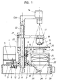
- Figure 1 is a schematic elevation view, partly in section, of the apparatus in which the intermediate arm is shown broken away to draw the attention to an irreal position of alignment thereof with the optical axis of the optical unit, which is impossible simultaneously with the alignment of the upper and lower arms.
- Figure 2 is partial schematic view, on a larger scale, of the manual operating device.
- the apparatus of the invention comprises a platform 1 and a column 2, a lower portion of which is supported in a fixed housing 3.
- the column may be actuated by a drive means comprising an electric motor 4, located above a support 5 and provided with a shaft 6 driving a drive pinion 7 which meshes with a ring gear situated externally of a rotary bushing 8, which is surrounded by the fixed housing 3.
- the column 2 is fixedly attached to a generally radially outwardly extending guide pin 9 which passes through, in the first place, a helical slot (not shown) formed in the rotary bushing and, in the second place, a generally inverted L-shaped slot 10.
- a guide pin 9 passes through, in the first place, a helical slot (not shown) formed in the rotary bushing and, in the second place, a generally inverted L-shaped slot 10.
- the shaft 6 is provided with a cam 11 engaging an optical switch 12 stopping the motor 4.
- a surrounding member 13 is supported on the fixed housing 3 and the upper portion thereof surrounds the column 2 and is extended to form the upper arm 13a which carried the video camera 14.
- the lower portion of the surrounding member 13 also surrounds the column 2 and supports a lower arm 16 in which there is mounted a semitransparent screen 15 situated vertically below the camera 14, with the distance therebetween being constant.
- the screen 15 is preferably provided with a mark corresponding with the centre thereof and a further mark showing an axis.
- an intermediate arm 17 which, as stated above, is angularly offset from the other two arms.
- the intermediate arm 17 carries a ball joint 18 for receiving a member 19, provided with adhesive means, to be referred to hereinafter.
- the said arm 17 is provided with a notch for a positioner 21 sliding in an elongate orifice 22 of the surrounding member 13.
- the optical unit constituted by a support 23, on which there is held, by means of a protective disc 24 and supports 25, an ophthalmic lens 26 to be centered and blocked.
- the optical unit comprises at least one condensing lens 27 and, at a lower level, a lamp 28, mounted on a bracket 29 and associated with a power control 30.
- the platform 1 also carries a device comprising a manual control 31 which, by way of a cam 32, actuates a rightangled lever 35 which rocks about the apex thereof. As it rocks, the lever 35 engages the stem 36 whereby the surrounding member 13 is axially moved.
- a manual control 31 which, by way of a cam 32, actuates a rightangled lever 35 which rocks about the apex thereof. As it rocks, the lever 35 engages the stem 36 whereby the surrounding member 13 is axially moved.
- the apparatus works as follows: initially a member 19 is mounted on the ball joint 18 of the intermediate arm 17. Furthermore, the ophthalmic lens 26 to be centered and blocked is mounted on the support means 25. The centre and axis marks of the screen 15 allow for appropriate mounting of the lens 26.
- the light-emitting source 28 is illuminated, whereby the condensing lenses 27 produce an image of the ophthalmic lens 26. By appropriately moving the screen 15, this picks up the image, which is picked up by the video camera 14. It should be noted that the video camera 14 picks up the plane image produced on the screen 15, whereby any error due to the direct viewing of the lens 26, the thickness of which may cause distorsion, is avoided.
- the image picked up by the camera 14 is transmitted to a not shown monitor which at the same time picks up the image of the frame ring to which the lens 26 is to be mounted, the latter image having been suitably moved depending on the required corrections, in the light of the wearer's and the frame's data. The superimpositioning of both images allows it to be checked whether the lens 26 is suitable for the chosen frame.
- the drive device causes angular movement of the upper and lower arms 13a and 16, respectively, and at the same time an equal angular movement of the intermediate arm 17, whereby the ball joint 18 and the member 19 are aligned with the optical axis of the optical unit.
- Lowering of the column 2 causes a lowering of the intermediate arm 17, until the member 19 is adhered to the ophthalmic lens 26, precisely on the geometric and optical centre thereof.
- Operation is initiated with the actuation of a microswitch 33 and is controlled by an electronic card 34, which also causes reverse movement of the arms 13a, 16 and 17, leaving the machine ready for receiving a new ophthalmic lens.
- the lens 26 receives the blocking member 19 on the centre thereof, whereby during the subsequent bevelling process, the ophthalmic lens rotates in a fully satisfactory way.
Landscapes
- Engineering & Computer Science (AREA)
- Mechanical Engineering (AREA)
- Chemical & Material Sciences (AREA)
- Ceramic Engineering (AREA)
- Inorganic Chemistry (AREA)
- Eyeglasses (AREA)
- Eye Examination Apparatus (AREA)
- Grinding And Polishing Of Tertiary Curved Surfaces And Surfaces With Complex Shapes (AREA)
- Testing Of Optical Devices Or Fibers (AREA)
- Accessories Of Cameras (AREA)
Claims (7)
- Vorrichtung zum Zentrieren und Blockieren von Brillengläsern zum Gebrauch in Linsen-Facettiermaschinen, wobei die genannte Vorrichtung versehen ist mit: einer Trägereinrichtung (25) für das Brillenglas (26), einer Einrichtung (17), um ein Element (19) an dem genannten Brillenglas (26) haftend zu befestigen, einem Monitor, der ein digitales Bild der Kontur der durch schräges Abschneiden zu erhaltenden Form aufnimmt, und einer Videokamera (14), die vertikal über dem genannten Brillenglas (26) angeordnet ist, Bilder aufnimmt, und sie zu dem genannten Monitor überträgt, dadurch gekennzeichnet, daß sie umfaßt: a) eine optische Einheit (27, 28) mit wenigstens einer Kollektivlinse (27) und nahe bei einer Lichtquelle (28), wobei die genannte Einheit niedriger als die genannte Trägereinrichtung (25) sitzt und eine optische Achse definiert, und b) einen wenigstens teilweise lichtdurchlassigen Schirm (15), der angepaßt ist, um mit seiner Mitte mit der genannten optischen Achse ausgerichtet angeordnet zu sein, der zwischen der genannten Videokamera (14) und der genannten Trägereinrichtung (25) eingesetzt ist und ein von der optischen Einheit (27,28) projiziertes Bild des auf der genannten Trägereinrichtung (25) angeordneten Brillenglases (26) aufnehmen kann, und dadurch, daß der Abstand zwischen der Videokamera (14) und dem lichtdurchlassigen Schirm (15) konstant ist.
- Vorrichtung nach Anspruch 1, dadurch gekennzeichnet, daß der genannte lichtdurchlässige Schirm (15) in Richtung der genannten optischen Achse entsprechend bewegbar ist, um das von der optischen Einheit (27, 28) projizierte Bild des Brillenglases (26) aufzunehmen.
- Vorrichtung nach Anspruch 1 oder 2, dadurch gekennzeichnet, daß sie mit einer Säule (2) versehen ist, die sich drehen und axial bewegen kann, und die Säule (2) an ihrem oberen Ende mit einem umgebenden Element (13) verbunden ist, das mit einem oberen Arm (13a), der die Videokamera (14) trägt, und einem unteren Arm (16) versehen ist, der den lichtdurchlässigen Schirm (15) trägt, wobei das genannte umgebende Element (13) unabhängig von der Säule (2) vertikal bewegbar ist.
- Vorrichtung nach Anspruch 3, dadurch gekennzeichnet, daß die unabhängige vertikale Bewegung des umgebenden Elements (13) von einer Steuerung (31) bewirkt wird, die eine Drehung einer Nocke (32) bewirkt, so daß die Drehung der genannten Nocke (32) angepaßt ist, um einen Mikroschalter (33) zu betätigen, um den Betriebszyklus der Vorrichtung zu starten.
- Vorrichtung nach Anspruch 3, dadurch gekennzeichnet, daß die Säule (2) mit einem Zwischenarm (17) versehen ist, der ein an dem Brillenglas haftend zu befestigendes Element (19) trägt, wobei der genannte Arm (17) um einen Winkel gegenüber dem genannten oberen (13a) und unteren (16) Arm versetzt ist.
- Vorrichtung nach einem der Ansprüche 3 bis 5, dadurch gekennzeichnet, daß ein unterer Abschnitt der Säule (2) von einer sich drehenden Buchse (8) umgeben ist, die mit einem schraubenförmigen Schlitz und einem äußeren Tellerrad versehen ist, das in ein von einem Motor (4) angetriebenes Antriebsritzel (7) eingreift, wobei die sich drehende Buchse (8) wiederum von einem festen Gehäuse (3) umgeben ist, das mit einem umgekehrt L-förmigen Schlitz (10) versehen ist, wobei ein Führungsbolzen (9) fest an der Säule (2) angebracht ist, der durch die genannten Schlitze hindurchgeht, so daß eine Drehung der Buchse (8) bewirkt: a) eine vertikale Bewegung der Säule (2), während sich der Führungsbolzen (9) in dem schraubenförmigen Schlitz und dem vertikalen Schenkel des umgekehrt L-förmigen Schlitzes (10) befindet, und b) eine Drehung der Säule (2), wenn sich der Führungsbolzen (9) in dem schraubenförmigen Schlitz und dem im allgemeinen horizontalen Schenkel des umgekehrt L-förmigen Schlitzes (10) befindet.
- Vorrichtung nach Anspruch 6, dadurch gekennzeichnet, daß das Antriebsritzel (7) eine Nocke (11) trägt, welche einen optischen Schalter (12) schaltet, der den Motor (4) ausschaltet.
Applications Claiming Priority (2)
| Application Number | Priority Date | Filing Date | Title |
|---|---|---|---|
| ES8902510 | 1989-07-17 | ||
| ES8902510A ES2014801A6 (es) | 1989-07-17 | 1989-07-17 | Aparato para el centrado y bloqueado de lentes oftalmologicas> |
Publications (2)
| Publication Number | Publication Date |
|---|---|
| EP0409760A1 EP0409760A1 (de) | 1991-01-23 |
| EP0409760B1 true EP0409760B1 (de) | 1993-12-01 |
Family
ID=8263111
Family Applications (1)
| Application Number | Title | Priority Date | Filing Date |
|---|---|---|---|
| EP19900500068 Revoked EP0409760B1 (de) | 1989-07-17 | 1990-07-16 | Vorrichtung zum Zentrieren und Festhalten von Brillengläsern |
Country Status (3)
| Country | Link |
|---|---|
| EP (1) | EP0409760B1 (de) |
| DE (1) | DE69004881T2 (de) |
| ES (2) | ES2014801A6 (de) |
Families Citing this family (20)
| Publication number | Priority date | Publication date | Assignee | Title |
|---|---|---|---|---|
| US5425665A (en) * | 1992-12-09 | 1995-06-20 | National Optronics, Inc. | Optical lens blocker and method |
| US5505654A (en) * | 1993-09-07 | 1996-04-09 | Gerber Optical, Inc. | Lens blocking apparatus |
| DE19505524C2 (de) * | 1995-02-18 | 1996-12-19 | Wernicke & Co Gmbh | Vorrichtung zum Zentrieren eines Brillenglasrohlings und Anbringen eines Halteteils auf einer optischen Oberfläche des Brillenglasrohlings |
| US5721644A (en) * | 1996-09-24 | 1998-02-24 | Gerber Optical, Inc. | Apparatus and method for attaching a finishing block to a lens |
| ES2136541B1 (es) * | 1997-05-06 | 2000-08-01 | Indo Int Sa | Aparato para el centrado y bloqueo de un disco de lente oftalmica. |
| US6798501B1 (en) | 1998-01-30 | 2004-09-28 | Nidek Co., Ltd. | Cup attaching apparatus |
| DE69920542T3 (de) * | 1998-01-30 | 2012-05-24 | Nidek Co., Ltd. | Vorrichtung zum Anbringen eines Halteteils |
| JP3929595B2 (ja) * | 1998-03-31 | 2007-06-13 | 株式会社ニデック | 眼鏡レンズ加工システム |
| FR2794045B1 (fr) * | 1999-05-27 | 2001-08-10 | Briot Int | Dispositif de centrage et de positionnement d'une ebauche de verre de lunettes |
| JP3828686B2 (ja) | 1999-08-31 | 2006-10-04 | 株式会社ニデック | カップ取付装置 |
| US6283825B1 (en) * | 1999-12-21 | 2001-09-04 | Johnson & Johnson Vision Products, Inc. | Automatic trimmer machine |
| JP3842953B2 (ja) | 2000-04-28 | 2006-11-08 | 株式会社ニデック | カップ取付け装置 |
| JP3966696B2 (ja) | 2001-03-26 | 2007-08-29 | 株式会社ニデック | カップ取付け装置 |
| FR2866721B1 (fr) * | 2004-02-24 | 2006-05-19 | Essilor Int | Methode de centrage manuel d'une lentille ophtalmique de lunettes avec affichage intermittent d'un signe opaque servant a la correction de l'erreur de deviation prismatique induite par la lentille |
| FR2866718B1 (fr) * | 2004-02-24 | 2006-05-05 | Essilor Int | Dispositif centreur-bloqueur d'une lentille ophtalmique de lunettes, methode de detection automatique et methodes de centrage manuel associees |
| FR2866719B1 (fr) * | 2004-02-24 | 2006-05-19 | Essilor Int | Methode de contrage manuel d'une lentille ophtalmique de lunettes dans un centreur-bloqueur et dispositif centreur-bloqueur associe |
| ES2257978B1 (es) * | 2006-03-09 | 2007-05-01 | Indo Internacional S.A. | Equipo de captura de contorno, marcas, taladros, fresados y grabados de una lente oftalmica o de un talco para gafas. |
| JP5348849B2 (ja) | 2007-03-30 | 2013-11-20 | 株式会社ニデック | カップ取付け装置 |
| FR3022641B1 (fr) * | 2014-06-23 | 2016-07-01 | Essilor Int | Appareil centreur-bloqueur pour lentille ophtalmique |
| KR101996227B1 (ko) * | 2017-11-29 | 2019-10-01 | 주식회사 휴비츠 | 렌즈 블록커 |
Family Cites Families (4)
| Publication number | Priority date | Publication date | Assignee | Title |
|---|---|---|---|---|
| FR2151202A5 (de) * | 1971-08-25 | 1973-04-13 | Lunetiers | |
| GB1559035A (en) * | 1976-10-23 | 1980-01-09 | Proptic | Apparatus for the preparation of eye glass lenses prior tothe shaping and/or bevelling thereof |
| DE2713168C3 (de) * | 1977-03-25 | 1979-09-20 | Wernicke & Co Gmbh, 4000 Duesseldorf | Einrichtung zum dezentrierten Befestigen eines Halters an einer Brillenglaslinse |
| FR2582975B1 (fr) * | 1985-06-10 | 1987-08-28 | Briot Int | Appareil pour centrer et poser un adaptateur sur une ebauche de verre optique et pour commander une rectifieuse |
-
1989
- 1989-07-17 ES ES8902510A patent/ES2014801A6/es not_active Expired - Lifetime
-
1990
- 1990-07-16 ES ES90500068T patent/ES2047299T3/es not_active Expired - Lifetime
- 1990-07-16 DE DE1990604881 patent/DE69004881T2/de not_active Revoked
- 1990-07-16 EP EP19900500068 patent/EP0409760B1/de not_active Revoked
Also Published As
| Publication number | Publication date |
|---|---|
| ES2014801A6 (es) | 1990-07-16 |
| ES2047299T3 (es) | 1994-02-16 |
| EP0409760A1 (de) | 1991-01-23 |
| DE69004881D1 (de) | 1994-01-13 |
| DE69004881T2 (de) | 1994-05-05 |
Similar Documents
| Publication | Publication Date | Title |
|---|---|---|
| EP0409760A1 (de) | Vorrichtung zum Zentrieren und Festhalten von Brillengläsern | |
| JP3778707B2 (ja) | 眼鏡レンズ加工装置 | |
| EP0947287B1 (de) | Brillenglasbearbeitungssystem und System zur Vorbereitung der Brillenglasbearbeitung | |
| US5498200A (en) | Device for parallex-free centering of a blank for a glass lens for spectacles and for providing markings and/or attaching a holder before inserting the blank into a grinding machine for blanks for glass lenses | |
| GB2183184A (en) | Lens grinding machine | |
| JP4068233B2 (ja) | カップ取付装置 | |
| US6481095B1 (en) | Cup attaching apparatus | |
| EP0978352B1 (de) | Brillenglasgestaltungs-Eingabesystem | |
| KR101126303B1 (ko) | 안경렌즈를 수동으로 중심조정하는 방법, 안경렌즈의 중심조정 및 블로킹 방법, 및 중심조정 및 블로킹 장치 | |
| JP3842953B2 (ja) | カップ取付け装置 | |
| JP2001277086A (ja) | レンズ周縁加工装置 | |
| US5720647A (en) | Device for mounting a retaining part on an optical surface of an ophthalmic blank | |
| US4372368A (en) | Blocking apparatus for fixing a metal block to the finished face of a semi-finished spectacle lens blank | |
| US6798501B1 (en) | Cup attaching apparatus | |
| EP0933163B2 (de) | Vorrichtung zum Anbringen eines Halteteils | |
| JPH11216650A (ja) | 軸出装置 | |
| EP0371967A1 (de) | Gerät zum abtasten einer unbearbeiteten linse und eine maschine mit einem solchen gerät. | |
| JPH10277901A (ja) | レンズ研削加工装置 | |
| US6298277B1 (en) | System for making an optical glass from a blank | |
| JP3953960B2 (ja) | 被加工レンズの挟持方法及びその装置 | |
| US4438602A (en) | Lens carrier assembly for automatic lens blocking | |
| US20230031187A1 (en) | Device and method for mounting leap block | |
| JPS6240761Y2 (de) | ||
| JPH09183053A (ja) | レンズ研削方法及びそのための装置 | |
| JPH08297262A (ja) | 眼鏡レンズの位置合わせ方法及びその装置 |
Legal Events
| Date | Code | Title | Description |
|---|---|---|---|
| PUAI | Public reference made under article 153(3) epc to a published international application that has entered the european phase |
Free format text: ORIGINAL CODE: 0009012 |
|
| AK | Designated contracting states |
Kind code of ref document: A1 Designated state(s): BE DE ES FR GB IT |
|
| 17P | Request for examination filed |
Effective date: 19910523 |
|
| 17Q | First examination report despatched |
Effective date: 19921119 |
|
| GRAA | (expected) grant |
Free format text: ORIGINAL CODE: 0009210 |
|
| AK | Designated contracting states |
Kind code of ref document: B1 Designated state(s): BE DE ES FR GB IT |
|
| REF | Corresponds to: |
Ref document number: 69004881 Country of ref document: DE Date of ref document: 19940113 |
|
| ITF | It: translation for a ep patent filed | ||
| REG | Reference to a national code |
Ref country code: ES Ref legal event code: FG2A Ref document number: 2047299 Country of ref document: ES Kind code of ref document: T3 |
|
| ET | Fr: translation filed | ||
| PLBI | Opposition filed |
Free format text: ORIGINAL CODE: 0009260 |
|
| 26 | Opposition filed |
Opponent name: WERNICKE & CO. GMBH Effective date: 19940829 |
|
| PGFP | Annual fee paid to national office [announced via postgrant information from national office to epo] |
Ref country code: ES Payment date: 19950609 Year of fee payment: 6 |
|
| PGFP | Annual fee paid to national office [announced via postgrant information from national office to epo] |
Ref country code: GB Payment date: 19950628 Year of fee payment: 6 |
|
| PGFP | Annual fee paid to national office [announced via postgrant information from national office to epo] |
Ref country code: FR Payment date: 19950629 Year of fee payment: 6 |
|
| PGFP | Annual fee paid to national office [announced via postgrant information from national office to epo] |
Ref country code: BE Payment date: 19950712 Year of fee payment: 6 |
|
| PGFP | Annual fee paid to national office [announced via postgrant information from national office to epo] |
Ref country code: DE Payment date: 19950719 Year of fee payment: 6 |
|
| RDAG | Patent revoked |
Free format text: ORIGINAL CODE: 0009271 |
|
| STAA | Information on the status of an ep patent application or granted ep patent |
Free format text: STATUS: PATENT REVOKED |
|
| 27W | Patent revoked |
Effective date: 19950710 |
|
| GBPR | Gb: patent revoked under art. 102 of the ep convention designating the uk as contracting state |
Free format text: 950710 |