EP0409722A1 - Vorrichtungen zur Fixierung eines Elementes an einer perforierten, einseitig zugänglichen Unterlage - Google Patents
Vorrichtungen zur Fixierung eines Elementes an einer perforierten, einseitig zugänglichen Unterlage Download PDFInfo
- Publication number
- EP0409722A1 EP0409722A1 EP90402057A EP90402057A EP0409722A1 EP 0409722 A1 EP0409722 A1 EP 0409722A1 EP 90402057 A EP90402057 A EP 90402057A EP 90402057 A EP90402057 A EP 90402057A EP 0409722 A1 EP0409722 A1 EP 0409722A1
- Authority
- EP
- European Patent Office
- Prior art keywords
- rod
- foot
- support
- head
- nut
- Prior art date
- Legal status (The legal status is an assumption and is not a legal conclusion. Google has not performed a legal analysis and makes no representation as to the accuracy of the status listed.)
- Granted
Links
Images

Classifications
-
- F—MECHANICAL ENGINEERING; LIGHTING; HEATING; WEAPONS; BLASTING
- F16—ENGINEERING ELEMENTS AND UNITS; GENERAL MEASURES FOR PRODUCING AND MAINTAINING EFFECTIVE FUNCTIONING OF MACHINES OR INSTALLATIONS; THERMAL INSULATION IN GENERAL
- F16B—DEVICES FOR FASTENING OR SECURING CONSTRUCTIONAL ELEMENTS OR MACHINE PARTS TOGETHER, e.g. NAILS, BOLTS, CIRCLIPS, CLAMPS, CLIPS OR WEDGES; JOINTS OR JOINTING
- F16B39/00—Locking of screws, bolts or nuts
- F16B39/22—Locking of screws, bolts or nuts in which the locking takes place during screwing down or tightening
-
- F—MECHANICAL ENGINEERING; LIGHTING; HEATING; WEAPONS; BLASTING
- F16—ENGINEERING ELEMENTS AND UNITS; GENERAL MEASURES FOR PRODUCING AND MAINTAINING EFFECTIVE FUNCTIONING OF MACHINES OR INSTALLATIONS; THERMAL INSULATION IN GENERAL
- F16B—DEVICES FOR FASTENING OR SECURING CONSTRUCTIONAL ELEMENTS OR MACHINE PARTS TOGETHER, e.g. NAILS, BOLTS, CIRCLIPS, CLAMPS, CLIPS OR WEDGES; JOINTS OR JOINTING
- F16B13/00—Dowels or other devices fastened in walls or the like by inserting them in holes made therein for that purpose
- F16B13/04—Dowels or other devices fastened in walls or the like by inserting them in holes made therein for that purpose with parts gripping in the hole or behind the reverse side of the wall after inserting from the front
- F16B13/08—Dowels or other devices fastened in walls or the like by inserting them in holes made therein for that purpose with parts gripping in the hole or behind the reverse side of the wall after inserting from the front with separate or non-separate gripping parts moved into their final position in relation to the body of the device without further manual operation
- F16B13/0808—Dowels or other devices fastened in walls or the like by inserting them in holes made therein for that purpose with parts gripping in the hole or behind the reverse side of the wall after inserting from the front with separate or non-separate gripping parts moved into their final position in relation to the body of the device without further manual operation by a toggle-mechanism
Definitions
- the invention relates to devices for fixing an element on a perforated support accessible from one side only and in particular on a sheet metal forming part of a box closed at least in part, as it frequently happens in vehicle bodies.
- a rod terminated at one end by a foot intended to be introduced into two aligned holes made respectively in the support and in the element to be fixed, this foot being arranged so as to flourish transversely just after its crossing of the two holes and then to take support on the support during the exercise on the rod of a traction in opposite direction to the above introduction, - And on the other hand, a head capable of being fixed on the end of the rod, opposite its foot, by resting on the element to be fixed so that this element is clamped against the support, between head and foot.
- the head is a notched ring surrounding the rod, axially movable along this rod and adapted to cooperate with a rectilinear series of notches provided on said rod.
- the object of the invention is, above all, to eliminate these drawbacks.
- the fasteners of the kind in question according to the invention are essentially characterized in that their rod is delimited externally by a threaded cylindrical surface hollowed out by longitudinal grooves having a profile with oblique ramp and radial bearing, in that their head is constituted by a nut capable of cooperating by screwing with the thread of the rod, nut extended axially by a skirt on the internal face of which protruding notches capable of cooperating with the grooves of the rod for the purpose of angular locking of the nut on this rod and in that the end of the rod opposite the foot is notched so as to be able to be locked angularly by a screwdriver or similar tool.
- the rod is hollowed out axially so as to form a cylindrical sleeve open axially on the side of its notched end
- the notches hollowed out in the end edge of the sleeve each include a longitudinal edge and an oblique edge, - the number of grooves is equal to four and that of the notches is equal to five.
- the invention includes, apart from these main provisions, certain other provisions which are preferably used at the same time and which will be more explicitly discussed below.
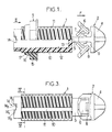
- the fixing device considered is composed of two parts made of a molded plastic, namely, on the one hand, a rod 1 terminated by a foot 2 and, on the other hand, a head 3.
- the foot 2 itself comprises a terminal tip 4 of pointed shape connected to the rest of the rod 1 by a thinner core 5.
- Two legs 6 are connected to the core 5 by flexible bridges 7 and have heels 8 complementary to cells 9 hollowed out in the end piece 4.
- these legs 6 and their mounting are such: - that, during the introduction of the foot 2 according to arrow F in a complementary hole (not shown) hollowed out in a support sheet, they are automatically retracted towards the axis of the device by bending the bridges 7, - that, just after crossing said hole, they deploy elastically, - and that, during the subsequent exercise on the rod 1 of a traction oriented in the opposite direction to the arrow F, the application of these lugs against the edges of the through hole has the effect of orienting said lugs transversely, by housing their heels 8 in the cells 9, which axially locks the device by preventing its extraction from the hole in said opposite direction of the arrow F.
- rod 1 As regards the rod 1, it is delimited here externally by a threaded cylindrical surface 10 hollowed out by longitudinal grooves 11.
- a hole 12 is axially hollowed out in the body constituting the rod 1, which body thus forms a cylindrical sleeve.
- This sleeve has at one of its axial ends a bottom 13 extended by the core 5 above and it is open at its other axial end.
- Notches 14 are hollowed axially in the edge of its opening to allow its angular blocking using a screwdriver or similar tool.
- the profile of these notches comprising a longitudinal edge 141 and an oblique edge 142, facilitates the positioning of said tool.
- the head 3 it is constituted by a nut 15 suitable for cooperating by screwing with the threaded surface 10 of the rod 1, nut extended axially by a skirt 16.
- this skirt 16 projects radially at least one notch 17 capable of interacting with the grooves 11 for the purpose of angular blocking of the head 3 on the rod 1.
- the profiles, numbers and locations of the grooves 11 and / or those of the notches 17 are provided in such a way that, on the one hand, the angular blocking of the head on the rod is irreversible and that, on the other hand, this blocking can be obtained for a plurality of relative angular positions close to the head relative to the rod.
- the surfaces delimiting the grooves 11 and the notches 17 include: a flat ramp (18, fig. 4; 19, fig. 5) inclined relative to the corresponding cylindrical surface (respectively threaded surface 10 internal surface of the skirt 16), ramp of which an angular end is located on said surface, - And a radial planar bearing (20; 21) connecting to said surface the other angular end of said ramp (18 19).
- the second advantage is obtained by providing a plurality of grooves 11 and a plurality of notches 17, by regularly distributing these grooves and notches around the axis of the device and by giving different values to the number of grooves and to that of the notches.
- the above angular deviation is equal to only 18 °.
- the assembly is then completed with a very effective clamping of the element against its support, between the head and the foot of the device, and this without the need for any welding operation.
Landscapes
- Engineering & Computer Science (AREA)
- General Engineering & Computer Science (AREA)
- Mechanical Engineering (AREA)
- Dowels (AREA)
- Fishing Rods (AREA)
- Surgical Instruments (AREA)
- Mutual Connection Of Rods And Tubes (AREA)
- Snaps, Bayonet Connections, Set Pins, And Snap Rings (AREA)
Applications Claiming Priority (2)
| Application Number | Priority Date | Filing Date | Title |
|---|---|---|---|
| FR8909783 | 1989-07-20 | ||
| FR8909783A FR2650038B1 (fr) | 1989-07-20 | 1989-07-20 | Perfectionnements aux dispositifs pour fixer un element sur un support perfore accessible d'un seul cote |
Publications (2)
| Publication Number | Publication Date |
|---|---|
| EP0409722A1 true EP0409722A1 (de) | 1991-01-23 |
| EP0409722B1 EP0409722B1 (de) | 1992-12-02 |
Family
ID=9383972
Family Applications (1)
| Application Number | Title | Priority Date | Filing Date |
|---|---|---|---|
| EP19900402057 Expired - Lifetime EP0409722B1 (de) | 1989-07-20 | 1990-07-17 | Vorrichtungen zur Fixierung eines Elementes an einer perforierten, einseitig zugänglichen Unterlage |
Country Status (4)
| Country | Link |
|---|---|
| EP (1) | EP0409722B1 (de) |
| DE (1) | DE69000526T2 (de) |
| ES (1) | ES2035727T3 (de) |
| FR (1) | FR2650038B1 (de) |
Cited By (2)
| Publication number | Priority date | Publication date | Assignee | Title |
|---|---|---|---|---|
| CN108661997A (zh) * | 2018-07-24 | 2018-10-16 | 海盐哈特惠机械五金制品有限公司 | 一种可重复拆装的单边螺栓紧固件 |
| CN113187797A (zh) * | 2021-05-24 | 2021-07-30 | 鲁东大学 | 一种用于输电线路杆塔及电力金具的可靠防松螺母 |
Citations (5)
| Publication number | Priority date | Publication date | Assignee | Title |
|---|---|---|---|---|
| FR440728A (fr) * | 1912-02-21 | 1912-07-19 | Charles Arthur Thompson | Perfectionnements aux écrous indesserrables |
| US1467907A (en) * | 1922-04-15 | 1923-09-11 | Miyagi Takeo | Nut lock |
| US1942259A (en) * | 1932-03-04 | 1934-01-02 | Schiemer George | Combination lock bolt |
| US3722037A (en) * | 1971-08-23 | 1973-03-27 | Illinois Tool Works | Locating plug |
| DE3427640A1 (de) * | 1984-07-26 | 1986-02-06 | Bayerische Motoren Werke AG, 8000 München | Schraube |
-
1989
- 1989-07-20 FR FR8909783A patent/FR2650038B1/fr not_active Expired - Fee Related
-
1990
- 1990-07-17 DE DE1990600526 patent/DE69000526T2/de not_active Expired - Fee Related
- 1990-07-17 ES ES90402057T patent/ES2035727T3/es not_active Expired - Lifetime
- 1990-07-17 EP EP19900402057 patent/EP0409722B1/de not_active Expired - Lifetime
Patent Citations (5)
| Publication number | Priority date | Publication date | Assignee | Title |
|---|---|---|---|---|
| FR440728A (fr) * | 1912-02-21 | 1912-07-19 | Charles Arthur Thompson | Perfectionnements aux écrous indesserrables |
| US1467907A (en) * | 1922-04-15 | 1923-09-11 | Miyagi Takeo | Nut lock |
| US1942259A (en) * | 1932-03-04 | 1934-01-02 | Schiemer George | Combination lock bolt |
| US3722037A (en) * | 1971-08-23 | 1973-03-27 | Illinois Tool Works | Locating plug |
| DE3427640A1 (de) * | 1984-07-26 | 1986-02-06 | Bayerische Motoren Werke AG, 8000 München | Schraube |
Cited By (3)
| Publication number | Priority date | Publication date | Assignee | Title |
|---|---|---|---|---|
| CN108661997A (zh) * | 2018-07-24 | 2018-10-16 | 海盐哈特惠机械五金制品有限公司 | 一种可重复拆装的单边螺栓紧固件 |
| CN108661997B (zh) * | 2018-07-24 | 2023-08-15 | 浙江哈特惠科技股份有限公司 | 一种可重复拆装的单边螺栓紧固件 |
| CN113187797A (zh) * | 2021-05-24 | 2021-07-30 | 鲁东大学 | 一种用于输电线路杆塔及电力金具的可靠防松螺母 |
Also Published As
| Publication number | Publication date |
|---|---|
| DE69000526D1 (de) | 1993-01-14 |
| EP0409722B1 (de) | 1992-12-02 |
| FR2650038A1 (fr) | 1991-01-25 |
| ES2035727T3 (es) | 1993-04-16 |
| FR2650038B1 (fr) | 1991-11-08 |
| DE69000526T2 (de) | 1993-04-08 |
Similar Documents
| Publication | Publication Date | Title |
|---|---|---|
| EP0511891B1 (de) | Verbindungselement zur Schnellkupplung eines Rohres | |
| FR2495244A1 (fr) | Perfectionnements aux dispositifs pour fixer des objets sur des toles accessibles d'un seul cote | |
| FR2718822A1 (fr) | Accouplement emboîtable à désaccouplement simplifié, pour relier deux conduits de circulation d'un fluide. | |
| FR2776345A1 (fr) | Dispositif a monter en aveugle | |
| FR2716244A1 (fr) | Rivet en matière plastique pour fixer une pièce en forme de plaque à un support à surface sensiblement plane. | |
| FR2763368A1 (fr) | Rivet en matiere plastique | |
| FR3014531A1 (fr) | Dispositif de fixation pour cable | |
| FR2624569A1 (fr) | Attache a retenue pour elements de construction | |
| FR2636382A1 (fr) | Ensemble d'element de fixation et d'anneau de retenue | |
| FR2633347A1 (fr) | Dispositif de fixation auto-bloquant | |
| FR2754576A1 (fr) | Ecrou a montage par clippage sur un profile | |
| FR2618190A1 (fr) | Ensemble a organe de fixation a action rapide et cheville a tete lisse. | |
| FR2458624A1 (fr) | Piece d'extremite, de raccordement ou de liaison pour elements souples tels que cables, fils ou autres elements | |
| EP0409722B1 (de) | Vorrichtungen zur Fixierung eines Elementes an einer perforierten, einseitig zugänglichen Unterlage | |
| EP1471269A2 (de) | Vorrichtung zur Verriegelung einer Mutter auf einem Gewinde zur Verbindung eines Werkstücks durch Festschrauben der Mutter an ein anderes mit diesem Gewinde solidarischem Werkstück | |
| FR2601089A1 (fr) | Ecrou expansible en matiere plastique, resistant a l'endommagement et vis adaptee a celui-ci | |
| EP1926192B1 (de) | Gehäuse für Trennwand in Trockenbauweise, mit axial fixierten Laschen und axial verschiebbaren Außenstützen | |
| FR2467485A1 (fr) | Lampe electrique comportant un culot en forme de douille | |
| FR2821886A1 (fr) | Echelle, notamment echelle de piscine | |
| FR2492015A1 (fr) | Perfectionnement aux attaches en matiere plastique pour assurer une fixation sur le bord d'une plaque | |
| EP0626533B1 (de) | Halteschelle auf einer Stütze für ein Rohr oder dergleichen | |
| FR2566848A1 (fr) | Dispositif pour la fixation d'une manchette sur une ouverture d'une paroi quelconque d'epaisseur variable | |
| EP0077695B1 (de) | Befestigungselement mit Mutternhalterung | |
| EP2372171B1 (de) | Befestigungseinheit | |
| FR2534986A1 (fr) | Procede et attache de fixation de deux pieces juxtaposables |
Legal Events
| Date | Code | Title | Description |
|---|---|---|---|
| PUAI | Public reference made under article 153(3) epc to a published international application that has entered the european phase |
Free format text: ORIGINAL CODE: 0009012 |
|
| AK | Designated contracting states |
Kind code of ref document: A1 Designated state(s): DE ES IT |
|
| 17P | Request for examination filed |
Effective date: 19910302 |
|
| 17Q | First examination report despatched |
Effective date: 19920331 |
|
| GRAA | (expected) grant |
Free format text: ORIGINAL CODE: 0009210 |
|
| AK | Designated contracting states |
Kind code of ref document: B1 Designated state(s): DE ES IT |
|
| ITF | It: translation for a ep patent filed | ||
| REF | Corresponds to: |
Ref document number: 69000526 Country of ref document: DE Date of ref document: 19930114 |
|
| PLBE | No opposition filed within time limit |
Free format text: ORIGINAL CODE: 0009261 |
|
| STAA | Information on the status of an ep patent application or granted ep patent |
Free format text: STATUS: NO OPPOSITION FILED WITHIN TIME LIMIT |
|
| 26N | No opposition filed | ||
| REG | Reference to a national code |
Ref country code: ES Ref legal event code: PC2A Owner name: COMPAGNIE DE MATERIEL ET D'EQUIPEMENTS TECHNIQUES- |
|
| PGFP | Annual fee paid to national office [announced via postgrant information from national office to epo] |
Ref country code: ES Payment date: 19970701 Year of fee payment: 8 |
|
| PGFP | Annual fee paid to national office [announced via postgrant information from national office to epo] |
Ref country code: DE Payment date: 19970731 Year of fee payment: 8 |
|
| PG25 | Lapsed in a contracting state [announced via postgrant information from national office to epo] |
Ref country code: ES Free format text: LAPSE BECAUSE OF THE APPLICANT RENOUNCES Effective date: 19980718 |
|
| PG25 | Lapsed in a contracting state [announced via postgrant information from national office to epo] |
Ref country code: DE Free format text: LAPSE BECAUSE OF NON-PAYMENT OF DUE FEES Effective date: 19990501 |
|
| REG | Reference to a national code |
Ref country code: ES Ref legal event code: FD2A Effective date: 20001009 |
|
| PG25 | Lapsed in a contracting state [announced via postgrant information from national office to epo] |
Ref country code: IT Free format text: LAPSE BECAUSE OF NON-PAYMENT OF DUE FEES Effective date: 20050717 |