EP0408876A1 - Steuerung und Erweiterung des Wirkungbereiches eines überhitzten Innenverbrennungsmotors - Google Patents
Steuerung und Erweiterung des Wirkungbereiches eines überhitzten Innenverbrennungsmotors Download PDFInfo
- Publication number
- EP0408876A1 EP0408876A1 EP90110395A EP90110395A EP0408876A1 EP 0408876 A1 EP0408876 A1 EP 0408876A1 EP 90110395 A EP90110395 A EP 90110395A EP 90110395 A EP90110395 A EP 90110395A EP 0408876 A1 EP0408876 A1 EP 0408876A1
- Authority
- EP
- European Patent Office
- Prior art keywords
- engine
- load signal
- engine load
- values
- causing
- Prior art date
- Legal status (The legal status is an assumption and is not a legal conclusion. Google has not performed a legal analysis and makes no representation as to the accuracy of the status listed.)
- Granted
Links
- 238000013021 overheating Methods 0.000 claims abstract description 6
- 230000007246 mechanism Effects 0.000 claims description 6
- 238000002485 combustion reaction Methods 0.000 claims description 4
- 239000002826 coolant Substances 0.000 abstract description 10
- 230000009467 reduction Effects 0.000 description 5
- 238000001816 cooling Methods 0.000 description 4
- 238000010586 diagram Methods 0.000 description 4
- 230000008901 benefit Effects 0.000 description 2
- 239000002184 metal Substances 0.000 description 2
- 238000010276 construction Methods 0.000 description 1
- 230000001066 destructive effect Effects 0.000 description 1
- 230000008030 elimination Effects 0.000 description 1
- 238000003379 elimination reaction Methods 0.000 description 1
- 239000000446 fuel Substances 0.000 description 1
- 231100001261 hazardous Toxicity 0.000 description 1
- 239000007788 liquid Substances 0.000 description 1
- 239000000463 material Substances 0.000 description 1
- 230000008520 organization Effects 0.000 description 1
- 208000024891 symptom Diseases 0.000 description 1
Images
Classifications
-
- F—MECHANICAL ENGINEERING; LIGHTING; HEATING; WEAPONS; BLASTING
- F02—COMBUSTION ENGINES; HOT-GAS OR COMBUSTION-PRODUCT ENGINE PLANTS
- F02P—IGNITION, OTHER THAN COMPRESSION IGNITION, FOR INTERNAL-COMBUSTION ENGINES; TESTING OF IGNITION TIMING IN COMPRESSION-IGNITION ENGINES
- F02P5/00—Advancing or retarding ignition; Control therefor
- F02P5/04—Advancing or retarding ignition; Control therefor automatically, as a function of the working conditions of the engine or vehicle or of the atmospheric conditions
- F02P5/145—Advancing or retarding ignition; Control therefor automatically, as a function of the working conditions of the engine or vehicle or of the atmospheric conditions using electrical means
- F02P5/15—Digital data processing
- F02P5/1502—Digital data processing using one central computing unit
- F02P5/1504—Digital data processing using one central computing unit with particular means during a transient phase, e.g. acceleration, deceleration, gear change
-
- F—MECHANICAL ENGINEERING; LIGHTING; HEATING; WEAPONS; BLASTING
- F02—COMBUSTION ENGINES; HOT-GAS OR COMBUSTION-PRODUCT ENGINE PLANTS
- F02D—CONTROLLING COMBUSTION ENGINES
- F02D41/00—Electrical control of supply of combustible mixture or its constituents
- F02D41/22—Safety or indicating devices for abnormal conditions
-
- F—MECHANICAL ENGINEERING; LIGHTING; HEATING; WEAPONS; BLASTING
- F02—COMBUSTION ENGINES; HOT-GAS OR COMBUSTION-PRODUCT ENGINE PLANTS
- F02P—IGNITION, OTHER THAN COMPRESSION IGNITION, FOR INTERNAL-COMBUSTION ENGINES; TESTING OF IGNITION TIMING IN COMPRESSION-IGNITION ENGINES
- F02P11/00—Safety means for electric spark ignition, not otherwise provided for
- F02P11/02—Preventing damage to engines or engine-driven gearing
-
- F—MECHANICAL ENGINEERING; LIGHTING; HEATING; WEAPONS; BLASTING
- F05—INDEXING SCHEMES RELATING TO ENGINES OR PUMPS IN VARIOUS SUBCLASSES OF CLASSES F01-F04
- F05C—INDEXING SCHEME RELATING TO MATERIALS, MATERIAL PROPERTIES OR MATERIAL CHARACTERISTICS FOR MACHINES, ENGINES OR PUMPS OTHER THAN NON-POSITIVE-DISPLACEMENT MACHINES OR ENGINES
- F05C2225/00—Synthetic polymers, e.g. plastics; Rubber
- F05C2225/08—Thermoplastics
-
- Y—GENERAL TAGGING OF NEW TECHNOLOGICAL DEVELOPMENTS; GENERAL TAGGING OF CROSS-SECTIONAL TECHNOLOGIES SPANNING OVER SEVERAL SECTIONS OF THE IPC; TECHNICAL SUBJECTS COVERED BY FORMER USPC CROSS-REFERENCE ART COLLECTIONS [XRACs] AND DIGESTS
- Y02—TECHNOLOGIES OR APPLICATIONS FOR MITIGATION OR ADAPTATION AGAINST CLIMATE CHANGE
- Y02T—CLIMATE CHANGE MITIGATION TECHNOLOGIES RELATED TO TRANSPORTATION
- Y02T10/00—Road transport of goods or passengers
- Y02T10/10—Internal combustion engine [ICE] based vehicles
- Y02T10/40—Engine management systems
Definitions
- This invention relates to the operation and control of internal combustion engines. Specifically it relates to operation and controls for extending over temperature running of an engine.
- the vehicle will be capable of traveling a certain amount of distance, say X miles, from the point of initial coolant loss until the engine ceases to operate.
- X miles a certain amount of distance
- a vehicle that has an engine equipped with such a non-metallic component will likely be incapable of operating the X miles distance referred to above, from the time of initial coolant loss. This reduction in operating range would be unwelcome and attributable directly to the plastic component.
- the present invention relates to a novel engine control philosophy that addresses the loss of engine coolant in an engine containing a major plastic component, such as an intake manifold, so that an unwelcome reduction in the operating range of the vehicle after initial coolant loss is avoided.
- Another aspect of the invention relates to an electronic control circuit for implementing this novel control philosophy.
- the invention arises through the recognition of the fact that a reduction in the engine load will result in the engine producing less heat, and therefore being capable of operating longer, when overheating is detected.
- the manner in which the load is reduced is a unique aspect of the invention and involves the attenuation of an engine load signal to the engine electronic control unit (ECU) when overheating is sensed.
- ECU engine electronic control unit
- An engine ECU controls engine operation in accordance with different inputs to the ECU.
- One of these inputs is a signal representative of engine load.
- a common way to measure engine load is by means of a manifold absolute pressure (MAP) sensor.
- MAP manifold absolute pressure
- the MAP sensor provides an output voltage corresponding approximately linearly to the engine load with higher voltage typically representing higher engine load.
- the MAP sensor output voltage is deliberately limited thereby resulting in the ECU receiving an engine load signal that at least at times is lower than the actual MAP sensor (engine load) signal. Accordingly, the load that is seen by the ECU appears less than it actually is and the ECU will, therefore, act to produce less engine power.
- the invention provides a reduction or elimination of the destructive effects of coolant loss and the dangerous operation of a damaged engine may be avoided.
- the use of a MAP sensor is preferred over other load sensors, such as airflow sensors, since the MAP sensor will result in a leaning of the air fuel ratio which will cause a reduction in cylinder temperatures and an excess of cooling air to be introduced into the engine. It will also provide obvious driving symptoms to the driver of the vehicle that something is wrong with the engine before a sudden unsignaled cessation of engine operation occurs.
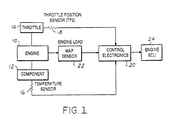
- an internal combustion engine 10 of an automobile comprises a major component 12 which may, for example, be a plastic intake manifold, and it also has a throttle 14 that is a part of a throttle mechanism that is controlled by the vehicle operator.
- a temperature sensor such as a thermistor 16 is associated with component 12 for measuring the component's temperature.
- a throttle position sensor (TPS) 18 is associated with the throttle mechanism for indicating the degree of opening of the throttle.
- the TPS 18 and thermistor 16 provide input signals to an over temperature control electronics designated by the numeral 20.
- the load on engine 10 is measured by a MAP sensor 22 which also supplies an input to over temperature control electronics 20.
- the output from over temperature control electronics 20 is in turn supplied to the engine electronic control unit (ECU) 24.
- ECU engine electronic control unit
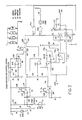
- FIG. 2 is detailed electronic schematic diagram of the over temperature control electronics 20.
- Temperature sensor thermistor 16 is connected in a series circuit with a resistor 26 across the five volt power supply that serves the control electronics.
- the junction of thermistor 16 and resistor 26 connects to the inverting input of a comparator circuit 28 and to the non-inverting input of another comparator circuit 30 that is configured to function as an amplifier.
- the amplified signal from circuit 30 is supplied to the non-inverting input of a comparator 32.
- comparator 32 The inverting input of comparator 32 is connected to a voltage divider circuit 34 that enables a selectable fraction of the five volt power supply voltage to be applied to the inverting input of comparator 32. With this arrangement, the output from comparator 32 will command load limiting when the temperature sensed by thermistor 16 rises above a selected set point, for example, 260°F.
- the non-inverting input of comparator 28 is connected to a voltage divider circuit 36 that can be set to provide a selectable reference to the non-inverting input of comparator 28.
- a voltage divider circuit 36 that can be set to provide a selectable reference to the non-inverting input of comparator 28.
- the throttle position sensor is connected to the inverting input of comparator 38 while the non-inverting input of the comparator is connected to a selectable reference value 40 corresponding to near closed or idle throttle position.
- the output from comparator 38 provides a signal of this indication to the input of a logic gate 42.
- the other input of logic gate 42 receives the output of comparator 28.
- Logic gate 42 functions to provide an output signal that will command load limiting only if the throttle position is in the near closed or idle position and the temperature sensed by thermistor 16 is above the lower set point.
- logic gate 42 and the output of comparator circuit 32 are inputs to another logic gate 44.
- Logic gate 44 will produce an output signal commanding load limiting if either the thermistor temperature is above the high set point or gate 42 is commanding limiting.
- the output of gate 44 controls the conductivity of two analog switches 46,48. The two switches are operated in a mutually exclusive manner such that when one switch is on, the other is off, and vice versa.
- the control input of switch 46 connects directly to the output of gate 44 while the control input of switch 48 connects to the output of gate 44 via an inverter circuit 50.
- Switches 46 and 48 control the delivery of the MAP sensor output to the engine ECU.
- the MAP sensor is connected to the engine ECU through a branch circuit 52 that contains switch 48, so that when switch 48 is conducting, the full value of the MAP sensor signal is delivered to the engine ECU.
- a second branch circuit 54 also connects the MAP sensor to the engine ECU.
- Branch 54 contains a voltage limiter circuit 56 and a voltage follower 58.
- the voltage limiter circuit 56 is responsive to the magnitude of the MAP sensor voltage and functions in the following manner. For MAP voltages that are less than a selected reference value of engine load, as set by limiter 56, the full value of the MAP signal can be transmitted through follower 58. However, for values of MAP signal exceeding the reference setting of limiter 56, the value of the MAP signal that can be passed through follower 58 is limited to the set value.
- the full value of the MAP signal is passed to the engine ECU whenever the sensed temperature is below the first set point.
- the full value of the MAP sensor signal is transmitted to the engine ECU so long as the throttle position sensor does not indicate a closed or near idle condition.
- the full value of the MAP sensor signal is passed to the engine ECU only for values of MAP sensor signal that are below the limit set by limiter 56 and if the MAP signal is above this limit then the value of MAP signal that is supplied to the engine ECU is at a limited value.
- the load signal delivered to the engine ECU is limited and therefore the engine will generate heat at a slower rate than it otherwise would and this extends the operating time of the engine beyond that which would otherwise occur in the overheated condition.
- over temperature control electronics can be embodied in a microprocessor type control directly rather than having a separate discrete circuit between the MAP sensor and the engine ECU.
Landscapes
- Engineering & Computer Science (AREA)
- Chemical & Material Sciences (AREA)
- Combustion & Propulsion (AREA)
- Mechanical Engineering (AREA)
- General Engineering & Computer Science (AREA)
- Theoretical Computer Science (AREA)
- Signal Processing (AREA)
- Electrical Control Of Air Or Fuel Supplied To Internal-Combustion Engine (AREA)
- Combined Controls Of Internal Combustion Engines (AREA)
Applications Claiming Priority (2)
| Application Number | Priority Date | Filing Date | Title |
|---|---|---|---|
| US07/367,273 US4945878A (en) | 1989-06-16 | 1989-06-16 | Extended over temperature operation and controls for ic engine |
| US367273 | 2003-02-14 |
Publications (2)
| Publication Number | Publication Date |
|---|---|
| EP0408876A1 true EP0408876A1 (de) | 1991-01-23 |
| EP0408876B1 EP0408876B1 (de) | 1993-12-01 |
Family
ID=23446530
Family Applications (1)
| Application Number | Title | Priority Date | Filing Date |
|---|---|---|---|
| EP90110395A Expired - Lifetime EP0408876B1 (de) | 1989-06-16 | 1990-05-31 | Steuerung und Erweiterung des Wirkungbereiches eines überhitzten Innenverbrennungsmotors |
Country Status (5)
| Country | Link |
|---|---|
| US (1) | US4945878A (de) |
| EP (1) | EP0408876B1 (de) |
| JP (1) | JPH0331561A (de) |
| CA (1) | CA2013885A1 (de) |
| DE (1) | DE69004880T2 (de) |
Families Citing this family (3)
| Publication number | Priority date | Publication date | Assignee | Title |
|---|---|---|---|---|
| US5555871A (en) * | 1995-05-08 | 1996-09-17 | Ford Motor Company | Method and apparatus for protecting an engine from overheating |
| US20020163198A1 (en) * | 2001-05-03 | 2002-11-07 | Gee Thomas Scott | Fail-safe engine cooling control algorithm for hybrid electric vehicle |
| US6682458B2 (en) * | 2002-06-19 | 2004-01-27 | Ford Motor Company | Method for operating a vehicle and a vehicle which incorporates the method |
Citations (3)
| Publication number | Priority date | Publication date | Assignee | Title |
|---|---|---|---|---|
| US4512307A (en) * | 1981-07-18 | 1985-04-23 | Nippon Soken, Inc. | Fuel quantity control apparatus of supercharged diesel engine with safety measures |
| EP0149902A2 (de) * | 1984-01-16 | 1985-07-31 | General Motors Corporation | Methode und Gerät um Kraftstoffzufuhr zu einem Motor zu steuern im Falle einer Kühlungsstörung |
| FR2612990A1 (fr) * | 1987-03-25 | 1988-09-30 | Motoren Werke Mannheim Ag | Dispositif de securite pour un moteur a combustion interne d e type diesel suralimente |
Family Cites Families (8)
| Publication number | Priority date | Publication date | Assignee | Title |
|---|---|---|---|---|
| JPS59107032U (ja) * | 1983-01-10 | 1984-07-19 | 日産自動車株式会社 | デイ−ゼルエンジンの燃料制御装置 |
| US4656973A (en) * | 1984-08-17 | 1987-04-14 | Instrument Sales And Service, Inc. | Temperature responsive engine control apparatus |
| US4641618A (en) * | 1985-11-08 | 1987-02-10 | Outboard Marine Corporation | Overspeed/overheat circuit with a latch for capacitive ignition systems |
| US4662316A (en) * | 1986-01-29 | 1987-05-05 | Nissan Motor Co., Ltd. | Cooling system for automotive engine or the like |
| JPS63100243A (ja) * | 1986-10-16 | 1988-05-02 | Fuji Heavy Ind Ltd | 燃料噴射装置 |
| DE3638131A1 (de) * | 1986-11-08 | 1988-05-11 | Audi Ag | Kuehlsystem einer wassergekuehlten fahrzeug-brennkraftmaschine |
| JPS6379475U (de) * | 1986-11-12 | 1988-05-25 | ||
| US4785784A (en) * | 1986-11-18 | 1988-11-22 | Nissan Motor Co., Ltd. | Fuel injection control system for internal combustion engine |
-
1989
- 1989-06-16 US US07/367,273 patent/US4945878A/en not_active Expired - Fee Related
-
1990
- 1990-04-04 CA CA002013885A patent/CA2013885A1/en not_active Abandoned
- 1990-05-31 EP EP90110395A patent/EP0408876B1/de not_active Expired - Lifetime
- 1990-05-31 DE DE90110395T patent/DE69004880T2/de not_active Expired - Fee Related
- 1990-06-15 JP JP2155593A patent/JPH0331561A/ja active Pending
Patent Citations (3)
| Publication number | Priority date | Publication date | Assignee | Title |
|---|---|---|---|---|
| US4512307A (en) * | 1981-07-18 | 1985-04-23 | Nippon Soken, Inc. | Fuel quantity control apparatus of supercharged diesel engine with safety measures |
| EP0149902A2 (de) * | 1984-01-16 | 1985-07-31 | General Motors Corporation | Methode und Gerät um Kraftstoffzufuhr zu einem Motor zu steuern im Falle einer Kühlungsstörung |
| FR2612990A1 (fr) * | 1987-03-25 | 1988-09-30 | Motoren Werke Mannheim Ag | Dispositif de securite pour un moteur a combustion interne d e type diesel suralimente |
Non-Patent Citations (1)
| Title |
|---|
| PATENT ABSTRACTS OF JAPAN, vol. 9, no. 297 (M-432)[2020], 25th November 1985; & JP-A-60 135 622 (SUZUKI JIDOSHA KOGYO K.K.) 19-07-1985 * |
Also Published As
| Publication number | Publication date |
|---|---|
| DE69004880T2 (de) | 1994-04-07 |
| EP0408876B1 (de) | 1993-12-01 |
| US4945878A (en) | 1990-08-07 |
| CA2013885A1 (en) | 1990-12-16 |
| JPH0331561A (ja) | 1991-02-12 |
| DE69004880D1 (de) | 1994-01-13 |
Similar Documents
| Publication | Publication Date | Title |
|---|---|---|
| US5239865A (en) | Process for monitoring the coolant level in a cooling system | |
| US4280457A (en) | System for monitoring and improving motor vehicle operating efficiency | |
| US5339782A (en) | Arrangement for controlling the drive power of a motor vehicle | |
| US6076500A (en) | Method and arrangement for controlling the torque of the drive unit of a motor vehicle | |
| US6732572B1 (en) | Method and device for monitoring and/or determining motor oil quality | |
| US5003785A (en) | Air-conditioning system for a vehicle | |
| US6032618A (en) | Cooling system for a motor-vehicle engine | |
| US5136880A (en) | Arrangement for detecting a changing operating parameter | |
| KR100817643B1 (ko) | 내연 기관 제어 방법 및 장치 | |
| US20010018632A1 (en) | Controller and storage medium for detecting cold engine operation | |
| KR0137362B1 (ko) | 공기조절 시스템의 압축기 제어 방법 | |
| US5090387A (en) | Method and arrangement for checking the operational capability of an exhaust-gas probe heater and the supply system thereof | |
| US5513614A (en) | Method for filling the fuel supply system in an internal combustion engine | |
| EP0761940B1 (de) | Verfahren zur Detektion einer Fehlfunktion in einer Kühlerlüfteranlage | |
| US5623902A (en) | Method and arrangement for idle adjustment of an internal combustion engine | |
| US4513712A (en) | Apparatus for regulating the idling rpm in an internal combustion engine | |
| US6368248B1 (en) | Method and device for controlling a drive unit of a vehicle | |
| JPH06221191A (ja) | 車両の可変量を検出する方法および装置 | |
| US5143553A (en) | Control apparatus of ignition current conducting time | |
| US4945878A (en) | Extended over temperature operation and controls for ic engine | |
| US5605128A (en) | Method and arrangement for idle adjustment of an internal combustion engine | |
| US4793308A (en) | Emergency control device for a diesel internal combustion engine with electronically controlled fuel proportioning | |
| US6234399B1 (en) | Method and means for determining malfunctioning of a thermostatic valve | |
| US4467762A (en) | Control apparatus for a fuel metering system | |
| US5224451A (en) | System for controlling an internal combustion engine |
Legal Events
| Date | Code | Title | Description |
|---|---|---|---|
| PUAI | Public reference made under article 153(3) epc to a published international application that has entered the european phase |
Free format text: ORIGINAL CODE: 0009012 |
|
| 17P | Request for examination filed |
Effective date: 19901108 |
|
| AK | Designated contracting states |
Kind code of ref document: A1 Designated state(s): DE FR GB |
|
| 17Q | First examination report despatched |
Effective date: 19910417 |
|
| GRAA | (expected) grant |
Free format text: ORIGINAL CODE: 0009210 |
|
| AK | Designated contracting states |
Kind code of ref document: B1 Designated state(s): DE FR GB |
|
| REF | Corresponds to: |
Ref document number: 69004880 Country of ref document: DE Date of ref document: 19940113 |
|
| ET | Fr: translation filed | ||
| PG25 | Lapsed in a contracting state [announced via postgrant information from national office to epo] |
Ref country code: GB Effective date: 19940531 |
|
| PLBE | No opposition filed within time limit |
Free format text: ORIGINAL CODE: 0009261 |
|
| STAA | Information on the status of an ep patent application or granted ep patent |
Free format text: STATUS: NO OPPOSITION FILED WITHIN TIME LIMIT |
|
| 26N | No opposition filed | ||
| GBPC | Gb: european patent ceased through non-payment of renewal fee |
Effective date: 19940531 |
|
| PG25 | Lapsed in a contracting state [announced via postgrant information from national office to epo] |
Ref country code: FR Effective date: 19950131 |
|
| PG25 | Lapsed in a contracting state [announced via postgrant information from national office to epo] |
Ref country code: DE Effective date: 19950201 |
|
| REG | Reference to a national code |
Ref country code: FR Ref legal event code: ST |