EP0408458B1 - Geschwindigkeitsregelvorrichtung für zwei- oder dreiphasige Motore - Google Patents
Geschwindigkeitsregelvorrichtung für zwei- oder dreiphasige Motore Download PDFInfo
- Publication number
- EP0408458B1 EP0408458B1 EP90402014A EP90402014A EP0408458B1 EP 0408458 B1 EP0408458 B1 EP 0408458B1 EP 90402014 A EP90402014 A EP 90402014A EP 90402014 A EP90402014 A EP 90402014A EP 0408458 B1 EP0408458 B1 EP 0408458B1
- Authority
- EP
- European Patent Office
- Prior art keywords
- phase
- motor
- memory
- switches
- control circuit
- Prior art date
- Legal status (The legal status is an assumption and is not a legal conclusion. Google has not performed a legal analysis and makes no representation as to the accuracy of the status listed.)
- Expired - Lifetime
Links
- 238000004804 winding Methods 0.000 claims description 42
- 230000015654 memory Effects 0.000 claims description 20
- 230000010363 phase shift Effects 0.000 claims description 9
- 125000004122 cyclic group Chemical group 0.000 claims description 5
- 238000005070 sampling Methods 0.000 claims description 5
- 230000003595 spectral effect Effects 0.000 claims 4
- 230000033764 rhythmic process Effects 0.000 claims 2
- 238000010586 diagram Methods 0.000 description 21
- 239000003990 capacitor Substances 0.000 description 11
- 239000004020 conductor Substances 0.000 description 5
- 230000008030 elimination Effects 0.000 description 5
- 238000003379 elimination reaction Methods 0.000 description 5
- 230000006870 function Effects 0.000 description 5
- 238000000354 decomposition reaction Methods 0.000 description 4
- 229920000297 Rayon Polymers 0.000 description 3
- 238000010894 electron beam technology Methods 0.000 description 3
- 238000012423 maintenance Methods 0.000 description 3
- 230000000737 periodic effect Effects 0.000 description 3
- 239000002964 rayon Substances 0.000 description 3
- 230000008901 benefit Effects 0.000 description 2
- 230000008859 change Effects 0.000 description 1
- 230000000295 complement effect Effects 0.000 description 1
- 239000002826 coolant Substances 0.000 description 1
- 230000000694 effects Effects 0.000 description 1
- 238000001914 filtration Methods 0.000 description 1
- 230000004907 flux Effects 0.000 description 1
- 230000006872 improvement Effects 0.000 description 1
- 230000001939 inductive effect Effects 0.000 description 1
- 150000002505 iron Chemical class 0.000 description 1
- 238000002955 isolation Methods 0.000 description 1
- 238000000034 method Methods 0.000 description 1
- 238000005457 optimization Methods 0.000 description 1
- 230000003071 parasitic effect Effects 0.000 description 1
- 230000009467 reduction Effects 0.000 description 1
- 230000004044 response Effects 0.000 description 1
Images


Classifications
-
- H—ELECTRICITY
- H05—ELECTRIC TECHNIQUES NOT OTHERWISE PROVIDED FOR
- H05G—X-RAY TECHNIQUE
- H05G1/00—X-ray apparatus involving X-ray tubes; Circuits therefor
- H05G1/08—Electrical details
- H05G1/66—Circuit arrangements for X-ray tubes with target movable relatively to the anode
Definitions
- the present invention relates to two-phase reciprocating motors and, more particularly, to a device for controlling the speed of such motors.
- such a tube is generally constituted as a diode, that is to say with a cathode 11 and an anode 12 or anti-cathode, these two electrodes 11 and 12 being enclosed in a vacuum-tight envelope 13 which makes it possible to achieve electrical isolation between these two electrodes.
- the cathode 11 produces an electron beam and the anode 12 receives these electrons over a small surface which constitutes a focal point from which the X-rays are emitted.
- anodic current When the high supply voltage is applied across the cathode 11 and anode 12, so that the cathode is at negative potential, a current called anodic current is established in the circuit, through a generator 14 producing the high supply voltage; the anode current crosses the space between the cathode and the anode in the form of the electron beam which bombards the hearth.
- a small proportion (1%) of the energy expended in producing the electron beam is transformed into X-rays.
- builders have long produced X-ray tubes with rotating anodes where the anode is rotated to distribute the heat flux over a ring called focal ring, with an area larger than the focal point, the advantage being all the greater as the speed rotation is generally high between 3,000 and 12,000 revolutions per minute.
- the rotary anode 12 of conventional type has the general shape of a disc having an axis of symmetry 17 around which it is rotated by means of an electric motor.
- the electric motor has a stator 15 located outside the casing 13 and a rotor 16 mounted in the casing and arranged along the axis of symmetry 17, the rotor being mechanically secured to the anode via d 'a support shaft 18.
- This motor is generally of the asynchronous type so that it does not require the creation of an inducing field by the rotor.
- the energy dissipated in such a tube is high and it is therefore planned to cool it.
- the tube is enclosed in an enclosure or sheath 19 in which a coolant 19, in particular oil, is circulated.
- Rotation of the anode at high speeds leads to rapid wear of the motor bearings. Also, to extend their service life as well as to reduce the Joule losses of the engine which are dissipated in the sheath containing the X-ray tube, the anode is not driven at high speed continuously, which means that it at least two rotational speeds are provided, one high for the actual radiological exposure and the other lower between two exposures, the latter possibly being zero.
- the diagrams in FIG. 2 show, by way of example, two operating cycles of the rotating anode of an X-ray tube, one 20 for a 0.3 mm focal point and the other 21 for a 0.1 mm focus.
- the two cycles are identical and include a first phase A which corresponds to starting the engine, a second phase B of speed maintenance (3,000 rpm or 9,000 rpm) and a third phase C of braking until engine shutdown.
- the motors which are used to produce rotating anodes are generally of the two-phase type and the electrical diagram which makes it possible to carry out an operating cycle is for example that of FIG. 3.
- the motor 30 is represented under the form of a so-called main phase winding 31 and a so-called auxiliary phase winding 32 in series with a phase shift capacitor 33.
- This capacitor 33 performs, for the frequency considered, the quadrature supply of the two windings 31 and 32
- These two windings 31 and 32 are supplied by a single-phase alternating voltage 34 via a transformer 35 and relay contacts 36 and 37 in series on supply conductors 38 and 39.
- the common point of the windings 31 and 32 is connected directly to the secondary winding of the transformer 35.
- the two conductors 38 and 39 are connected by a conductor 29 disposed between the contacts of the relays 36 and 37.
- the latter rotates at a speed of 3,000 revolutions / minute when the supply frequency is 50 Hertz.
- a rotation speed of 9,000 revolutions / minute it is sufficient to triple the frequency of the single-phase sector using a device using, for example, a saturated iron transformer and by changing the phase shift capacitor 33 to the using a switch (not shown).
- One of the solutions that is adopted is to use a single-phase inverter which supplies a two-phase motor whose auxiliary phase is in series with a phase-shifting capacitor.
- This solution has the disadvantage of requiring switching, in particular to adapt the phase shift capacitors to the speed and to obtain braking.
- there is no optimization of the inverter-motor assembly because, in particular, the capacitor, on the one hand, achieves the desired phase shift with low precision as a function of its own tolerance and that of the motor and, on the other hand, it causes an increase in the current harmonics in the auxiliary phase.
- FIG. 4 The electrical diagram in principle is that of FIG. 4.
- the winding 31 of the main phase is supplied by a first inverter 44 represented by four switches 45, 46, 47 and 48 while the winding 32 of the auxiliary phase is supplied by a second inverter 49 represented by four switches 50, 51, 52 and 53.
- each switch can be considered to be composed of a transistor or a thyristor associated with an antiparallel diode.
- a capacitor 54 constitutes the input filter of inverters 44 and 49 which are supplied with direct current by a source 43.
- a third solution consists in using a motor 66 whose stator allows a three-phase winding, this winding being supplied by a three-phase inverter according to the diagram in FIG. 5.
- the inverter 55 comprises three pairs or pairs of switches 56 and 57, 58 and 59, 60 and 61, each common point A, B or C of which is connected to a winding 62 for switches 56 and 57, to a winding 63 for switches 58 and 59 and to a winding 64 for switches 60 and 61.
- the filtering capacitor is referenced 65.
- switches 56 to 60 are controlled by a device 67 which provides control signals for said switches.
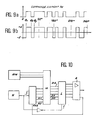
- the control signals are such that the waveforms VA, VB, VC, measured between the common points A, B and C of the switches and the negative pole of the power supply, are given by the diagrams figures 6-a, 6-b and 6-c. These are square signals 120 ° out of phase with each other.
- the diagrams of figures 6-d, 6-e and 6-f give the result of the combination of these waveforms between them such that the figure 6-d corresponds to VA-VB, the figure 6-e to VB- VC and the figure 6-f corresponds to VC-VA.
- These waveforms commonly called pseudosinusoidal waves, are 120 ° out of phase with each other.
- the easier realization of the three-phase winding of the motor allows an improvement in the performance of the motor, which allows a shorter ramp-up time (phase A).
- the operation of such a device leads to a natural elimination, in the motor, of harmonics of current of multiple rank of three which, like the intermediate harmonics, do not provide useful torque but on the contrary create parasitic currents and cause losses.
- we obtain a reduction in the input filter because the frequency of the ripple imposed by the three-phase motor is tripled, which reduces the value of the capacity of the filter capacitor 65.
- stator has a number of notches which is a multiple of three so as to allow a three-phase winding.
- the invention relates to a device for controlling a two-phase motor, characterized by the features of claim 1 or claim 2.
- FIG. 7 is the block diagram of a device for controlling the speed of a two-phase motor 85 as described for example in document US-A-4,829,551, said motor comprising a winding 82 of main phase and a auxiliary phase winding 83.
- This device comprises a three-phase inverter 70 which is supplied with direct current by a source 71 and which is controlled by a circuit 86.
- a capacitor 72 serves as a filter element.
- the inverter 70 comprises three pairs or pairs of switches 73 and 74, 75 and 76, 77 and 78, each common point D, E and F of which is connected respectively to the winding 82 of the main phase, at the common point 84 of the two windings 82 and 83 and the auxiliary phase winding 83.
- switches 73 to 78 are controlled by a circuit 86 which supplies control signals for said switches.
- These switches 73 to 78 are preferably produced by conventional electronic components such as transistors or thyristors, associated with diodes in reverse parallel.
- the control pulses of switches 73 to 78 must be such that the voltage applied to winding 83 of the auxiliary phase is 90 ° out of phase with that applied to winding 82 of the main phase.
- these voltages must not contain harmonics of low rank which do not contribute to increasing the motor torque knowing that the harmonics of high rank are not annoying because the corresponding currents are low due to the high value of the self- inductances of windings 82 and 83 for these high frequencies.
- FIGS. 8-d and 8-e show as a function of time, the waveforms VD, VE and VF in voltages which are obtained respectively at the common points D, E and F of the couples of switches (73.74), (75.76) and (77.78). These are square pulses which are 90 ° out of phase with each other.
- the voltage which is applied to the main phase winding 82 results from the difference (VD-VE) (figure 8-d) while the voltage which is applied to the auxiliary phase winding 83 results from the difference (VE- VF) (figure 8-e).
- VD-VE the difference
- VE- VF auxiliary phase winding
- the last column on the right gives the harmonic contents in the case of the waveforms (VA-VB), (VB-VC) and (VC-VA) of figures 6-d, 6-e, and 6-f, feeding a three-phase motor.
- the harmonic currents which are superimposed on the useful fundamental current are penalizing vis-à-vis the inverter but especially vis-à-vis the motor because they reduce the useful flow and cause the motor to heat up. It is therefore important to eliminate them.
- harmonics of high rank for example greater than 13, the corresponding voltages are filtered by the inductances of the windings which have high values at these frequencies so that the corresponding currents are low and have an effect. negligible harm.
- the figure 9-a represents the sequence of command of the switch 74 of the figure 7, complementary to that of the switch 73, then the figure 9-b represents the tension taken at the point D compared to a fictitious point of potential E half of that of the direct supply voltage of value 2E.
- This criterion can be, for example, the cancellation of the first two harmonics, either b3 and b5 for a two-phase motor, and b5 and b7 for a three-phase motor.
- the criterion can be different, for example, tolerating a specified harmonic percentage for each row up to a certain row. It is clear that if one wishes to cancel three coefficients b n , it will be necessary to choose a sampling waveform having switching instants at the angles ⁇ ′1, ⁇ ′2, ⁇ ′3 and ⁇ ′4 and calculate these angles using a system of four equations as defined above.
- the calculation of the angles ⁇ 1, ⁇ 2 and ⁇ 3 using the system of equations defined above is carried out by a computer, for example by successive approximations.
- the values of ⁇ 1, ⁇ 2, ⁇ 3 ... therefore define the waveform which must be obtained at point D, for example in FIG. 7.
- the waveforms at points E and F are deduced from that in D by an offset of 90 °.
- the states of the switches of the inverter over a period with the switching at the angles ⁇ 1, ⁇ 2, ⁇ 3 thus determined and the necessary phase shifts are recorded in a memory of the control circuit 86 of FIG. 7 and the cyclic reading of this memory makes it possible to control switches 73 to 78.
- the speed variation can be obtained either continuously by varying the frequency of the read signal, or in a discrete manner by calculating the programming over a number of steps corresponding to a fixed frequency of the read signal and to the desired speed.
- the invention which has just been described therefore enables a two-phase motor to be rotated at variable speed using a three-phase inverter 70 with elimination of the most troublesome harmonics by calculating the values ⁇ 1, ⁇ 2, ⁇ 3 ...
- the even inverter 70 can run a three-phase motor with elimination of unwanted harmonics.
- the switch control device is preferably of the type described in FIG. 10.
- a counter C periodically reset to zero by a command applied to its reset reset input sends address signals, A0 , A1 ... to a memory M. This sending is carried out at the rate given by a clock H. The values of the addresses are incremented with the counter.
- the memory delivers, in response to these addresses, instructions DO, D1 to a buffer circuit L.
- the buffer circuit L is also controlled by the clock H (via an inverter).
- the buffer circuit L is connected, at its output, to a circuit A of control amplifiers for the switches (triggering of the triggers of the thyristors).
- a coding circuit RM relating to the engine speed makes it possible to select an adequate programming of the memory M. to obtain the desired voltage and speed and for the two-phase or three-phase type of motor.
- the operation of the circuit of FIG. 10 is as follows.
- the instructions issued by the memory are identical to each other for all the durations of the periods. These instructions therefore change value at times ⁇ 1, ⁇ 2, ⁇ 3 ...
- memory M has six outputs D0 to D5 (to control the six switches) which can according to the instruction, take a state 0 (corresponding to the opening of a switch) or a state 1 (closing of a switch). In this way, it is possible to control, at the rate of the clock, the switches corresponding to a phase for a chosen speed.
- the available memories have eight outputs. In this way, there is an additional output, the 7th or the 8th, to control the reset of the counter. This simply occurs when the counter delivers an address corresponding to the end of a cycle.
- the control circuit of FIG. 10 is also used for this purpose.
- the memory RM one of the pages M is selected from the memory M, so that the amplifier circuit A controls the inverter as a chopper.
- the control circuit of FIG. 10 can therefore judiciously fulfill this role.
Landscapes
- Control Of Ac Motors In General (AREA)
- Inverter Devices (AREA)
Claims (8)
- Steuervorrichtung für einen Zweiphasenelektromotor (85) mit einer Hauptphasenwicklung (82) und einer Hilfsphasenwicklung (83), die an einem gemeinsamen Punkt (84) verbunden und mit zwei Enden versehen sind, die folgendes aufweist: eine Wechselrichterschaltung (70) des Dreiphasentyps, die aus drei Schalterpaaren (73-78) gebildet ist, deren gemeinsame Punkte (D, E, F) mit den beiden Enden bzw. dem gemeinsamen Punkt der beiden Wicklungen des Motors verbunden sind und drei um 90° zueinander phasenverschobene Kurvenformen aufweisen; sowie eine Steuerschaltung (86) für das Öffnen und Schließen der Schalter, wobei die Steuerschaltung Abtastmittel für die Grundfrequenz der drei Kurvenformen aufweist, so daß die Umschaltzeitpunkte (ϑ1-ϑn) in jeder Periode bezüglich der 90°-Phase symmetrisch und bezüglich der 180°-Phase invers sind, um die Spektralanteile mit geradem Rang zu eliminieren, und in einer Viertelperiode mit Hilfe einer Fourierreihenzerlegung berechnet sind, um bestimmte Spektralanteile mit ungeradem Rang und für eine Anzahl m von Grundfrequenzen ganz oder teilweise zu eliminieren, einen Speicher (M) zum Speichern der berechneten Werte der Umschaltzeitpunkte in getrennten Teilen sowie Mittel zum zyklischen Lesen des Speichers für die Berechnung der Umschaltzeitpunkte, und wobei die Drehzahländerung kontinuierlich durch Änderung der Frequenz des Lesesignals erhalten wird.
- Steuervorrichtung für einen Zweiphasenelektromotor (85) mit einer Hauptphasenwicklung (82) und einer Hilfsphasenwicklung (83), die an einem gemeinsamen Punkt (84) verbunden und mit zwei Enden versehen sind, die folgendes aufweist: eine Wechselrichterschaltung (70) des Dreiphasentyps, die aus drei Schalterpaaren (73-78) gebildet ist, deren gemeinsame Punkte (D, E, F) mit den beiden Enden bzw. dem gemeinsamen Punkt der beiden Wicklungen des Motors verbunden sind und drei um 90° zueinander phasenverschobene Kurvenformen aufweisen; sowie eine Steuerschaltung (86) für das Öffnen und Schließen der Schalter, wobei die Steuerschaltung Abtastmittel für die Grundfrequenz der drei Kurvenformen aufweist, so daß die Umschaltzeitpunkte (ϑ1-ϑn) in jeder Periode bezüglich der 90°-Phase symmetrisch und bezüglich der 180°-Phase invers sind, um die Spektralanteile mit geradem Rang zu eliminieren, und in einer Viertelperiode mit Hilfe einer Fourierreihenzerlegung berechnet sind, um bestimmte Spektralanteile mit ungeradem Rang und für eine Anzahl m von Grundfrequenzen ganz oder teilweise zu eliminieren, einen Speicher (M) zum Speichern der berechneten Werte der Umschaltzeitpunkte in getrennten Teilen sowie Mittel zum zyklischen Lesen des Speichers für die Berechnung der Umschaltzeitpunkte, und wobei die Drehzahländerung diskret erhalten wird, indem die Programmierung in einer Anzahl von Schritten berechnet wird, die einer festen Frequenz des Lesesignals und der gewünschten Drehzahl entspricht.
- Vorrichtung nach Anspruch 1 oder 2, dadurch gekennzeichnet, daß die Steuerschaltung ferner eine Codierschaltung (RM) bezüglich des Betriebsbereichs des Motors aufweist, die die Auswahl einer geeigneten Programmierung des Speichers aufweist, um die für den Motor gewünschte Spannung und Drehzahl zu erhalten.
- Vorrichtung nach Anspruch 3, dadurch gekennzeichnet, daß die Zustände der Schalter der Wechselrichterschaltung über eine Periode mit den Umschaltzeitpunkten und den erforderlichen Phasenverschiebungen in dem Speicher aufgezeichnet sind, und daß die Steuerung der Schalter durch das zyklische Lesen dieses Speichers realisiert werden kann.
- Vorrichtung nach einem der Ansprüche 1 bis 4, dadurch gekennzeichnet, daß die Steuerschaltung zum Anlegen eines Gleichstroms an die Hauptwicklung des Motors zum Bremsen des Motors verwendet wird.
- Vorrichtung nach Anspruch 5, dadurch gekennzeichnet, daß die Steuerschaltung einen Pseudogleichstrom liefert, der stets in der gleichen Richtung orientiert ist, um diesen Gleichstrom an die Hauptwicklung des Motors anzulegen.
- Vorrichtung nach Anspruch 6, dadurch gekennzeichnet, daß die Steuerschaltung eine Verstärkerschaltung (A) aufweist und die Codierschaltung (M) in dem Speicher eine seiner Seiten so auswählt, daß die Verstärkerschaltung die Wechselrichterschaltung wie einen Zerhacker steuert.
- Vorrichtung nach Anspruch 7, dadurch gekennzeichnet, daß die Steuerschaltung einen periodisch auf Null zurückgestellten Zähler (C) aufweist, der in dem von einem Taktgeber gegebenen Rhythmus Adressensignale (A0, A1, ...) zu dem Speicher schickt, wobei die Werte der Adressen mit dem Zähler inkrementiert werden und der Speicher in Reaktion auf diese Adressen im Rhythmus des Taktgebers Anweisungen (Do, D1, ...) an die Verstärkerschaltung liefert.
Applications Claiming Priority (2)
| Application Number | Priority Date | Filing Date | Title |
|---|---|---|---|
| FR8909546 | 1989-07-13 | ||
| FR8909546A FR2649840B1 (fr) | 1989-07-13 | 1989-07-13 | Dispositif de commande de la vitesse de moteurs diphases ou triphases |
Publications (2)
| Publication Number | Publication Date |
|---|---|
| EP0408458A1 EP0408458A1 (de) | 1991-01-16 |
| EP0408458B1 true EP0408458B1 (de) | 1994-11-30 |
Family
ID=9383813
Family Applications (1)
| Application Number | Title | Priority Date | Filing Date |
|---|---|---|---|
| EP90402014A Expired - Lifetime EP0408458B1 (de) | 1989-07-13 | 1990-07-12 | Geschwindigkeitsregelvorrichtung für zwei- oder dreiphasige Motore |
Country Status (4)
| Country | Link |
|---|---|
| US (1) | US5105141A (de) |
| EP (1) | EP0408458B1 (de) |
| DE (1) | DE69014453T2 (de) |
| FR (1) | FR2649840B1 (de) |
Families Citing this family (20)
| Publication number | Priority date | Publication date | Assignee | Title |
|---|---|---|---|---|
| DE4232134A1 (de) * | 1992-09-25 | 1994-03-31 | Philips Patentverwaltung | Schaltungsanordnung zum Speisen eines Zweiphasen-Asynchronmotors |
| US6232742B1 (en) * | 1994-08-02 | 2001-05-15 | Aerovironment Inc. | Dc/ac inverter apparatus for three-phase and single-phase motors |
| FI97654C (fi) * | 1994-09-09 | 1997-01-27 | Abb Industry Oy | Menetelmä epätahtikoneen käynnistämiseksi |
| DE4438037A1 (de) * | 1994-10-25 | 1996-05-02 | Philips Patentverwaltung | Antriebsvorrichtung für eine Drehanode |
| GB2310322A (en) * | 1996-02-13 | 1997-08-20 | Dana Corp | Winding structure for operating a two phase motor from a three phase source |
| RU2144729C1 (ru) * | 1998-07-29 | 2000-01-20 | Новосибирский государственный технический университет | Векторный способ управления преобразователем |
| US6864648B1 (en) * | 2002-02-08 | 2005-03-08 | Powersci, Inc | Vector flux machine |
| RU2231203C2 (ru) * | 2002-07-30 | 2004-06-20 | Государственное образовательное учреждение высшего профессионального образования Московский энергетический институт (технический университет) | Трехфазный непосредственный преобразователь частоты для асинхронного электропривода |
| DE10357503A1 (de) * | 2003-12-09 | 2005-07-07 | BSH Bosch und Siemens Hausgeräte GmbH | Ansteuerung eines Gleichstrommotors |
| DE112006001258T5 (de) * | 2005-05-17 | 2008-04-30 | Denso Corp., Kariya | Motor und Steuereinheit dafür |
| US7911107B2 (en) * | 2005-05-24 | 2011-03-22 | Denso Corporation | AC electric motor |
| US7808201B2 (en) * | 2005-06-09 | 2010-10-05 | International Rectifier Corporation | Sensorless field oriented controller for two-phase motor |
| US20070278984A1 (en) * | 2006-05-31 | 2007-12-06 | Rodwan Tarek Adra | 2-Phase switched reluctance device and associated control topologies |
| CN101815471A (zh) * | 2007-09-04 | 2010-08-25 | 断层放疗公司 | 患者支承装置及操作方法 |
| JP5797960B2 (ja) * | 2010-08-24 | 2015-10-21 | アスモ株式会社 | ブラシレスモータの駆動方法及びブラシレスモータの駆動回路、並びに、ブラシレスモータの回転位置の検出方法及びブラシレスモータの回転位置の検出回路 |
| US9443633B2 (en) | 2013-02-26 | 2016-09-13 | Accuray Incorporated | Electromagnetically actuated multi-leaf collimator |
| JP7166789B2 (ja) * | 2017-05-23 | 2022-11-08 | キヤノンメディカルシステムズ株式会社 | X線診断システム及び陽極回転コイル駆動装置 |
| RU2677682C1 (ru) * | 2017-11-29 | 2019-01-21 | Федеральное государственное автономное образовательное учреждение высшего образования "Национальный исследовательский Томский политехнический университет" | Вентильный электропривод колебательного движения |
| US11051388B2 (en) * | 2018-06-30 | 2021-06-29 | Varex Imaging Corporation | X-ray tube diagnostic system including a circuit to generate a phase signal and/or an indication of a status of a motor |
| EP3663871B1 (de) * | 2018-12-06 | 2026-02-18 | The Swatch Group Research and Development Ltd | Motorantrieb eines dc-elektromotors |
Family Cites Families (5)
| Publication number | Priority date | Publication date | Assignee | Title |
|---|---|---|---|---|
| US4006391A (en) * | 1974-12-20 | 1977-02-01 | E-Systems, Inc. | Linearized pulse width modulator |
| JPS60131096A (ja) * | 1983-12-20 | 1985-07-12 | Mitsubishi Electric Corp | 2相90度電動機 |
| CA1292769C (en) * | 1986-11-12 | 1991-12-03 | Errol E. Wallingford | Three-phase pwm inverter with speed control and load compensation for aninduction motor |
| JPH07110153B2 (ja) * | 1987-08-31 | 1995-11-22 | 株式会社安川電機 | 二相誘導電動機の駆動制御用インバータ制御装置 |
| US4829551A (en) * | 1988-01-13 | 1989-05-09 | Picker International, Inc. | Biphase quadrature drive for an x-ray tube rotor |
-
1989
- 1989-07-13 FR FR8909546A patent/FR2649840B1/fr not_active Expired - Fee Related
-
1990
- 1990-07-12 EP EP90402014A patent/EP0408458B1/de not_active Expired - Lifetime
- 1990-07-12 DE DE69014453T patent/DE69014453T2/de not_active Expired - Fee Related
- 1990-07-12 US US07/551,888 patent/US5105141A/en not_active Expired - Lifetime
Non-Patent Citations (1)
| Title |
|---|
| IEEE TRANS. ON INDUSTRY APPLICATIONS VOL IA-9, NO 3, MAY/JUNE 1973 ; H.S. PATEL ET AL : "GENERALIZED TECHNIQUES OF HARMONIC ELIMINATION AND VOLTAGE CONTROL IN THYRYSTOR INVERTERS - PART 1 HARMONIC ELIMINATION" * |
Also Published As
| Publication number | Publication date |
|---|---|
| US5105141A (en) | 1992-04-14 |
| FR2649840A1 (fr) | 1991-01-18 |
| FR2649840B1 (fr) | 1991-12-20 |
| DE69014453T2 (de) | 1995-05-18 |
| EP0408458A1 (de) | 1991-01-16 |
| DE69014453D1 (de) | 1995-01-12 |
Similar Documents
| Publication | Publication Date | Title |
|---|---|---|
| EP0408458B1 (de) | Geschwindigkeitsregelvorrichtung für zwei- oder dreiphasige Motore | |
| FR2652960A1 (fr) | Circuit d'alimentation electrique pour un transducteur piezo-electrique. | |
| EP1320920B1 (de) | Schaltnetzteil | |
| FR2550029A1 (fr) | Systeme de commande pour des moteurs synchrones sans balais utilisant une commande d'angle de couple | |
| FR2768273A1 (fr) | Dispositif de conversion de l'energie a butee auto-adaptive et son procede de fonctionnement | |
| EP0783201A1 (de) | Elektromotor des Synchrontyps mit Permanentmagneten und mit einem solchen Motor ausgestattetes Fahrzeug | |
| FR2717966A1 (fr) | Circuit de commande pour un moteur à commutation de phases. | |
| EP0727866B1 (de) | Vorrichtung zur Steuerung eines Elektromotors mit veränderlicher Drehzahl | |
| FR2503959A1 (fr) | Circuit destine a fournir un courant en dents de scie | |
| FR2768241A1 (fr) | Dispositif et procede de regulation a commande optimale d'un convertisseur a transistors | |
| EP0486359B1 (de) | NF-Schaltsteuerschaltung für Feldeffekttransistoren und Bipolartransistoren mit isoliertem Gate | |
| EP0670624B1 (de) | Angepasstes Schaltnetzteil um Kommutierungen bei niedriger Spannung auszuführen | |
| FR2667723A1 (fr) | Dispositif d'obtention et de commutation de hautes tensions de polarisation d'electrodes de tube a rayons x. | |
| EP1444768B1 (de) | Verfahren und einrichtung zur transformation einer gleichspannung und verwendung der einrichtung | |
| EP2715927B1 (de) | Verfahren zur steuerung der schalter eines stromrichtergerätes verbunden mit eingebautem ladegerät | |
| FR2735919A1 (fr) | Dispositif d'alimentation d'un moteur a reluctance variable | |
| EP2302768B1 (de) | Vorrichtung zur Gleichstromversorgung einer Rotorspulenanordnung einer synchron umlaufenden elektrischen Maschine, und Antriebssystem, das mit solch einer Einspeisvorrichtung ausgestattet ist | |
| FR2493066A1 (fr) | Procede et dispositif pour produire un courant alternatif a partir d'une source electrique a courant continu | |
| CH618295A5 (en) | Electric machine with variable number of poles | |
| FR3143237A1 (fr) | Procédé de commande d’une machine électrique pilotée par un onduleur pourvu d’une pluralité de bras de commutation | |
| FR2711861A1 (fr) | Générateur de tension continue à commande optimale. | |
| CA1065401A (fr) | Soutirage en serie d'energie d'une ligne de transport htcc | |
| CH156586A (fr) | Installation électrique pour corriger les oscillations de la tension aux bornes d'un circuit à courant continu alimenté par l'intermédiaire d'un redresseur de courant alternatif. | |
| BE486623A (de) | ||
| WO2021229190A1 (fr) | Autotransformateur, unité autotransformateur-redresseur et procédé de connexion d'un équipement électrique à un réseau triphasé au moyen d'une unité autotransformateur-redresseur |
Legal Events
| Date | Code | Title | Description |
|---|---|---|---|
| PUAI | Public reference made under article 153(3) epc to a published international application that has entered the european phase |
Free format text: ORIGINAL CODE: 0009012 |
|
| AK | Designated contracting states |
Kind code of ref document: A1 Designated state(s): DE ES GB NL |
|
| 17P | Request for examination filed |
Effective date: 19910130 |
|
| 17Q | First examination report despatched |
Effective date: 19921209 |
|
| GRAA | (expected) grant |
Free format text: ORIGINAL CODE: 0009210 |
|
| AK | Designated contracting states |
Kind code of ref document: B1 Designated state(s): DE ES GB NL |
|
| PG25 | Lapsed in a contracting state [announced via postgrant information from national office to epo] |
Ref country code: NL Effective date: 19941130 Ref country code: GB Effective date: 19941130 Ref country code: ES Free format text: THE PATENT HAS BEEN ANNULLED BY A DECISION OF A NATIONAL AUTHORITY Effective date: 19941130 |
|
| REF | Corresponds to: |
Ref document number: 69014453 Country of ref document: DE Date of ref document: 19950112 |
|
| NLV1 | Nl: lapsed or annulled due to failure to fulfill the requirements of art. 29p and 29m of the patents act | ||
| GBV | Gb: ep patent (uk) treated as always having been void in accordance with gb section 77(7)/1977 [no translation filed] |
Effective date: 19941130 |
|
| PLBE | No opposition filed within time limit |
Free format text: ORIGINAL CODE: 0009261 |
|
| STAA | Information on the status of an ep patent application or granted ep patent |
Free format text: STATUS: NO OPPOSITION FILED WITHIN TIME LIMIT |
|
| 26N | No opposition filed | ||
| PGFP | Annual fee paid to national office [announced via postgrant information from national office to epo] |
Ref country code: DE Payment date: 20070831 Year of fee payment: 18 |
|
| PG25 | Lapsed in a contracting state [announced via postgrant information from national office to epo] |
Ref country code: DE Free format text: LAPSE BECAUSE OF NON-PAYMENT OF DUE FEES Effective date: 20090203 |