EP0407662B2 - Gerät zum Positionieren einer Boje - Google Patents
Gerät zum Positionieren einer Boje Download PDFInfo
- Publication number
- EP0407662B2 EP0407662B2 EP89201874A EP89201874A EP0407662B2 EP 0407662 B2 EP0407662 B2 EP 0407662B2 EP 89201874 A EP89201874 A EP 89201874A EP 89201874 A EP89201874 A EP 89201874A EP 0407662 B2 EP0407662 B2 EP 0407662B2
- Authority
- EP
- European Patent Office
- Prior art keywords
- buoy body
- tubular member
- ballast weight
- buoy
- elongate tubular
- Prior art date
- Legal status (The legal status is an assumption and is not a legal conclusion. Google has not performed a legal analysis and makes no representation as to the accuracy of the status listed.)
- Expired - Lifetime
Links
Images

Classifications
-
- B—PERFORMING OPERATIONS; TRANSPORTING
- B63—SHIPS OR OTHER WATERBORNE VESSELS; RELATED EQUIPMENT
- B63B—SHIPS OR OTHER WATERBORNE VESSELS; EQUIPMENT FOR SHIPPING
- B63B22/00—Buoys
- B63B22/02—Buoys specially adapted for mooring a vessel
- B63B22/021—Buoys specially adapted for mooring a vessel and for transferring fluids, e.g. liquids
- B63B22/025—Buoys specially adapted for mooring a vessel and for transferring fluids, e.g. liquids and comprising a restoring force in the mooring connection provided by means of weight, float or spring devices
Definitions
- the invention relates to a device according to the preamble of claim 1.
- Such a device is known from GB-A-2,015,455 of applicant, wherein a buoy body is described having a substantial flat shape.
- the invention aims to obviate these drawbacks. According to the invention this is realized by the features of the characterising part of claim 1.
- ballast weight and anchor line Because of the cooperative action of the buoy body, ballast weight and anchor line a considerable displacement of an anchored vessel can be realized before the connection from the vessel to the sea bottom is in a straight line. Through the use of several anchor lines connected to the ballast weight a considerable momentum against tilting of the ballast weight is provided by the weight of the anchor lines. Because of this the resistance against movement of the buoy body will increase during its displacement not only because of increased buoyancy at submerging of the buoy body, but also because of the tilting action of the ballast weight.
- the coupling means comprise at least one articulated connection to one of said buoy body, and said ballast weight.
- Such a structure will preferably be used in deep water where the forces acting on the several components will be increased considerably. Even if the articulation joint is between the connecting means and the ballast weight the tilting momentum described above of the ballast weight is realized because of the tensile force tending to place the ballast weight under an angle relative to the sea bottom.
- this disadvantage is obviated in that said tubular member is embodied such that a substantial rigid connection between the buoy body and the ballast weight is obtained.
- the device according to the invention acts as a tumbler such that when a vessel exerts a traction force to the buoy body it will not longer remain in the same horizontal position with regard to the water surface as with the prior art but tilted.
- Flow lines from the ballast weight can be routed through the tubular member, such that a much better protection is obtained against exterior influences than with the device according to the prior art in which the flow lines were outside of the link member.
- a swivel body is provided at the buoy body.
- This swivel preferably comprises at least two spaced bearings rotatably mounted relative to said tubular member. Because of this an increased distance between the bearings is possible resulting in an structural improved embodiment.
- the buoy body is provided with an end cap at its end remote from the ballast weight and at least one opening for the flow line(s) in the swivel is located below water level.
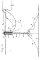
- the device according to the invention is generally indicated with 1 and comprises a ballast weight 2, a riser 3 and buoy body 4.
- the device 1 is designed to anchor a vessel 5 of which only a part is shown.
- Flow lines 7,8,9 connect the sea bed 6 with the vessel 5.
- Ballast weight 2 is connected with anchor and anchor lines 10 to sea bed 6.
- Vessel 5 is connected to buoy body 4 with mooring line 11.
- Between riser 3 and buoy body 4 bearings 13,14 are provided such that buoy body 4 acts like a swivel relative to riser 3.
- the end of flow line 8 is connected to conduit 15 by means (not shown) to enable a rotation of buoy body 4 relative to riser 3.
- the conduit 15 opens near 16 e.g. below water level from buoy body.
- riser 3 is fixed to ballast weight 2 and rotatably connected to buoy body 4. This means that if a traction force is exerted on mooring line 11 both buoy body 4 and ballast weight 2 will tilt giving a larger restoring moment compared with devices described in the prior art. Because of the fixed connection between riser 3 and ballast weight 2 it is relatively simple to introduce flow line 7 in riser 3 (flow line 8) where it is protected against exterior influences. By having flow line 9 below sea level as much as possible also this flow line is protected against the influences of waves, ice etc. After vessel 5 has been disconnected from buoy body anchor line 11 and flow line 9 will be in the position indicated with chain lines respectively 19 and 17 because of the presence of floating body 18. Also in this condition these lines are protected against influences acting near sea level.
- ballast weight 2 is provided with an articulating joint 20 to a riser 21.
- Buoy body 22 is provided with swivel 23 having an articulating joint 24 being connected to riser 21.
- the flow line is indicated with 25, 26, 27, 28. Because of the articulation joints 20, 24 it is not preferable to have the flow line inside riser 21, 29 indicates the bearing of the swivel 23 buoy body 22.
- the embodiment according to Fig. 2 is particular useful if large bending moments are to be expected. An articulated connection can avoid larger bending moments than the rigid connection shown in Fig. 1.
Landscapes
- Chemical & Material Sciences (AREA)
- Engineering & Computer Science (AREA)
- Combustion & Propulsion (AREA)
- Mechanical Engineering (AREA)
- Ocean & Marine Engineering (AREA)
- Laying Of Electric Cables Or Lines Outside (AREA)
- Bridges Or Land Bridges (AREA)
Claims (6)
- Vertäuvorrichtung mit einem in der Gebrauchslage oberen Bojenkörper (4, 22), der ein Drehgelenk mit zwei gegeneinander verdrehbaren Teilen aufweist, von denen eines einen Festmacher-Anschluß für ein Schiff aufweist, während das andere Teil mit einem länglichen Rohrteil (3, 21) verbunden ist, das sich nach unten erstreckt und an seinem unteren Ende ein Ballastgewicht (2) trägt, das zu seiner Festlegung am Meeresboden mit sich in unterschiedlichen Richtungen erstreckenden Ankerseilen versehen ist, wobei sich zur Verbindung mit einem Schiff bzw. mit dem Meeresgrund Flüssigkeitsleitungen von dem oberen Bojenkörper über das genannte Rohrteil bis zum unteren Ballastgewicht erstrecken, dadurch gekennzeichnet, daß die mittlere horizontale Querschnittabmessung des Bojenkörpers kleiner ist als seine Höhe, so daß die im Einsatz befindliche Vertäuvorrichtung bei Beaufschlagung mit Wellen zumindest bei hoher See untertaucht und/oder sich unter Einwirkung einer von einem vertäuten Schiff ausgeübten Zugkraft signifikant aus ihrer Vertikalstellung in eine Schrägstellung neigt, wobei die Verbindung des oberen Bojenkörpers mit dem Ballastgewicht über das längliche Rohrteil so ausgebildet ist, daß bei der Auslenkung der Vertäuvorrichtung aus ihrer vertikalstellung ein Rückstellmoment über das Rohrteil wirksam wird.
- Vorrichtung nach Anspruch 1, dadurch gekennzeichnet, daß das längliche Rohrteil (3, 21) zumindest eine Gelenkverbindung (20, 24) aufweist.
- Vorrichtung nach Anspruch 1, gekennzeichnet durch eine derartige Ausbildung des länglichen Rohrteils (3, 21), daß sich eine im wesentlichen starre Verbindung zwischen Bojenkörper (4, 22) und Ballastgewicht (2) ergibt.
- Vorrichtung nach einem der vorhergehenden Ansprüche, dadurch gekennzeichnet, daß das Drehgelenk zumindest zwei voneinander beabstandete Lager (29) aufweist, die gegenüber dem länglichen Rohrteil (3) drehbar angeordnet sind.
- Vorrichtung nach einem der vorhergehenden Ansprüche, dadurch gekennzeichnet, daß der Bojenkörper (4) an seinem dem Ballastgewicht (2) gegenüberliegenden Ende mit einer Stirnkappe und unterhalb des Wasserspiegels mit zumindest einer Öffnung für die Leitungen (15) versehen ist.
- Vorrichtung nach einem der vorhergehenden Ansprüche, dadurch gekennzeichnet, daß der Bojenkörper (4, 22) Schaummaterial enthält.
Priority Applications (2)
| Application Number | Priority Date | Filing Date | Title |
|---|---|---|---|
| EP89201874A EP0407662B2 (de) | 1989-07-14 | 1989-07-14 | Gerät zum Positionieren einer Boje |
| US07/622,164 US5098323A (en) | 1989-07-14 | 1990-12-03 | Device for positioning of a buoy body |
Applications Claiming Priority (1)
| Application Number | Priority Date | Filing Date | Title |
|---|---|---|---|
| EP89201874A EP0407662B2 (de) | 1989-07-14 | 1989-07-14 | Gerät zum Positionieren einer Boje |
Publications (3)
| Publication Number | Publication Date |
|---|---|
| EP0407662A1 EP0407662A1 (de) | 1991-01-16 |
| EP0407662B1 EP0407662B1 (de) | 1993-06-16 |
| EP0407662B2 true EP0407662B2 (de) | 1999-06-23 |
Family
ID=8202435
Family Applications (1)
| Application Number | Title | Priority Date | Filing Date |
|---|---|---|---|
| EP89201874A Expired - Lifetime EP0407662B2 (de) | 1989-07-14 | 1989-07-14 | Gerät zum Positionieren einer Boje |
Country Status (2)
| Country | Link |
|---|---|
| US (1) | US5098323A (de) |
| EP (1) | EP0407662B2 (de) |
Families Citing this family (10)
| Publication number | Priority date | Publication date | Assignee | Title |
|---|---|---|---|---|
| US5162005A (en) * | 1991-01-16 | 1992-11-10 | Single Buoy Moorings, Inc. | Mooring device |
| US5305703A (en) * | 1992-12-31 | 1994-04-26 | Jens Korsgaard | Vessel mooring system |
| GB2296904B (en) * | 1995-03-03 | 1996-12-18 | Victoria Oilfield Dev | Mooring and Flowline System |
| US5944448A (en) * | 1996-12-18 | 1999-08-31 | Brovig Offshore Asa | Oil field installation with mooring and flowline system |
| US5951061A (en) * | 1997-08-13 | 1999-09-14 | Continental Emsco Company | Elastomeric subsea flex joint and swivel for offshore risers |
| US6210075B1 (en) * | 1998-02-12 | 2001-04-03 | Imodco, Inc. | Spar system |
| NO312358B1 (no) * | 2000-07-20 | 2002-04-29 | Navion Asa | Offshore laste- eller produksjonssystem for et dynamisk posisjonert skip |
| NO316504B1 (no) * | 2002-06-17 | 2004-02-02 | Advanced Production And Loading As | Forankringssystem |
| NO20082053L (no) * | 2008-04-29 | 2009-10-30 | Statoilhydro Asa | Anordning av fleksible stigeror |
| NO347179B1 (en) * | 2020-07-14 | 2023-06-19 | Semar As | A mooring system for a plurality of floating units |
Family Cites Families (13)
| Publication number | Priority date | Publication date | Assignee | Title |
|---|---|---|---|---|
| US3077614A (en) * | 1960-07-20 | 1963-02-19 | Robert L Lloyd | Buoy for mooring vessels |
| US3103020A (en) * | 1960-09-13 | 1963-09-10 | California Research Corp | Mooring buoy assembly |
| US3390408A (en) * | 1966-05-09 | 1968-07-02 | Global Marine Inc | Long spar buoy structure and erection method |
| US3604030A (en) * | 1969-06-30 | 1971-09-14 | Harold E Claflin | Buoy for mooring vessels |
| US3782458A (en) * | 1971-08-04 | 1974-01-01 | Gray Tool Co | Upright, swivelable buoyed conduit for offshore system |
| NL7312778A (en) * | 1973-09-17 | 1975-03-19 | Ihc Holland Nv | Mooring buoy for loading or discharging vessel - uses reinforced flexible transfer hose as mooring connection |
| NL167910C (nl) * | 1974-11-05 | 1982-02-16 | Single Buoy Moorings | Afmeerinrichting. |
| NL168459C (nl) * | 1975-05-23 | 1982-04-16 | Single Buoy Moorings | Eenpunts meerboeisamenstel. |
| GB2015455B (en) * | 1978-03-07 | 1983-02-02 | Single Buoy Moorings | Device for positioning a body having buoyancy |
| US4326312A (en) * | 1979-04-30 | 1982-04-27 | Amtel, Inc. | Single leg mooring terminal |
| US4310937A (en) * | 1979-08-30 | 1982-01-19 | Amtel, Inc. | Mooring terminal with top mounted fluid swivel |
| NL8202738A (nl) * | 1982-07-07 | 1984-02-01 | Single Buoy Moorings | Drijvende inrichting. |
| NL8302203A (nl) * | 1983-06-21 | 1985-01-16 | Single Buoy Moorings | Afmeerboei. |
-
1989
- 1989-07-14 EP EP89201874A patent/EP0407662B2/de not_active Expired - Lifetime
-
1990
- 1990-12-03 US US07/622,164 patent/US5098323A/en not_active Expired - Lifetime
Also Published As
| Publication number | Publication date |
|---|---|
| EP0407662A1 (de) | 1991-01-16 |
| US5098323A (en) | 1992-03-24 |
| EP0407662B1 (de) | 1993-06-16 |
Similar Documents
| Publication | Publication Date | Title |
|---|---|---|
| AU624056B2 (en) | Offshore loading system | |
| RU2196701C2 (ru) | Система для загрузки судов в море | |
| US5505560A (en) | Fluid transfer system for an offshore moored floating unit | |
| EP0096446B1 (de) | System zum Halten eines Schwimmkörpers in einer festen Position relativ zu einem anderen Körper | |
| US4031582A (en) | Floating structure | |
| EP0096445B2 (de) | System zum Halten eines Schwimmkörpers in einer festen Position relativ zu einem anderen Körper | |
| US5816183A (en) | Submerged CALM buoy | |
| EP0407662B2 (de) | Gerät zum Positionieren einer Boje | |
| RU97108291A (ru) | Погружной буй с якорным креплением на опорах в виде цепи | |
| EP1080007B1 (de) | Umschlagrohrsystem | |
| JP3704153B2 (ja) | 浅い水域において使用するための積み込みおよび積み降ろし用ブイアレンジメント | |
| US4262620A (en) | Mooring device | |
| EP0079404B2 (de) | Einpunkt-Verankerungsboje mit starrem Arm | |
| US4309955A (en) | Riser-to-vessel-mooring-terminal | |
| EP0096119B1 (de) | Einpunktbefestigungs-System mit starrem Arm für schwimmende Fahrzeuge | |
| GB2043008A (en) | Permanent single-point mooring system | |
| US4254522A (en) | Single-point mooring buoy | |
| US4254523A (en) | Mooring installation | |
| US4798155A (en) | Mooring device | |
| EP0049549A1 (de) | Vertäuboje | |
| EP0134596A1 (de) | Verankerungsboje | |
| US4802432A (en) | Mooring device | |
| GB2292360A (en) | Mooring buoy | |
| US4654015A (en) | Mooring installation | |
| CN1164211A (zh) | 浸没式悬索锚臂系船浮筒 |
Legal Events
| Date | Code | Title | Description |
|---|---|---|---|
| PUAI | Public reference made under article 153(3) epc to a published international application that has entered the european phase |
Free format text: ORIGINAL CODE: 0009012 |
|
| AK | Designated contracting states |
Kind code of ref document: A1 Designated state(s): AT BE CH DE ES FR GB GR IT LI LU NL SE |
|
| RBV | Designated contracting states (corrected) |
Designated state(s): FR GB IT NL |
|
| REG | Reference to a national code |
Ref country code: DE Ref legal event code: 8566 |
|
| 17P | Request for examination filed |
Effective date: 19910712 |
|
| 17Q | First examination report despatched |
Effective date: 19920807 |
|
| ITF | It: translation for a ep patent filed |
Owner name: DE DOMINICIS & MAYER S.R.L. |
|
| GRAA | (expected) grant |
Free format text: ORIGINAL CODE: 0009210 |
|
| AK | Designated contracting states |
Kind code of ref document: B1 Designated state(s): FR GB IT NL |
|
| ET | Fr: translation filed | ||
| PLBI | Opposition filed |
Free format text: ORIGINAL CODE: 0009260 |
|
| 26 | Opposition filed |
Opponent name: BLUEWATER TERMINAL SYSTEMS NV Effective date: 19940314 |
|
| NLR1 | Nl: opposition has been filed with the epo |
Opponent name: BLUEWATER TERMINAL SYSTEMS NV. |
|
| PLAW | Interlocutory decision in opposition |
Free format text: ORIGINAL CODE: EPIDOS IDOP |
|
| PLAW | Interlocutory decision in opposition |
Free format text: ORIGINAL CODE: EPIDOS IDOP |
|
| PUAH | Patent maintained in amended form |
Free format text: ORIGINAL CODE: 0009272 |
|
| STAA | Information on the status of an ep patent application or granted ep patent |
Free format text: STATUS: PATENT MAINTAINED AS AMENDED |
|
| 27A | Patent maintained in amended form |
Effective date: 19990623 |
|
| AK | Designated contracting states |
Kind code of ref document: B2 Designated state(s): FR GB IT NL |
|
| ET3 | Fr: translation filed ** decision concerning opposition | ||
| NLR2 | Nl: decision of opposition | ||
| ITF | It: translation for a ep patent filed |
Owner name: DE DOMINICIS & MAYER S.R.L. |
|
| NLR3 | Nl: receipt of modified translations in the netherlands language after an opposition procedure | ||
| REG | Reference to a national code |
Ref country code: GB Ref legal event code: IF02 |
|
| PGFP | Annual fee paid to national office [announced via postgrant information from national office to epo] |
Ref country code: NL Payment date: 20040528 Year of fee payment: 16 |
|
| PGFP | Annual fee paid to national office [announced via postgrant information from national office to epo] |
Ref country code: GB Payment date: 20040621 Year of fee payment: 16 |
|
| PGFP | Annual fee paid to national office [announced via postgrant information from national office to epo] |
Ref country code: FR Payment date: 20040721 Year of fee payment: 16 |
|
| PG25 | Lapsed in a contracting state [announced via postgrant information from national office to epo] |
Ref country code: IT Free format text: LAPSE BECAUSE OF NON-PAYMENT OF DUE FEES;WARNING: LAPSES OF ITALIAN PATENTS WITH EFFECTIVE DATE BEFORE 2007 MAY HAVE OCCURRED AT ANY TIME BEFORE 2007. THE CORRECT EFFECTIVE DATE MAY BE DIFFERENT FROM THE ONE RECORDED. Effective date: 20050714 Ref country code: GB Free format text: LAPSE BECAUSE OF NON-PAYMENT OF DUE FEES Effective date: 20050714 |
|
| PG25 | Lapsed in a contracting state [announced via postgrant information from national office to epo] |
Ref country code: NL Free format text: LAPSE BECAUSE OF NON-PAYMENT OF DUE FEES Effective date: 20060201 |
|
| GBPC | Gb: european patent ceased through non-payment of renewal fee |
Effective date: 20050714 |
|
| PG25 | Lapsed in a contracting state [announced via postgrant information from national office to epo] |
Ref country code: FR Free format text: LAPSE BECAUSE OF NON-PAYMENT OF DUE FEES Effective date: 20060331 |
|
| NLV4 | Nl: lapsed or anulled due to non-payment of the annual fee |
Effective date: 20060201 |
|
| REG | Reference to a national code |
Ref country code: FR Ref legal event code: ST Effective date: 20060331 |