EP0407625B1 - Méthode et appareil pour déterminer le centre d'une ligne dans un élément microminiaturisé - Google Patents
Méthode et appareil pour déterminer le centre d'une ligne dans un élément microminiaturisé Download PDFInfo
- Publication number
- EP0407625B1 EP0407625B1 EP89112541A EP89112541A EP0407625B1 EP 0407625 B1 EP0407625 B1 EP 0407625B1 EP 89112541 A EP89112541 A EP 89112541A EP 89112541 A EP89112541 A EP 89112541A EP 0407625 B1 EP0407625 B1 EP 0407625B1
- Authority
- EP
- European Patent Office
- Prior art keywords
- light
- measurement signal
- line
- signal
- reference signal
- Prior art date
- Legal status (The legal status is an assumption and is not a legal conclusion. Google has not performed a legal analysis and makes no representation as to the accuracy of the status listed.)
- Expired - Lifetime
Links
- 238000000034 method Methods 0.000 title claims description 49
- 238000005259 measurement Methods 0.000 claims description 74
- 230000003287 optical effect Effects 0.000 claims description 29
- 238000012545 processing Methods 0.000 claims description 25
- 230000004304 visual acuity Effects 0.000 claims description 14
- 239000011521 glass Substances 0.000 claims description 9
- 230000002596 correlated effect Effects 0.000 claims description 8
- 230000004397 blinking Effects 0.000 claims description 5
- 238000001914 filtration Methods 0.000 claims description 5
- 238000005286 illumination Methods 0.000 claims description 5
- 230000001360 synchronised effect Effects 0.000 claims description 5
- 238000012634 optical imaging Methods 0.000 claims description 4
- 238000006073 displacement reaction Methods 0.000 claims description 3
- 238000012937 correction Methods 0.000 description 9
- 238000011156 evaluation Methods 0.000 description 8
- 238000010586 diagram Methods 0.000 description 6
- 230000000875 corresponding effect Effects 0.000 description 5
- 238000001514 detection method Methods 0.000 description 5
- 238000004519 manufacturing process Methods 0.000 description 4
- 230000008901 benefit Effects 0.000 description 3
- 230000008030 elimination Effects 0.000 description 3
- 238000003379 elimination reaction Methods 0.000 description 3
- 230000009467 reduction Effects 0.000 description 3
- 238000000691 measurement method Methods 0.000 description 2
- 239000004065 semiconductor Substances 0.000 description 2
- 230000003247 decreasing effect Effects 0.000 description 1
- 230000001419 dependent effect Effects 0.000 description 1
- 230000000694 effects Effects 0.000 description 1
- 238000005530 etching Methods 0.000 description 1
- 230000006870 function Effects 0.000 description 1
- 238000001459 lithography Methods 0.000 description 1
- 230000010355 oscillation Effects 0.000 description 1
- 229920002120 photoresistant polymer Polymers 0.000 description 1
- 238000005293 physical law Methods 0.000 description 1
- 230000010287 polarization Effects 0.000 description 1
- 230000008569 process Effects 0.000 description 1
- 238000013064 process characterization Methods 0.000 description 1
- 238000002310 reflectometry Methods 0.000 description 1
- 230000002123 temporal effect Effects 0.000 description 1
- 230000001960 triggered effect Effects 0.000 description 1
Images
Classifications
-
- G—PHYSICS
- G01—MEASURING; TESTING
- G01B—MEASURING LENGTH, THICKNESS OR SIMILAR LINEAR DIMENSIONS; MEASURING ANGLES; MEASURING AREAS; MEASURING IRREGULARITIES OF SURFACES OR CONTOURS
- G01B11/00—Measuring arrangements characterised by the use of optical techniques
- G01B11/02—Measuring arrangements characterised by the use of optical techniques for measuring length, width or thickness
Definitions
- the present invention relates to a technique utilized in the fabrication of microminiature devices and, more particularly, to a method and an apparatus for determining line centers in a microminiature element such as on a semiconductor wafer or a mask having linewidths and other feature spacings below the one micron range.
- Linewidth measurement and the determination of line centers is well known in the integrated circuit fabrication industry for process characterization and tool evaluation.
- linewidth measurement is valuable in the evaluation of lithography systems or particular steps in a photoresist or etching process.
- EP-A-0013 325 describes an optical system that is particularly adapted for accurate, nondestructive measurement of surface features encountered in semi-conductor manufacturing.
- a spot of laser light is focussed on the surface of the object and then scanned across the features of interest.
- Light reflected from the edges and surface of the object is detected by photomultipliers which generate signals with peaks representing the edges. Linewidths or distances are then obtained by computing the location differences between the peaks appearing in the multiplier signals.
- PTB-Mitannonen Forschen + Pruefen, Vol. 95, 1/85, pp. 1-10 discloses the determining of edges on lines having a linewidth in the range of one micron.
- the edges are determined by two focussed laser scan spots on the object being illuminated successively with a distance below the classic resolving power.
- the signals generated by a photodetector which receives the light reflected from the edges and the surfaces of the object are processed. After several steps and a final differential step linewidths are obtained by computing locations of signal peaks. This method is directed on the determination of edges having a mutual distance of about one micron.
- the disclosed method and apparatus are not suitable for determining lines in the submicron range because of the shape and the small distance of the signal peaks which increase the measurement error to a high degree. Further, the error is negatively influenced by the analog signal processing and the differential step which causes additional high frequency errors.
- the present invention comprises well known techniques which are combined and modified such that the new method and the apparatus can determine lines with a linewidth down to 0.25 micron.
- the method and the apparatus determine the line center of the scanned line in order to obtain results with a minimum of errors.
- the method and apparatus of the present invention use a light beam illumination arrangement which generates a light beam which is directed on the object.
- the light reflected by the object is measured. This technique is well known as indicated above.
- step A) of the method two focussed laser spots are directed on the object, both being illuminated successively with a distance below the classic resolving power (0.61 x wavelength / numerical aperture).
- the distance of the spots is about 0.2 micron which is obtained by 0.4 x wavelength / numerical aperture as described in PTB-Mitanderen.
- the illumination can be accomplished by using two different laser spots whereof one is lightened to the same extent as the other one is darkened, or by using only one spot which oscillates between the two locations with a distance below the classic resolving power.
- the scanning of the lines as described in step B) along a line across the line to be determined can be accomplished by moving a conventional X-Y table relative to the laser spots or by scanning the line by moving the laser spots. Both techniques are state of the art.
- Steps C) and D) which refer to the processing of an analog electrical measurement signal are known as well from PTB-Mitteilungen.
- the signal reflected by the scanned line comprises a DC component which varies with the reflectivity of the object.
- This DC component is superposed with an AC component which is generated by the oscillation of the two laser spots.
- the AC component of the signal obtained comprises the information which can be used to determine the line center of the scanned line.
- the DC component has to be eliminated.
- the high frequency noise components produced by the laser and the scanning are eliminated in order to provide an appropriate measurement signal. This is accomplished by a tuned amplifier which allows a simple and fast elimination of the high frequency noise.
- step E the maximum and minimum values of the filtered measurement signal are digitized. That means that only the values of the peaks of the AC component are digitized for further digital processing. Thus a reduction of data is achieved which have to be processed by the determination of the scanned line. It is also possible to develop the digitized maximum and minimum values in two steps: first, digitization of the total signal, and subsequent by the reduction of data by erasing the digitized values except the maximum and minimum values, but the latter method needs more memory capacity and processing time.
- the sine shaped curves represent the envelope of the AC component signal and are both correlated to each other. They are formed by maximum/minimum and minimum/maximum values, respectively, lying on the respective curve of an envelope.
- step H The following evaluation of the digital values of the sine shaped curves is accomplished by step H) of the inventive method.
- step H the intersection point of the two sine shaped curves is computed.
- the method according to this invention it is possible to determine the center of lines in the submicron range with a small error only and in real time. This is promoted by a more accurate determination of the intersection point of two curves, both having a slope in comparison to an intersection point determination of only one curve and by computing the curves and the intersection point.
- step G The result can be improved by modifying step G) with an additional digital filtering of the measurement signal in order to eliminate further noise on this signal.
- an additional reference signal can be generated which is considered with the processing of the digital values of the measurement signal.
- This reference signal is preferably processed corresponding and in parallel to the measurement signal, and after the parallel digitization the line center is computed on the basis of the measurement signal and the reference signal.
- step A) is modified so that after generating two successively illuminated laser spots part of the light of at least one of said laser spots is outcoupled. The residue of the two laser spots is then directed and focussed on the object with a distance below the classic resolving power.
- the outcoupling of the light can be accomplished by several optical means.
- the method comprises steps for parallel processing of the outcoupled light to generate a useful reference signal.
- the steps applied to the outcoupled light correspond to steps applied to the light reflected by the object.
- an analog electrical reference signal is developed from the outcoupled light;
- a filtered reference signal is generated by eliminating the DC component and the high frequency noise components of the electrical reference signal of step c); and
- the maximum and minimum values of said filtered reference signal are digitized. Further, it is necessary to combine the digitized values of the measurement and the reference signal.
- step F This can be accomplished by an additional step F) inserted between steps E) and G) in which the digitized values obtained in steps E) and e) of the measurement signal and the reference signal, respectively, are synchronously processed to generate a correlated measurement signal with eliminated low frequency noise.
- Both signals have to be synchronized in order to correlate the digitized values of each signal with respect to time.
- step D) the filtering in step d) can be accomplished with a tuned amplifier.
- a further reduction of measurement errors can be obtained by a further embodiment of the invention in which a glass plate is inserted as a beam splitter in the optical path of the laser beams to outcouple the light for the reference signal.
- a glass plate is inserted as a beam splitter in the optical path of the laser beams to outcouple the light for the reference signal.
- errors generated by the use of a laser scanner can be eliminated.
- the relative movement between the object and the laser spots is accomplished by a scanning movement of the spots across the object.
- This feature of the inventive method can occur in combination with the reference signal or without reference signal and removes the errors which arise by the movement of the laser beam in the optical arrangement.
- these errors only depend on the location of the laser beam in the optical instruments during the scanning movement. These errors are constant for one optical arrangement if there are no changes in the arrangement and no differences in temperature between the error determination procedure and the measurement procedure.
- step F is modified in synchronized processing of the digitized values of the measurement signal, the reference signal and digitized values of a correction signal.
- the correction signal With the correction signal the above-mentioned local intensity variations are considered, and with this modified step the low frequency noise and the local intensity variations are eliminated.
- the signals are correlated to each other in respect of time and location in order to compute the digital values of the corresponding measurement points. The removal of the variations which depend on the time and the location is accomplished by computing for each measurement point a corrected measurement value dependent on the location of the scanning laser spots.
- the digitized values of the correction signal are usually obtained only once for the optical measurement arrangement and before the the first measurement procedure.
- the digitized correction signal values are obtained by directing one of said laser spots of said laser illumination arrangement on an optically homogeneous reflecting surface; moving said laser scanner spots along a line across said surface in which case the deflection correlates with the movement of the laser scanner on the object to be determined; developing an analog electrical correction signal of the light reflected from said surface; digitizing the minimum and maximum values of said correction signal; storing the digitized values with reference to the location of said laser scanner movement.
- the apparatus for implementing the method uses a measurement signal and a reference signal, both handled as described above.
- the apparatus comprises an optical imaging system including means for generating two laser scanner spots which are focussed on the object with a distance below the classic resolving power.
- An optical imaging system is disclosed in PTB-Mitteilungen which uses a laser, several optical polarization means, and for generating the two laser spots, among others an opto-electronical modulator and a Wollaston prism.
- Other systems like a mirror which oscillates with high frequency, for example, are applicable as well.
- the light of one laser beam then oscillates on the object with a predetermined distance while by using the opto-electronical modulator and the Wollaston prism one laser beam is divided into two laser beams with different vibration directions which are illuminated alternatively on the object with a predetermined distance.
- the reflected light is then guided to first receiving means by conventional optical means.
- the optical system includes means for outcoupling the light of said laser scanner spots and guiding the outcoupled light to second receiving means.
- the first and second receiving means include photo-detectors which provide an electrical measurement signal and reference signal, respectively.
- the apparatus further comprises means for effecting relative movement between the optical system and the object in a plane parallel to the surface of the object such that the spot scans along a line across the line to be determined.
- the apparatus comprises means for processing digital signals which synchronously controls said relative movement with said means for generating the laser scanner spots, receives from said first receiving means said measurement signal and from said second receiving means said reference signal, and detects the position of the line center.
- the apparatus comprises memory means which stores the position of the line center and supplies said movement means with this position.
- the first and second receiving means additionally comprise a tuned amplifier and an analog/digital converter which develop first a filtered analog signal without DC components and high frequency noise and then provide a digitized signal.
- a glass plate inserted in the optical path of the laser beams with an inclination corresponding to the Brewster angle serves as a beam splitter.
- the method is modified so that one blinking light spot is generated from which part of the light is outcoupled before the light spot is directed and focussed on the object.
- white light or laser light can be used for generating the blinking light spot.
- the spot is scanned along a line across a line as discussed above.
- the processing of the obtained measurement signal and the reference signal corresponds to the processing of the measurement signal and the reference signal of the method described before. Subsequently, the measurement signal and the reference signal are correspondingly digitized and synchronously processed. Additionally a correction signal can be considered and processed as discussed in connection with the scanning spot.
- one or two sine shaped curves of an envelope both being correlated to each other are generated.
- the first of said sine shaped curves is generated by computing the difference quotient of the curve which is created by the digitized maximum values and the second by computing the difference quotient of the curve which is created by the digitized minimum values.
- the generation of the difference quotient is accomplished by computing instead of by using two laser spots as in the method described hereinabove. The distance of the two laser spots below the classic resolving power is considered by a corresponding displacement during the computing of the difference quotient which follows common mathematical laws. After this computing one or two sine shaped curves are obtained.
- the detection of the line center is then accomplished by the determination of the intersection point of one of the sine shaped curves with the zero line or of the intersection point of the two sine shaped curves.
- the measurement signal Before this processing in order to detect the line center the measurement signal can be digitally filtered.
- the apparatus for implementing this single point method uses another assembly for generating one light spot.
- This assembly comprises an optical system which includes means for generating a blinking light spot.
- a further advantage of the present invention is the application of the method in the dark field as well as in the bright field.
- Another advantage of the invention described herein is the application in conventional optical systems and microscopes.
- the invention allows the determination of the line center and thus of distances in real time, so that manufacturing processes are not retarded by this measurement method and apparatus.
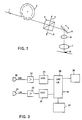
- a light beam 1 is chopped into pulses by a rotating chopper wheel 2 which additionally provides the trigger pulses for the evaluation of the light reflected by the object.
- the light beam 1 passes a beam splitter 3 which outcouples part of the light of the light beam 1 as a reference light beam 4.
- the residue of light beam 1 is directed via a scanning mirror 5, an ocular 6 and an objective 7 on the object 8.
- the scanning mirror 5, the ocular 6 and the objective 7 are parts of common microscopes, spectrometers or similar optical devices.
- the light reflected by the object reaches the beam splitter 3 via the objective 7 and the ocular 6, and the beam splitter 3 reflects a measurement light beam 9 to a photodetector 30 of Fig. 3.
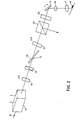
- a linearly polarized laser beam 16 is directed to an electrooptical light modulator 17 which is triggered by a digital signal processor 36 (Fig. 3).
- the electrooptical light modulator 17 generates in conjunction with the quarter-wave plate 18 and a +/- quarter-wave voltage at the electrooptical light modulator 17 two waves which are linearly polarized at right angles.
- the wavelength of the quarter-wave voltage is the wavelength of the laser light.
- the Wollaston prism 19 the waves are deflected in different directions depending on the polarizing direction with a splitting angle of about one minute. This results in two partially overlapping light spots in the object plane which are alternately lightened up. The distance of the spots is below the classic resolving power and is about 0.4 x wavelength / numerical aperture.
- the two laser light beams which result in the two laser spots in the object plane pass a glass plate 20 which serves as a beam splitter.
- a glass plate 20 which serves as a beam splitter.
- the glass plate 20 is inserted in the optical path under an angle of about 57 degrees (Brewster angle) only part of one polarizing direction (perpendicular to the plane of incidence) is reflected and thus outcoupled for later signal processing.
- the other polarizing direction (parallel with the plane of incidence) is not reflected and passes through the glass plate 20.
- the two laser light beams pass the half-wave plate 21 in order to turn the vibration direction of the light beams such that from each vibration direction an equal part passes the following polarizing beam splitter 22.
- the following quarter-wave plate 23 effects the rotation of the vibration direction such that after the reflection of the light from the object the light beam is reflected by the beam splitter 22 to the photodetector 30 of Fig. 3.
- the arrangement according to Fig. 2 utilizes as well a scanning mirror 5, an ocular 6 and an objective 7 to focus the light on the object 8. All these optical parts can be members of a microscope, spectrometer or similar optical devices.
- Fig. 3 is a block diagram showing a processing system for the line center detection and is designed to receive the output of the photodetector 30 of the measurement light beam 9 and the output of a photodetector 31 of the reference light beam 4.
- Both photodetectors 30, 31 generate an analog electrical signal and are connected with tuned amplifiers 32 and 33, respectively.
- the tuned amplifiers 32, 33 both having the same time constant, the high frequency noise and the DC component in each signal are eliminated.
- the filtered signals from the tuned amplifiers are digitized by analog/digital converters (ADC) 34, 35, respectively, which digitize only the maximum and minimum values of each signal and which are then processed in a digital signal processor (DSP) 36.
- ADC analog/digital converters
- the DSP is further connected with a position unit 37 which supplies the DSP 36 with the current relative position between the scanning beam and the object and with a light pulse trigger unit 38 which controls the generation of light pulses by the chopper wheel 2 or the light modulator 17.
- the DSP controls the synchronized processing by analog/digital converters 34 and 35, the position unit 37 and the light pulse trigger unit 38. Dates are stored in the memory 39.
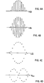
- Fig. 4a shows the analog electrical measurement signal at the output of the photodetector 30 when using the single point method. After filtering this signal by the tuned amplifier 32, the signal course according to Fig. 4b is obtained. The maximum values and the minimum values of the measurement signal of Fig. 4b and the equivalent evaluated reference signal are digitized and processed to eliminate the low frequency noise and to generate one measurement signal which forms envelopes according to Fig. 4c. Subsequently, the maximum values and/or the minimum values are used to compute the difference quotient with respect to the resolving power below the classic resolving power. Fig. 4d shows the difference quotient of the maximum values and the minimum values. The intersection point of the two difference quotient courses of the maximum and the minimum values indicates the line center. It is also possible to use the difference quotient of either the maximum or the minimum values to detect the line center as the intersection point with the zero line.
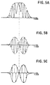
- Fig. 5 discloses the signal evaluation of the method using two laser spots which are focussed on the object.
- Fig. 5a shows the measurement generated by the photodetector 30.
- the signal according to Fig. 5b is obtained.
- the maximum and minimum values are digitized and the envelope as indicated with dashed lines in Fig. 5b is formed as shown in Fig. 5c.
- Fig. 5c discloses the processed measurement signal which is formed from the measurement signal and the reference signal of and from which the low frequency noise is eliminated (low frequency noise subtraction).
- the intersection point of the two envelopes is the line center of the line to be detected.
- the signals can be digitally filtered in order to eliminate remaining noise on the curves and to allow the accurate determination of the intersection point.
- Fig.4 and 5 only schematically show the signal courses, i.e. the high frequency noise and the low frequency noise are not depicted.
Landscapes
- Physics & Mathematics (AREA)
- General Physics & Mathematics (AREA)
- Length Measuring Devices By Optical Means (AREA)
- Testing Or Measuring Of Semiconductors Or The Like (AREA)
Claims (11)
- Méthode pour déterminer le centre d'une ligne dans un élément microminiaturisé en utilisant un agencement d'éclairage à faisceau laser et la mesure de la lumière réfléchie par les lignes de l'objet, ladite méthode comprenant les étapes suivantes:A) diriger deux spots laser focalisés sur ledit objet lesquels sont tous deux éclairés successivement avec une distance inférieure au pouvoir de résolution classique;B) balayer lesdites lignes en déplaçant lesdits spots laser le long d'une ligne transversalement à la ligne à déterminer;C) produire un signal de mesure électrique analogique de la lumière réfléchie par la ligne balayée;D) engendrer un signal de mesure filtré en éliminant la composante de courant continu et les composantes de bruit haute fréquence dudit signal de mesure électrique;E) numériser les valeurs maximale et minimale dudit signal de mesure électrique;G) traiter lesdites valeurs numérisées dudit signal de mesure afin d'engendrer deux courbes sinusoïdales d'une enveloppe lesquelles sont toutes deux en corrélation entre elles, et formées respectivement par les valeurs maximale/minimale et les valeurs minimale/maximale dudit signal de mesure se trouvant sur la courbe respective d'une enveloppe;H) déterminer numériquement le point d'intersection desdites deux courbes comme étant le centre de ligne de la ligne balayée.
- Méthode selon la revendication 1, dans laquelle l'étape G) comprend en outre
le filtrage numérique dudit signal de mesure avant le traitement desdites valeurs numérisées afin d'éliminer le bruit sur ledit signal. - Méthode selon les revendications 1 ou 2,
dans laquelle l'étape A) est étendue pour comprendre ce qui suit:A) engendrer deux spots laser qui sont éclairés successivement, rejeter une partie de la lumière d'au moins un des deux spots laser avant de les diriger et de les focaliser sur ledit objet avec une distance inférieure au pouvoir de résolution classique; et
dans laquelle la méthode comprend les étapes à insérer entre les étapes B) et C),c) produire un signal de référence électrique analogique provenant de ladite lumière rejetée;d) engendrer un signal de référence filtré en éliminant la composante de courant continu et les composantes de bruit haute fréquence dudit signal de référence électrique;e) numériser les valeurs maximale et minimale dudit signal de référence filtré;
et dans laquelle l'étape suivante F) est ensuite insérée entre les étapes E) et G):
traitement synchronisé desdites valeurs numérisées dudit signal de mesure et dudit signal de référence pour engendrer un signal de mesure en corrélation, avec élimination du bruit basse fréquence. - Méthode selon la revendication 3, dans laquelle le rejet de la lumière d'un seul spot laser se fait à l'aide d'une lame de verre qui est insérée dans le trajet optique dudit faisceau laser suivant l'angle de Brewster.
- Appareil pour mettre en oeuvre la méthode selon la revendication 3, comprenant:
un système imageur optique comprenant des moyens pour engendrer deux spots laser qui sont focalisés sur l'objet (8) avec une distance inférieure au pouvoir de résolution classique, et guider la lumière réfléchie sur un premier moyen de réception (30), ledit système optique comprenant en outre un moyen (20) pour rejeter une partie de la lumière desdits spots laser et guider la lumière rejetée sur un deuxième moyen de réception (31), lesdits premier et deuxième moyens de réception comprenant des photodétecteurs qui fournissent respectivement un signal de mesure et un signal de référence électriques;
un moyen (37) pour effectuer le mouvement relatif entre le système optique et l'objet dans un plan parallèle à la surface de l'objet de sorte que les spots balayent le long d'une ligne transversalement à la ligne à déterminer;
un moyen (36) pour traiter les signaux numériques lequel contrôle de façon synchrone ledit mouvement relatif avec lesdits moyens pour engendrer les spots du dispositif de balayage à faisceau laser, reçoit dudit premier moyen de réception ledit signal de mesure et dudit deuxième moyen de réception ledit signal de référence, et détecte la position du centre de ligne;
un moyen d'emmagasinage (39) qui emmagasine la position du centre de ligne et fournit cette position audit moyen pour effectuer le mouvement. - Appareil selon la revendication 5, dans lequel lesdits premier et deuxième moyens de réception comprennent en outre un amplificateur accordé (32, 33) et un convertisseur analogique/numérique (34, 35).
- Appareil selon les revendications 5 ou 6, dans lequel ledit moyen de rejet comprend une lame de verre (20) insérée dans le trajet optique dudit faisceau laser.
- Méthode pour déterminer le centre des lignes dans un élément microminiaturisé en utilisant un agencement d'éclairage à faisceau lumineux et la mesure de la lumière réfléchie par les lignes de l'objet, ladite méthode comprenant les étapes suivantes:A) engendrer un spot lumineux clignotant, rejeter une partie de la lumière dudit spot lumineux avant de le diriger et le focaliser sur ledit objet;B) balayer lesdites lignes en déplaçant ledit spot lumineux le long d'une ligne transversalement à la ligne à déterminer;C) produire un signal de mesure électrique analogique de la lumière réfléchie par la ligne balayée et un signal de référence électrique analogique de la lumière rejetée;D) engendrer un signal de mesure filtré et un signal de référence filtré en éliminant respectivement la composante de courant continu et les composantes de bruit haute fréquence dudit signal de mesure électrique et dudit signal de référence électrique.E) munériser les valeurs maximale et minimale dudit signal de mesure filtré et dudit signal de référence filtré;F) traiter de façon synchronisée lesdites valeurs numérisées dudit signal de mesure et dudit signal de référence afin d'engendrer un signal de mesure en corrélation, avec élimination du bruit basse fréquence;G) traiter lesdites valeurs numérisées dudit signal de mesure afin d'engendrer une ou deux courbes sinusoïdales d'une enveloppe lesquelles sont toutes deux en corrélation entre elles, la première desdites courbes sinusoïdales étant engendrée par calcul du quotient différentiel de la courbe créée par les valeurs maximales numérisées, et la deuxième, par calcul du quotient différentiel de la courbe créée par les valeurs minimales numérisées avec un déplacement inférieur au pouvoir de résolution classique;H) déterminer numériquement le point d'intersection de ladite une courbe sinusoïdale avec la ligne zéro, ou le point d'intersection desdites courbes sinusoïdales, respectivement, comme étant le centre de ligne de la ligne balayée.
- Méthode selon la revendication 8, dans laquelle l'étape G) comprend en outre:
le filtrage numérique dudit signal de mesure avant le traitement desdites valeurs numérisées de manière à éliminer tout bruit sur ledit signal. - Appareil pour mettre en oeuvre la méthode selon l'une des revendications précédentes 8 ou 9, comprenant:
Un système imageur optique comprenant des moyens pour engendrer un spot lumineux clignotant qui est focalisé sur l'objet (8), et guider la lumière réfléchie sur un premier moyen de réception (30), ledit système optique comprenant en outre un moyen (3) pour rejeter une partie de la lumière dudit spot lumineux et guider la lumière rejetée sur un deuxième moyen de réception (31), lesdits premier et deuxième moyens de réception comprenant des photodétecteurs qui fournissent respectivement un signal de mesure et un signal de référence électriques;
un moyen (37) pour effectuer un mouvement relatif entre le système optique et l'objet dans un plan parallèle à la surface de l'objet de sorte que le spot balaye le long d'une ligne transversalement à la ligne à déterminer;
un moyen (36) pour traiter les signaux numériques lequel contrôle de façon synchrone ledit mouvement relatif avec lesdits moyens pour engendrer les spots lumineux du dispositif de balayage, reçoit dudit premier moyen de réception ledit signal de mesure et dudit deuxième moyen de réception ledit signal de référence, et détecte la position du centre de ligne;
un moyen d'emmagasinage (39) qui emmagasine la position du centre de ligne et fournit cette position audit moyen pour effectuer le mouvement. - Appareil selon la revendication 10, dans lequel lesdits premier et deuxième moyens de réception comprennent en outre un amplificateur accordé (32, 33) et un convertisseur analogique/numérique (34, 35).
Priority Applications (4)
| Application Number | Priority Date | Filing Date | Title |
|---|---|---|---|
| EP89112541A EP0407625B1 (fr) | 1989-07-08 | 1989-07-08 | Méthode et appareil pour déterminer le centre d'une ligne dans un élément microminiaturisé |
| DE8989112541T DE68904426T2 (de) | 1989-07-08 | 1989-07-08 | Verfahren und vorrichtung zur bestimmung einer linienmitte in einem mikrominiaturelement. |
| JP2149713A JPH0629688B2 (ja) | 1989-07-08 | 1990-06-07 | 超小型素子における線の中心を決定する方法と装置 |
| US07/546,216 US5063300A (en) | 1989-07-08 | 1990-06-28 | Method and apparatus for determining line centers in a microminiature element |
Applications Claiming Priority (1)
| Application Number | Priority Date | Filing Date | Title |
|---|---|---|---|
| EP89112541A EP0407625B1 (fr) | 1989-07-08 | 1989-07-08 | Méthode et appareil pour déterminer le centre d'une ligne dans un élément microminiaturisé |
Publications (2)
| Publication Number | Publication Date |
|---|---|
| EP0407625A1 EP0407625A1 (fr) | 1991-01-16 |
| EP0407625B1 true EP0407625B1 (fr) | 1993-01-13 |
Family
ID=8201601
Family Applications (1)
| Application Number | Title | Priority Date | Filing Date |
|---|---|---|---|
| EP89112541A Expired - Lifetime EP0407625B1 (fr) | 1989-07-08 | 1989-07-08 | Méthode et appareil pour déterminer le centre d'une ligne dans un élément microminiaturisé |
Country Status (4)
| Country | Link |
|---|---|
| US (1) | US5063300A (fr) |
| EP (1) | EP0407625B1 (fr) |
| JP (1) | JPH0629688B2 (fr) |
| DE (1) | DE68904426T2 (fr) |
Family Cites Families (5)
| Publication number | Priority date | Publication date | Assignee | Title |
|---|---|---|---|---|
| JPS5587904A (en) * | 1978-12-29 | 1980-07-03 | Ibm | Scanning type optical apparatus for micromeasurement |
| US4373816A (en) * | 1981-01-09 | 1983-02-15 | Morvue, Inc. | Scanning beam optical position determining apparatus and method |
| JPH067043B2 (ja) * | 1983-12-19 | 1994-01-26 | 株式会社東芝 | 位置検出方法 |
| GB8524897D0 (en) * | 1985-10-09 | 1985-11-13 | Veltze J A | Measuring edge of optical image |
| US4994990A (en) * | 1987-02-03 | 1991-02-19 | Citizen Watch Co., Ltd. | Micro-dimensional measurement apparatus |
-
1989
- 1989-07-08 DE DE8989112541T patent/DE68904426T2/de not_active Expired - Fee Related
- 1989-07-08 EP EP89112541A patent/EP0407625B1/fr not_active Expired - Lifetime
-
1990
- 1990-06-07 JP JP2149713A patent/JPH0629688B2/ja not_active Expired - Lifetime
- 1990-06-28 US US07/546,216 patent/US5063300A/en not_active Expired - Fee Related
Also Published As
| Publication number | Publication date |
|---|---|
| JPH0629688B2 (ja) | 1994-04-20 |
| US5063300A (en) | 1991-11-05 |
| DE68904426D1 (de) | 1993-02-25 |
| JPH03115905A (ja) | 1991-05-16 |
| DE68904426T2 (de) | 1993-07-15 |
| EP0407625A1 (fr) | 1991-01-16 |
Similar Documents
| Publication | Publication Date | Title |
|---|---|---|
| US4356392A (en) | Optical imaging system provided with an opto-electronic detection system for determining a deviation between the image plane of the imaging system and a second plane on which an image is to be formed | |
| KR100400995B1 (ko) | 광학웨이퍼위치설정시스템 | |
| US4677302A (en) | Optical system for inspecting printed circuit boards wherein a ramp filter is disposed between reflected beam and photodetector | |
| EP0151032A2 (fr) | Procédé pour l'ajustement relatif entre deux objets en utilisant un réseau de diffraction, ainsi qu'appareil de contrôle | |
| US6885459B2 (en) | Apparatus and method for measuring two opposite surfaces of a body | |
| US3977789A (en) | Scanning differential photoelectric autocollimator | |
| JPH0117523B2 (fr) | ||
| US5461474A (en) | Inspection apparatus for detecting foreign matter on a surface to be inspected, and an exposure apparatus and a device manufacturing method using the same | |
| US3957376A (en) | Measuring method and system using a diffraction pattern | |
| GB1575054A (en) | Method of and apparatus for laser-beam processing of a workpiece | |
| US4744662A (en) | Apparatus for measuring dimensions of micropattern | |
| US4653922A (en) | Interferometric thickness analyzer and measuring method | |
| US11977035B2 (en) | Surface shape detection device and detection method | |
| US6115117A (en) | Method and apparatus for surface inspection | |
| EP0407625A1 (fr) | Méthode et appareil pour déterminer le centre d'une ligne dans un élÀ©ment microminiaturisé | |
| JPH05203431A (ja) | 表面形状測定装置 | |
| US4994990A (en) | Micro-dimensional measurement apparatus | |
| JPH10253892A (ja) | 位相干渉顕微鏡 | |
| JP2712362B2 (ja) | レジストパターンの検査装置 | |
| EP0235861A1 (fr) | Dispositif pour détecter un défaut de centrage | |
| JP2002202108A (ja) | 板厚測定装置 | |
| JPS62121305A (ja) | 光学式表面輪郭測定装置 | |
| JPH0933237A (ja) | 測定プローブ | |
| JP3232340B2 (ja) | 大口径平面の干渉測定法 | |
| KR100341637B1 (ko) | 3각측량을 토대로 한 3차원 화상화와 처리 방법 및 장치 |
Legal Events
| Date | Code | Title | Description |
|---|---|---|---|
| PUAI | Public reference made under article 153(3) epc to a published international application that has entered the european phase |
Free format text: ORIGINAL CODE: 0009012 |
|
| AK | Designated contracting states |
Kind code of ref document: A1 Designated state(s): DE FR GB |
|
| 17P | Request for examination filed |
Effective date: 19901213 |
|
| 17Q | First examination report despatched |
Effective date: 19911002 |
|
| GRAA | (expected) grant |
Free format text: ORIGINAL CODE: 0009210 |
|
| AK | Designated contracting states |
Kind code of ref document: B1 Designated state(s): DE FR GB |
|
| REF | Corresponds to: |
Ref document number: 68904426 Country of ref document: DE Date of ref document: 19930225 |
|
| ET | Fr: translation filed | ||
| PLBE | No opposition filed within time limit |
Free format text: ORIGINAL CODE: 0009261 |
|
| STAA | Information on the status of an ep patent application or granted ep patent |
Free format text: STATUS: NO OPPOSITION FILED WITHIN TIME LIMIT |
|
| 26N | No opposition filed | ||
| PGFP | Annual fee paid to national office [announced via postgrant information from national office to epo] |
Ref country code: FR Payment date: 19950704 Year of fee payment: 7 |
|
| PGFP | Annual fee paid to national office [announced via postgrant information from national office to epo] |
Ref country code: DE Payment date: 19950720 Year of fee payment: 7 |
|
| PGFP | Annual fee paid to national office [announced via postgrant information from national office to epo] |
Ref country code: GB Payment date: 19960621 Year of fee payment: 8 |
|
| PG25 | Lapsed in a contracting state [announced via postgrant information from national office to epo] |
Ref country code: FR Effective date: 19970328 |
|
| PG25 | Lapsed in a contracting state [announced via postgrant information from national office to epo] |
Ref country code: DE Effective date: 19970402 |
|
| REG | Reference to a national code |
Ref country code: FR Ref legal event code: ST |
|
| PG25 | Lapsed in a contracting state [announced via postgrant information from national office to epo] |
Ref country code: GB Free format text: LAPSE BECAUSE OF NON-PAYMENT OF DUE FEES Effective date: 19970708 |
|
| GBPC | Gb: european patent ceased through non-payment of renewal fee |
Effective date: 19970708 |