EP0407575B1 - Gerät und werkzeug zum auskleiden eines verzweigten rohres - Google Patents
Gerät und werkzeug zum auskleiden eines verzweigten rohres Download PDFInfo
- Publication number
- EP0407575B1 EP0407575B1 EP89901292A EP89901292A EP0407575B1 EP 0407575 B1 EP0407575 B1 EP 0407575B1 EP 89901292 A EP89901292 A EP 89901292A EP 89901292 A EP89901292 A EP 89901292A EP 0407575 B1 EP0407575 B1 EP 0407575B1
- Authority
- EP
- European Patent Office
- Prior art keywords
- branched
- plug
- pipeline
- blocking
- openings
- Prior art date
- Legal status (The legal status is an assumption and is not a legal conclusion. Google has not performed a legal analysis and makes no representation as to the accuracy of the status listed.)
- Expired - Lifetime
Links
- 230000000903 blocking effect Effects 0.000 claims abstract description 38
- 239000000463 material Substances 0.000 claims description 33
- 238000007789 sealing Methods 0.000 claims description 7
- 239000004033 plastic Substances 0.000 claims description 4
- XLYOFNOQVPJJNP-UHFFFAOYSA-N water Substances O XLYOFNOQVPJJNP-UHFFFAOYSA-N 0.000 abstract description 5
- 230000008439 repair process Effects 0.000 abstract description 3
- 239000010865 sewage Substances 0.000 abstract 1
- 239000000853 adhesive Substances 0.000 description 6
- 230000001070 adhesive effect Effects 0.000 description 6
- 238000000034 method Methods 0.000 description 6
- 239000010410 layer Substances 0.000 description 5
- 239000003566 sealing material Substances 0.000 description 5
- 239000012790 adhesive layer Substances 0.000 description 4
- XEEYBQQBJWHFJM-UHFFFAOYSA-N Iron Chemical compound [Fe] XEEYBQQBJWHFJM-UHFFFAOYSA-N 0.000 description 3
- 239000011230 binding agent Substances 0.000 description 3
- 238000010276 construction Methods 0.000 description 3
- 239000012530 fluid Substances 0.000 description 3
- 230000015572 biosynthetic process Effects 0.000 description 2
- 238000004891 communication Methods 0.000 description 2
- 229920001971 elastomer Polymers 0.000 description 2
- 229910052742 iron Inorganic materials 0.000 description 2
- 238000012423 maintenance Methods 0.000 description 2
- 239000003208 petroleum Substances 0.000 description 2
- 230000002787 reinforcement Effects 0.000 description 2
- 239000011347 resin Substances 0.000 description 2
- 229920005989 resin Polymers 0.000 description 2
- 238000004026 adhesive bonding Methods 0.000 description 1
- 239000000806 elastomer Substances 0.000 description 1
- -1 for example Polymers 0.000 description 1
- 238000010438 heat treatment Methods 0.000 description 1
- 230000001788 irregular Effects 0.000 description 1
- 238000002844 melting Methods 0.000 description 1
- 230000008018 melting Effects 0.000 description 1
- 238000012544 monitoring process Methods 0.000 description 1
- 230000002093 peripheral effect Effects 0.000 description 1
- 230000000284 resting effect Effects 0.000 description 1
Images



Classifications
-
- B—PERFORMING OPERATIONS; TRANSPORTING
- B29—WORKING OF PLASTICS; WORKING OF SUBSTANCES IN A PLASTIC STATE IN GENERAL
- B29C—SHAPING OR JOINING OF PLASTICS; SHAPING OF MATERIAL IN A PLASTIC STATE, NOT OTHERWISE PROVIDED FOR; AFTER-TREATMENT OF THE SHAPED PRODUCTS, e.g. REPAIRING
- B29C65/00—Joining or sealing of preformed parts, e.g. welding of plastics materials; Apparatus therefor
- B29C65/56—Joining or sealing of preformed parts, e.g. welding of plastics materials; Apparatus therefor using mechanical means or mechanical connections, e.g. form-fits
-
- B—PERFORMING OPERATIONS; TRANSPORTING
- B29—WORKING OF PLASTICS; WORKING OF SUBSTANCES IN A PLASTIC STATE IN GENERAL
- B29C—SHAPING OR JOINING OF PLASTICS; SHAPING OF MATERIAL IN A PLASTIC STATE, NOT OTHERWISE PROVIDED FOR; AFTER-TREATMENT OF THE SHAPED PRODUCTS, e.g. REPAIRING
- B29C65/00—Joining or sealing of preformed parts, e.g. welding of plastics materials; Apparatus therefor
- B29C65/78—Means for handling the parts to be joined, e.g. for making containers or hollow articles, e.g. means for handling sheets, plates, web-like materials, tubular articles, hollow articles or elements to be joined therewith; Means for discharging the joined articles from the joining apparatus
- B29C65/7802—Positioning the parts to be joined, e.g. aligning, indexing or centring
- B29C65/7838—Positioning the parts to be joined, e.g. aligning, indexing or centring from the inside, e.g. of tubular or hollow articles
-
- B—PERFORMING OPERATIONS; TRANSPORTING
- B29—WORKING OF PLASTICS; WORKING OF SUBSTANCES IN A PLASTIC STATE IN GENERAL
- B29C—SHAPING OR JOINING OF PLASTICS; SHAPING OF MATERIAL IN A PLASTIC STATE, NOT OTHERWISE PROVIDED FOR; AFTER-TREATMENT OF THE SHAPED PRODUCTS, e.g. REPAIRING
- B29C65/00—Joining or sealing of preformed parts, e.g. welding of plastics materials; Apparatus therefor
- B29C65/78—Means for handling the parts to be joined, e.g. for making containers or hollow articles, e.g. means for handling sheets, plates, web-like materials, tubular articles, hollow articles or elements to be joined therewith; Means for discharging the joined articles from the joining apparatus
- B29C65/7841—Holding or clamping means for handling purposes
-
- B—PERFORMING OPERATIONS; TRANSPORTING
- B29—WORKING OF PLASTICS; WORKING OF SUBSTANCES IN A PLASTIC STATE IN GENERAL
- B29C—SHAPING OR JOINING OF PLASTICS; SHAPING OF MATERIAL IN A PLASTIC STATE, NOT OTHERWISE PROVIDED FOR; AFTER-TREATMENT OF THE SHAPED PRODUCTS, e.g. REPAIRING
- B29C66/00—General aspects of processes or apparatus for joining preformed parts
- B29C66/01—General aspects dealing with the joint area or with the area to be joined
- B29C66/05—Particular design of joint configurations
- B29C66/10—Particular design of joint configurations particular design of the joint cross-sections
- B29C66/11—Joint cross-sections comprising a single joint-segment, i.e. one of the parts to be joined comprising a single joint-segment in the joint cross-section
- B29C66/112—Single lapped joints
- B29C66/1122—Single lap to lap joints, i.e. overlap joints
-
- B—PERFORMING OPERATIONS; TRANSPORTING
- B29—WORKING OF PLASTICS; WORKING OF SUBSTANCES IN A PLASTIC STATE IN GENERAL
- B29C—SHAPING OR JOINING OF PLASTICS; SHAPING OF MATERIAL IN A PLASTIC STATE, NOT OTHERWISE PROVIDED FOR; AFTER-TREATMENT OF THE SHAPED PRODUCTS, e.g. REPAIRING
- B29C66/00—General aspects of processes or apparatus for joining preformed parts
- B29C66/01—General aspects dealing with the joint area or with the area to be joined
- B29C66/05—Particular design of joint configurations
- B29C66/10—Particular design of joint configurations particular design of the joint cross-sections
- B29C66/13—Single flanged joints; Fin-type joints; Single hem joints; Edge joints; Interpenetrating fingered joints; Other specific particular designs of joint cross-sections not provided for in groups B29C66/11 - B29C66/12
- B29C66/131—Single flanged joints, i.e. one of the parts to be joined being rigid and flanged in the joint area
-
- B—PERFORMING OPERATIONS; TRANSPORTING
- B29—WORKING OF PLASTICS; WORKING OF SUBSTANCES IN A PLASTIC STATE IN GENERAL
- B29C—SHAPING OR JOINING OF PLASTICS; SHAPING OF MATERIAL IN A PLASTIC STATE, NOT OTHERWISE PROVIDED FOR; AFTER-TREATMENT OF THE SHAPED PRODUCTS, e.g. REPAIRING
- B29C66/00—General aspects of processes or apparatus for joining preformed parts
- B29C66/50—General aspects of joining tubular articles; General aspects of joining long products, i.e. bars or profiled elements; General aspects of joining single elements to tubular articles, hollow articles or bars; General aspects of joining several hollow-preforms to form hollow or tubular articles
- B29C66/51—Joining tubular articles, profiled elements or bars; Joining single elements to tubular articles, hollow articles or bars; Joining several hollow-preforms to form hollow or tubular articles
- B29C66/53—Joining single elements to tubular articles, hollow articles or bars
- B29C66/532—Joining single elements to the wall of tubular articles, hollow articles or bars
- B29C66/5324—Joining single elements to the wall of tubular articles, hollow articles or bars said single elements being substantially annular, i.e. of finite length
- B29C66/53241—Joining single elements to the wall of tubular articles, hollow articles or bars said single elements being substantially annular, i.e. of finite length said articles being tubular and said substantially annular single elements being of finite length relative to the infinite length of said tubular articles
-
- B—PERFORMING OPERATIONS; TRANSPORTING
- B29—WORKING OF PLASTICS; WORKING OF SUBSTANCES IN A PLASTIC STATE IN GENERAL
- B29C—SHAPING OR JOINING OF PLASTICS; SHAPING OF MATERIAL IN A PLASTIC STATE, NOT OTHERWISE PROVIDED FOR; AFTER-TREATMENT OF THE SHAPED PRODUCTS, e.g. REPAIRING
- B29C66/00—General aspects of processes or apparatus for joining preformed parts
- B29C66/50—General aspects of joining tubular articles; General aspects of joining long products, i.e. bars or profiled elements; General aspects of joining single elements to tubular articles, hollow articles or bars; General aspects of joining several hollow-preforms to form hollow or tubular articles
- B29C66/61—Joining from or joining on the inside
-
- F—MECHANICAL ENGINEERING; LIGHTING; HEATING; WEAPONS; BLASTING
- F16—ENGINEERING ELEMENTS AND UNITS; GENERAL MEASURES FOR PRODUCING AND MAINTAINING EFFECTIVE FUNCTIONING OF MACHINES OR INSTALLATIONS; THERMAL INSULATION IN GENERAL
- F16L—PIPES; JOINTS OR FITTINGS FOR PIPES; SUPPORTS FOR PIPES, CABLES OR PROTECTIVE TUBING; MEANS FOR THERMAL INSULATION IN GENERAL
- F16L55/00—Devices or appurtenances for use in, or in connection with, pipes or pipe systems
- F16L55/16—Devices for covering leaks in pipes or hoses, e.g. hose-menders
- F16L55/179—Devices for covering leaks in pipes or hoses, e.g. hose-menders specially adapted for bends, branch units, branching pipes or the like
-
- F—MECHANICAL ENGINEERING; LIGHTING; HEATING; WEAPONS; BLASTING
- F16—ENGINEERING ELEMENTS AND UNITS; GENERAL MEASURES FOR PRODUCING AND MAINTAINING EFFECTIVE FUNCTIONING OF MACHINES OR INSTALLATIONS; THERMAL INSULATION IN GENERAL
- F16L—PIPES; JOINTS OR FITTINGS FOR PIPES; SUPPORTS FOR PIPES, CABLES OR PROTECTIVE TUBING; MEANS FOR THERMAL INSULATION IN GENERAL
- F16L55/00—Devices or appurtenances for use in, or in connection with, pipes or pipe systems
- F16L55/26—Pigs or moles, i.e. devices movable in a pipe or conduit with or without self-contained propulsion means
- F16L55/265—Pigs or moles, i.e. devices movable in a pipe or conduit with or without self-contained propulsion means specially adapted for work at or near a junction between a main and a lateral pipe
Definitions
- This invention relates to techniques of applying a lining material on the inner surface of a pipeline such as a gas conduit, a city water pipeline, a sewer conduit, a conduit in which power cables or communication cables are laid or a petroleum pipeline and particularly an underground pipeline, for the purposes of maintenance, repairs and/or reinforcement.
- a pipeline such as a gas conduit, a city water pipeline, a sewer conduit, a conduit in which power cables or communication cables are laid or a petroleum pipeline and particularly an underground pipeline, for the purposes of maintenance, repairs and/or reinforcement.
- a lining method it has been carried out to apply previously an adhesive or a binder on the inner surface of a tubular flexible lining material, insert the lining material into a pipeline while the lining material is being turned inside out by the action of a fluid pressure, press the evaginated surface of the lining material against the inner surface of the pipeline through the action of the above-mentioned fluid pressure, and adhesively bond the inner surface of the lining material onto the inner surface of the pipeline.
- a lining method is applied to a pipeline having one or more branched portions to line the inner surface thereof
- the lining material is adhesively bonded onto the whole inner surface of the pipeline, and as a result, the openings of branched pipes formed in the main pipeline are also covered by the lining material, i.e., blocked thereby.
- the lining material layers covering the openings of the branched pipelines are removed by boring the same by means of a borer to thereby enable the branched pipes to communicate with the main pipeline.
- a first object of the present invention is to provide an efficient apparatus for blocking each of openings of branched pipelines formed in branched portions of a main pipeline with a plug. Further, the present invention has for its second object to provide an efficient plug for use in blocking the openings of such branched pipes.
- This apparatus comprises a base, on which sealing materials or plugs for blocking openings of branched pipes in branched portions of a pipeline are placed, the base being mounted on an operating machine, that is movable through the pipeline, in such a manner that it may be turned about the longitudinal axis of the pipeline and also moved radially of the pipeline.
- This apparatus is disadvantageous in that, since it can put only one piece of sealing material or plug thereon, each time one of the openings of the branched pipes has been blocked with the plug, the whole apparatus itself needs to be taken or moved out to put thereon a separate plug for use in blocking the next opening.
- the main object of the present invention is to provide an apparatus according to claim 1 and a plug according to claim 2.
- the present invention provides an apparatus for blocking openings of branched pipes in branched portions of a pipeline, adapted for use prior to operation of lining the inner surface of the pipeline having the branched portions, characterized in that it comprises: a base 11 mounted on a turning unit 7 in such a manner that it may be moved radially of the pipeline 1 relative to the turning unit 7, the turning unit 7 being mounted on an operating machine body 4 movable in the pipeline 1 in such a manner that it may be turned about the longitudinal axis of the pipeline 1; a sliding member 12 consisting of a sliding rod 14 slidably supported in the base 11 and a plate 13; a spring means 15 for biasing normally the sliding member 12 upwardly relative to the base 11; a plate 16 fixedly secured to the base 11 through lower struts 17 secured to the base 11 so that it may pass through the plate 13; and a plug housing member 18 formed by the plate 16 and a plurality of upper struts 19 fixedly secured thereto, each of the upper struts 19 having a
- This plug is characterized in that it comprises a disc-shaped body 23 whose diameter is slightly larger than the inside diameter of each of the openings of the branched pipes in the branched portions of the main pipeline, the disc-shaped body having a projecting portion 25 formed on one side thereof and having such a shape as to be engageable with the inner surface of the branched pipe through the action of a frictional force between them, the disc-shaped body 23 further having cut-away portions 24 formed in the outer periphery thereof, each of the cut-away portions 24 having such a shape that each one of the struts 19 in the above-mentioned blocking apparatus can be fitted loosely therein, all the disc-shaped body and the projecting portion are formed integrally of a plastic material.
- This plug having an improved construction is characterized by incorporating the following requirements (1), (2) and/or (3).
- Fig. 1 shows the relationship between the blocking apparatus of the present invention and the whole operating machine.
- Reference numeral 1 denotes a pipeline, and 2 a branched pipe extending from the pipeline 1.
- Reference numeral 3 denotes an operating machine adapted to be inserted into the pipeline 1 and slidably moved therethrough by a slid 5 mounted on the operating machine body 4 when a rod 6 or wire or the like connected to the rear portion of the body is pulled.
- the operating machine body 4 has a turning unit 7 mounted on the front portion thereof in such a manner that it may be turned about the longitudinal axis of the pipeline 1 relative to the body 4.
- the turning unit 7 has a television camera 8 mounted thereon.
- the front portion of the turning unit 7 has a movable member 9 mounted thereon in the manner such that it may be slidably moved vertically in the drawing relative to the turning unit 7; that is; radially of the pipeline 1.
- the arrangement is made such that all of the movement of the operating machine 3 through the pipeline, turning of the turning unit 7 relative to the body 4, and the sliding movement of the movable member 9 relative to the turning unit 7 can be remotely controlled outside of the pipeline while monitoring their images on the screen of the television camera 8.
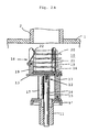
- FIG. 2A and 2B are explanatory views showing the details of the blocking apparatus according to the present invention.
- the base 11 is detachably mounted through a plate 9' on the movable member 9 and fixedly secured thereto in such a manner that it may be moved together with the movable member 9 as an integral unit thereof.
- the sliding member 12 is comprised of the first plate 13 and the sliding rod 14.
- the sliding rod 14 is supported in the above-mentioned base 11 so as to slidably move freely in the vertical direction in the drawing relative to the base 11. Further, the sliding member 12 is normally biased by the spring means 15 upwards relative to the base 11.
- the second plate 16 is placed on the upper surface of the above-mentioned plate 13 and fixedly supported by the struts 17 extending through the plate 13, relative to the base 11.
- the above-mentioned sliding member 12 is biased upwards by the spring means 15 so that the upper surface of the plate 13 is pressed against the plate 16.
- the above-mentioned sliding member 12 has a plug housing member 18 formed on the upper part thereof.
- the plug housing member 18 comprises the plate 16 and a plurality of struts 19 which stand upright around the plate 16. The arrangement is made such that a stack of a plurality of plugs 20 can be accommodated in the space defined by the struts 19 and held thereby.
- the above-mentioned plate 16 constitutes the bottom of the plug housing member 18.
- Each of the above-mentioned struts 19 has the slit 21 formed in the upper half portion thereof and in which the wire spring 22 is fitted. A portion of each of the wire springs 22 projects inwardly to hold resiliently the plugs 20 accommodated along the struts 19.
- Fig. 3 shows one embodiment of the plug according to the present invention.
- the plug 20 has such a shape as shown in Fig. 3, and is formed integrally of a plastic material.
- This plug comprises the disc-shaped body 23 whose diameter is slightly larger than the inside diameter of the branched pipe 2 to be blocked by the apparatus of the present invention.
- This disc-shaped body 23 has a plurality of cut-away portions 24 formed along the peripheral edge thereof at regular intervals so that each of the struts 19 of the plug housing member 18 of the blocking apparatus can be fitted loosely in each of the cut-away portions 24.
- the disc-shaped body 23 has a projecting portion 25 formed on the upper surface thereof and which has such a shape as to be fitted tightly in the inner surface of the branched pipe 2.
- the projecting portion 25 is formed by three pieces of strip-shaped ribs 26 assembled with one another as shown.
- the leading end of each of the ribs 26 projects outwardly so as to define the apex of a triangle thus forming tapered pressure contact portions 26a, 26b and 26c.
- the arrangement is made such that the extreme ends 26a, 26b and 26c are engageable with the inner surface of the branched pipe 2 and held tightly in the end of the opening of the branched pipe 2 formed in the main pipeline.
- the projecting portion 25 is formed by three pieces of ribs 26 assembled in a triangular shape, it may be formed in any desired shape provided that it has such a configuration as to be engageable with the inner surface of the branched pipe 2 at the branched portion through the action of a frictional force.
- Figs. 5A, 5B, 5C and 6 show further embodiments of the improved plug of the present invention.
- Plugs 31 and 31' are each formed integrally of a plastic material and comprise disc-shaped bodies 32 and 32', respectively, which have a diameter slightly larger than the inside diameter of the branched pipe 2 and also have cut-away portions 33 formed along the periphery of their bodies. Further, the cut-away portions 33 are formed to apply the above-mentioned blocking apparatus, it is not always indispensable to form them in terms of the function of the plug for use in blocking a branched pipe at a branched portion.
- each of the above-mentioned disc-shaped bodies 32 and 32' has a projecting portion 34 formed on the upper surface thereof and having such a shape as to be fitted tightly in the inner surface of a branched pipe.
- the projecting portion 34 has a substantially hexagonal shape in plan view.
- the projecting portion 34 has pressure contact portions 35 formed at positions corresponding to three apexes of the hexagon so that they can be engaged tightly with the inner surface of a branched pipe through the action of a frictional force exerted between them.
- each of the disc-shaped bodies 32 and 32' has a spherical, convex portion 36 formed in the central area of the lower surface thereof.
- each of the above-mentioned disc-shaped bodies 32 and 32' has a sealing member 37 of a elastomer such as, for example, rubber adhesively bonded onto the upper surface thereof and around the outer periphery of the projecting portion 34.
- the upper surface of the sealing member 37 is applied with an adhesive or binder as the case may be.
- Fig. 6 is a sectional view of another embodiment of the plug having an improved shape.
- This plug has a disc-shaped body 32' having a curved shape which is the same as that of the inner surface of a main pipeline in a branched portion to be blocked.
- the above-mentioned projecting portion 34 is formed on the curved surface on the opposite side of the convex portion.
- the plugs 20 are held by the wire springs 22, they are fixedly secured in the plug housing member 18 so that even when the blocking apparatus 10 is inclined or directed laterally or downwardly from its position shown in Figs. 1, 2A and 2B, according to the connecting position of the branched pipe 2, there is no risk of the plugs 20 dropping out from the plug housing member 18.
- the operating machine 3 with a plurality of plugs 20, 31 or 31' accommodated in the plug housing member 18 of the blocking apparatus 10 is inserted into the pipeline 1 and moved therethrough by operating the rod 6 or the like, while the operator is viewing the inside of the pipeline 1 by means of the television camera 8 to search for the opening of the branched pipe 2.
- the position of the operating machine 3 is adjusted by the operator while viewing the image on the screen of the television camera 8, and as occasion demands the turning unit 7 is turned so as to locate the blocking apparatus 10 at the position of the opening of the branched pipe 2.
- the leading ends of the struts 19 are first abutted against the leading end face of the branched pipe 2.
- the sliding member 12 cannot be moved upwards because the leading ends of the struts 19 are held by the leading end face of the branched pipe 2 around the opening.
- the base 11 is moved upwards relative to the sliding member 12 while compressing the spring means 15 so that the plate 16 fixedly secured to the base 11 is moved upwardly away from the plate 13.
- the group of plugs 20 resting on the plate 16 is pushed up along the struts 19.
- the plugs 20, 31 or 31' are moved upwards while spreading the wire springs 22 mounted on the struts 19, respectively.
- the projecting portion 25 or 34 of the uppermost plug is fitted in the inner surface of the opening of the branched pipe 2 so that the projecting portion is engaged with the inner surface of the branched pipe 2 and held thereby.
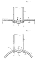
- the plug is held at the branched portion so as to cover the opening of the branched pipe 2 by the disc-shaped body. This condition is illustrated in Fig. 4.
- the uppermost plug remains to be held in the opening of the branched pipe 2, and the rest of the plugs accommodated in the plug housing member 18 will be moved down together with the sliding member 12.
- the opening of one of the branched pipes is blocked with the plug by the above-mentioned operation. Subsequently, the operating machine 3 is moved in turn to each of the openings of the branched pipes where the same operation is repeated, so that one piece of the plug is fitted in turn in each of the openings of branched pipes 2 thus blocking them. Therefore, by inserting the operating machine 3 once into the pipeline 1, the openings of branched pipes corresponding in number to the plugs accommodated in the plug housing member 18 can be blocked.
- the inner surface of the pipeline 1 is lined with a lining material according to a publicly known method.
- the condition of the pipeline which has been lined is illustrated in Figs. 7 and 8.
- the base 11 is removed from the movable member 9 mounted on the turning unit 7, and then a proper boring device is mounted onto the operating machine 3 in place of the blocking apparatus 10. Then, the operating machine 3 is inserted again into the lined pipeline. Subsequently, by driving the boring device, only the portions of the lining material adhesively bonded on the inner surface of the pipeline covering each of the openings of branched pipes are removed together with the plug 20, 31 or 31'. Thus, the branched pipes 2 are communicated with the pipeline 1.
- a boring device for use in boring the lining material covering the branched portions of the pipeline various kinds of constructions using a drill, a striker or a heating iron are proposed, and a proper one may be used as the borer.
- an EVA resin whose melting point is low should preferably be selected, because this resin can be readily bored, and can seal the periphery of holes formed in the lining material layer.
- a plug having a convex portion 36 formed in the central, lower surface thereof like the plugs 31 and 31' shown in Figs. 5 and 6 is used, when the inner surface of the lined pipeline is observed by the operator by means of the television camera 8, the projecting condition of the lining material layer 100 at the position of the opening of the branched pipe 2 can be easily confirmed through its image on the screen of the television camera. Therefore, it is convenient to use such a type of plug to find out the location of the opening.
- an enhanced adhesivity can be achieved between the lower surface and the lining material layer 100 so that leakage of fluid after the boring operation can be prevented.
- the leading end of the branched pipe 2 projects inwardly from the inner surface of the pipeline 1, and the end face thereof is generally planar.
- a plug having a flat-plate type disc-shaped body 32 as shown in Figs. 5A, 5B and 5C is used, and the branched portion can be blocked with this plug by engaging it with the inner surface of the branched pipe 2.
- the blocking apparatus of the present invention since when the inner surface of the pipeline 1 is lined with a lining material the openings of branched pipes in branched portions of the pipeline 1 have previously been blocked satisfactorily with plugs, there is no risk of an adhesive for bonding the lining material flowing into the branched pipe 2 resulting in formation of a thick solidified adhesive layer, which impedes boring operation, in the branched pipe 2. Therefore, in the subsequent process of boring the lining material covering the openings of branched pipes, it is sufficient to remove only the thin lining material and the plugs 20, 31 or 31' by boring, and so the lining material covering the openings can be bored easily in a short time.
- the plug housing member 18 can accommodate a plurality of plugs, when the operating machine 3 is once inserted into the pipeline 1, a plurality of openings of branched pipes can be blocked continuously with the plugs, and so the operational efficiency can be improved significantly.
- the plug according to the present invention can be fitted into the opening of a branched pipe very easily by a simple operation to block the branched portion of a pipeline, and after fitting there is almost no possibility of the plug dropping out of the plug housing member.
- the plug according to the present invention has a sealing member 37 bonded onto the upper surface thereof, even if the inner surface of the branched portion is somewhat irregular, the plug is pressed tightly against the inner surface along the irregularities through deformation of the sealing member 37, so that the branched portion can be sealed satisfactorily.
- the projecting portion 35 is of such a shape as to be fitted properly into the branched pipe, the branched portion can always be blocked surely with the plug.
- the position of the branched portion can be found out easily and exactly by viewing the image of the convex portion 36 formed on the lower surface of the disc-shaped body on the screen of the television camera, which offers convenience to the operation of boring the lining material covering the openings of branched portions.
Landscapes
- Engineering & Computer Science (AREA)
- Mechanical Engineering (AREA)
- General Engineering & Computer Science (AREA)
- Chemical & Material Sciences (AREA)
- Combustion & Propulsion (AREA)
- Pipe Accessories (AREA)
- Lining Or Joining Of Plastics Or The Like (AREA)
Claims (5)
- Gerät zum Verschließen von Öffnungen von Zweigrohren in Verzweigungsbereichen einer Rohrleitung (1), das vor dem Auskleiden der Innenfläche der die Verzweigungsbereiche aufweisenden Rohrleitung (1) verwendet wird, gekennzeichnet durch:
eine Basis (11), die auf einer drehbaren Einheit (7) derartig angebracht ist, daß sie radial bewegt werden kann, wobei die drehbare Einheit (7) auf einem in der Rohrleitung (1) beweglichen Arbeitsmaschinenrumpf (4) derartig angebracht ist, daß sie um die Längsachse der Rohrleitung (1) gedreht werden kann;
ein verschiebbares Teil (12), das aus einer in der Basis (11) verschiebbar gelagerten Stange (14) und einer ersten Platte (13) besteht;
eine Federeinrichtung (15), damit das verschiebbare Teil (12) nach oben relativ zur Basis (11) gedrückt wird;
eine zweite Platte (16), die mittels an der Basis (11) angeordneter unterer Streben (17) so an der Basis (11) fest angeordnet ist, daS sie durch die erste Platte (13) hindurchpaßt; und
ein Stöpselaufnahmeteil (18), das aus der zweiten Platte (16) und mehreren darauf befestigten oberen Streben (19) besteht,
wobei jede der oberen Streben (19) einen in ihrer oberen Hälfte ausgebildeten Schlitz (21) aufweist, wobei der Schlitz (21) eine darin eingepaßte Drahtfeder (22) aufweist, wobei ein Bereich der Drahtfeder (22) in das Stöpselaufnahmeteil (18) hineinragt, wobei die Anordnung so gestaltet ist, daS mehrere Stöpsel (20) durch die mehreren oberen Streben (19) und die zweite Platte (16) gehalten werden. - Stöpsel zum Verschließen jeder der Öffnungen von Zweigrohren während des Auskleidens der Innenfläche einer Rohrleitung mit Verzweigungsbereichen, der einen scheibenförmigen Körper aufweist, dessen Durchmesser etwas größer als der innere Durchmesser der jeweiligen Öffnungen der Zweigrohre in den Verzweigungsbereichen der Hauptleitung ist, wobei der scheibenförmige Körper einen auf einer Seite ausgebildeten vorspringenden Bereich aufweist und eine solche Form besitzt, daß er durch die Wirkung einer Reibungskraft zwischen ihnen in die Innenfläche des Zweigrohrs eingreifbar ist, wobei der scheibenförmige Körper ferner ausgeschnittene Bereiche aufweist, die an seinem Außenrand ausgebildet sind, wobei jeder der ausgeschnittenen Bereiche derart geformt ist, daß jede der Streben im Verschließgerät gemäß Anspruch 1 dort beweglich eingefügt werden kann, wobei der scheibenförmige Körper und der vorspringende Bereich einstückig aus einem Kunststoffmaterialmaterial ausgebildet werden.
- Stöpsel zum Verschließen jeder der Öffnungen von Zweigrohren nach Anspruch 2, wobei der scheibenförmige Körper einen gewölbten Bereich aufweist, der einstückig auf der Oberfläche auf der gegenüberliegenden Seite der mit dem vorspringenden Bereich versehenen Oberfläche ausgebildet ist.
- Stöpsel zum Verschließen jeder der Öffnungen von Zweigrohren nach Anspruch 2 oder 3, wobei der scheibenförmige Körper ein Dichtungsteil aufweist, das auf seine mit dem vorspringenden Bereich versehene Oberfläche aufgeklebt ist und sich rings um den vorspringenden Bereich erstreckt.
- Stöpsel zum Verschließen jeder der Öffnungen von Zweigrohren nach Anspruch 2 bis 4, wobei der scheibenförmige Körper eine gekrümmte Form aufweist, die dieselbe wie die der Innenfläche der Hauptleitung in jedem der mit den Stöpseln zu verschließenden Verzweigungsbereiche ist.
Applications Claiming Priority (1)
| Application Number | Priority Date | Filing Date | Title |
|---|---|---|---|
| PCT/JP1989/000013 WO1990007418A1 (fr) | 1989-01-06 | 1989-01-06 | Dispositif et instrument utilises pour revetir une conduite a embranchements |
Publications (3)
| Publication Number | Publication Date |
|---|---|
| EP0407575A1 EP0407575A1 (de) | 1991-01-16 |
| EP0407575A4 EP0407575A4 (en) | 1991-04-03 |
| EP0407575B1 true EP0407575B1 (de) | 1993-11-10 |
Family
ID=13958515
Family Applications (1)
| Application Number | Title | Priority Date | Filing Date |
|---|---|---|---|
| EP89901292A Expired - Lifetime EP0407575B1 (de) | 1989-01-06 | 1989-01-06 | Gerät und werkzeug zum auskleiden eines verzweigten rohres |
Country Status (5)
| Country | Link |
|---|---|
| EP (1) | EP0407575B1 (de) |
| CA (1) | CA2006117C (de) |
| DE (1) | DE68910683T2 (de) |
| DK (1) | DK210490A (de) |
| WO (1) | WO1990007418A1 (de) |
Families Citing this family (5)
| Publication number | Priority date | Publication date | Assignee | Title |
|---|---|---|---|---|
| JP2530552B2 (ja) * | 1993-03-23 | 1996-09-04 | 株式会社湘南合成樹脂製作所 | 枝管ライニング工法 |
| TW386936B (en) * | 1997-07-18 | 2000-04-11 | Get Inc | Making jig for a branch opening and pipe lining working method for a branch opening |
| GB9804353D0 (en) * | 1998-03-03 | 1998-04-22 | United Utilities Plc | Ferrule insertion |
| GB9805797D0 (en) * | 1998-03-18 | 1998-05-13 | Thames Water Utilities | Service connection |
| WO2010115290A1 (en) * | 2009-04-09 | 2010-10-14 | Aqua Rehab Inc. | Device and method for sealing a junction between a main pipe and a lateral pipe connected thereto |
Family Cites Families (1)
| Publication number | Priority date | Publication date | Assignee | Title |
|---|---|---|---|---|
| JPS6216127A (ja) * | 1985-07-15 | 1987-01-24 | Osaka Bosui Kensetsushiya:Kk | 枝管付管路内面のチユ−ブライニング工法 |
-
1989
- 1989-01-06 WO PCT/JP1989/000013 patent/WO1990007418A1/ja not_active Ceased
- 1989-01-06 DE DE68910683T patent/DE68910683T2/de not_active Expired - Fee Related
- 1989-01-06 EP EP89901292A patent/EP0407575B1/de not_active Expired - Lifetime
- 1989-12-20 CA CA002006117A patent/CA2006117C/en not_active Expired - Fee Related
-
1990
- 1990-09-03 DK DK210490A patent/DK210490A/da not_active Application Discontinuation
Also Published As
| Publication number | Publication date |
|---|---|
| DK210490D0 (da) | 1990-09-03 |
| EP0407575A4 (en) | 1991-04-03 |
| DE68910683D1 (de) | 1993-12-16 |
| CA2006117A1 (en) | 1990-07-06 |
| DK210490A (da) | 1990-09-03 |
| CA2006117C (en) | 1998-04-14 |
| EP0407575A1 (de) | 1991-01-16 |
| DE68910683T2 (de) | 1994-05-19 |
| WO1990007418A1 (fr) | 1990-07-12 |
Similar Documents
| Publication | Publication Date | Title |
|---|---|---|
| US5333649A (en) | Plug for blocking a branched pipe opening | |
| US6688337B2 (en) | Apparatus and method for the robotic repairing of an underground pipe junction with a flexible patch mechanism | |
| US6572306B2 (en) | Method of laying data cables and the like in underground pipes and pipe-cable combinations | |
| CA2275793C (en) | Testing of plumbing installations and plumbing tool | |
| US6206049B1 (en) | Apparatus and method for the robotic repairing of an underground pipe junction with removable heating element | |
| CA1323022C (en) | Coupling for concrete wall or floor mounting | |
| CA2150111A1 (en) | Improvements relating to the lining of pipelines and passageways | |
| CA2744902C (en) | Apparatus and method for connecting a saddle for a branch pipe to a main pipe | |
| US5971032A (en) | Apparatus and method for the robotic repairing of an underground pipe junction | |
| US20040037648A1 (en) | Apparatus and method for providing access to buried pipeline | |
| US6082411A (en) | Apparatus and method for the robotic repairing of an underground pipe junction | |
| AU2008247847A1 (en) | Self-contained keyhole weld fitting and method of use | |
| US20240077163A1 (en) | Lined mainline service sealing and reinforcement insert and method of installation thereof | |
| CA2205348C (en) | Apparatus and method for down hole fusing | |
| EP0407575A1 (de) | Gerät und werkzeug zum auskleiden eines verzweigten rohres | |
| US7674072B2 (en) | Connection between a lateral and main pipe and method for making same | |
| US5224742A (en) | Method for cutting off water in pipeline and structure of connection portion in pipeline | |
| WO2010115290A1 (en) | Device and method for sealing a junction between a main pipe and a lateral pipe connected thereto | |
| US20210071797A1 (en) | Apparatus and Method for Providing Access to Buried Pipeline | |
| US20010010781A1 (en) | Method of laying data cables and the like in underground pipes and pipe-cable combinations | |
| AU2917889A (en) | Apparatus and instrument used to line branched pipe | |
| JPH10299383A (ja) | ジャッキ管用装置 | |
| EP0891857B1 (de) | Vorrichtung zum Orten des Eintritts einer Abzweigrohrleitung und Rohrauskleidungsverfahren unter Verwendung dieser Vorrichtung | |
| JP2586959B2 (ja) | 管路の更新方法 | |
| US20200173158A1 (en) | Apparatus and Method for Providing Access to Buried Pipeline |
Legal Events
| Date | Code | Title | Description |
|---|---|---|---|
| PUAI | Public reference made under article 153(3) epc to a published international application that has entered the european phase |
Free format text: ORIGINAL CODE: 0009012 |
|
| AK | Designated contracting states |
Kind code of ref document: A1 Designated state(s): DE FR GB IT NL |
|
| 17P | Request for examination filed |
Effective date: 19901228 |
|
| A4 | Supplementary search report drawn up and despatched |
Effective date: 19910214 |
|
| AK | Designated contracting states |
Kind code of ref document: A4 Designated state(s): DE FR GB IT NL |
|
| 17Q | First examination report despatched |
Effective date: 19920615 |
|
| GRAA | (expected) grant |
Free format text: ORIGINAL CODE: 0009210 |
|
| AK | Designated contracting states |
Kind code of ref document: B1 Designated state(s): DE FR GB IT NL |
|
| REF | Corresponds to: |
Ref document number: 68910683 Country of ref document: DE Date of ref document: 19931216 |
|
| ITF | It: translation for a ep patent filed | ||
| ET | Fr: translation filed | ||
| PLBE | No opposition filed within time limit |
Free format text: ORIGINAL CODE: 0009261 |
|
| STAA | Information on the status of an ep patent application or granted ep patent |
Free format text: STATUS: NO OPPOSITION FILED WITHIN TIME LIMIT |
|
| 26N | No opposition filed | ||
| PGFP | Annual fee paid to national office [announced via postgrant information from national office to epo] |
Ref country code: GB Payment date: 19951228 Year of fee payment: 8 |
|
| PG25 | Lapsed in a contracting state [announced via postgrant information from national office to epo] |
Ref country code: GB Effective date: 19970106 |
|
| PGFP | Annual fee paid to national office [announced via postgrant information from national office to epo] |
Ref country code: NL Payment date: 19970130 Year of fee payment: 9 |
|
| GBPC | Gb: european patent ceased through non-payment of renewal fee |
Effective date: 19970106 |
|
| PG25 | Lapsed in a contracting state [announced via postgrant information from national office to epo] |
Ref country code: NL Free format text: LAPSE BECAUSE OF NON-PAYMENT OF DUE FEES Effective date: 19980801 |
|
| NLV4 | Nl: lapsed or anulled due to non-payment of the annual fee |
Effective date: 19980801 |
|
| PGFP | Annual fee paid to national office [announced via postgrant information from national office to epo] |
Ref country code: DE Payment date: 20010330 Year of fee payment: 13 |
|
| PG25 | Lapsed in a contracting state [announced via postgrant information from national office to epo] |
Ref country code: DE Free format text: LAPSE BECAUSE OF NON-PAYMENT OF DUE FEES Effective date: 20020801 |
|
| PG25 | Lapsed in a contracting state [announced via postgrant information from national office to epo] |
Ref country code: IT Free format text: LAPSE BECAUSE OF NON-PAYMENT OF DUE FEES;WARNING: LAPSES OF ITALIAN PATENTS WITH EFFECTIVE DATE BEFORE 2007 MAY HAVE OCCURRED AT ANY TIME BEFORE 2007. THE CORRECT EFFECTIVE DATE MAY BE DIFFERENT FROM THE ONE RECORDED. Effective date: 20050106 |
|
| PGFP | Annual fee paid to national office [announced via postgrant information from national office to epo] |
Ref country code: FR Payment date: 20080111 Year of fee payment: 20 |