EP0407302B1 - Verfahren zum Einstellen des Ventilspiels bei Brennkraftmaschinen und Einrichtung zur Durchführung dieses Verfahrens - Google Patents
Verfahren zum Einstellen des Ventilspiels bei Brennkraftmaschinen und Einrichtung zur Durchführung dieses Verfahrens Download PDFInfo
- Publication number
- EP0407302B1 EP0407302B1 EP19900401948 EP90401948A EP0407302B1 EP 0407302 B1 EP0407302 B1 EP 0407302B1 EP 19900401948 EP19900401948 EP 19900401948 EP 90401948 A EP90401948 A EP 90401948A EP 0407302 B1 EP0407302 B1 EP 0407302B1
- Authority
- EP
- European Patent Office
- Prior art keywords
- valve
- adjusting screw
- shim
- seat
- sensor
- Prior art date
- Legal status (The legal status is an assumption and is not a legal conclusion. Google has not performed a legal analysis and makes no representation as to the accuracy of the status listed.)
- Expired - Lifetime
Links
- 238000000034 method Methods 0.000 title claims description 32
- 238000002485 combustion reaction Methods 0.000 title claims description 6
- 238000006073 displacement reaction Methods 0.000 claims description 13
- 239000002033 PVDF binder Substances 0.000 claims description 5
- 230000010355 oscillation Effects 0.000 claims description 5
- 229920002981 polyvinylidene fluoride Polymers 0.000 claims description 5
- 238000005259 measurement Methods 0.000 claims description 4
- 230000009471 action Effects 0.000 claims description 3
- 239000000463 material Substances 0.000 claims 1
- 230000008569 process Effects 0.000 description 8
- 230000015654 memory Effects 0.000 description 5
- GNFTZDOKVXKIBK-UHFFFAOYSA-N 3-(2-methoxyethoxy)benzohydrazide Chemical compound COCCOC1=CC=CC(C(=O)NN)=C1 GNFTZDOKVXKIBK-UHFFFAOYSA-N 0.000 description 4
- FGUUSXIOTUKUDN-IBGZPJMESA-N C1(=CC=CC=C1)N1C2=C(NC([C@H](C1)NC=1OC(=NN=1)C1=CC=CC=C1)=O)C=CC=C2 Chemical compound C1(=CC=CC=C1)N1C2=C(NC([C@H](C1)NC=1OC(=NN=1)C1=CC=CC=C1)=O)C=CC=C2 FGUUSXIOTUKUDN-IBGZPJMESA-N 0.000 description 3
- PXHVJJICTQNCMI-UHFFFAOYSA-N Nickel Chemical compound [Ni] PXHVJJICTQNCMI-UHFFFAOYSA-N 0.000 description 2
- MCMNRKCIXSYSNV-UHFFFAOYSA-N Zirconium dioxide Chemical compound O=[Zr]=O MCMNRKCIXSYSNV-UHFFFAOYSA-N 0.000 description 2
- XAGFODPZIPBFFR-UHFFFAOYSA-N aluminium Chemical compound [Al] XAGFODPZIPBFFR-UHFFFAOYSA-N 0.000 description 2
- 229910052782 aluminium Inorganic materials 0.000 description 2
- PNEYBMLMFCGWSK-UHFFFAOYSA-N aluminium oxide Inorganic materials [O-2].[O-2].[O-2].[Al+3].[Al+3] PNEYBMLMFCGWSK-UHFFFAOYSA-N 0.000 description 2
- 238000001514 detection method Methods 0.000 description 2
- 230000006872 improvement Effects 0.000 description 2
- 125000006850 spacer group Chemical group 0.000 description 2
- 229910000831 Steel Inorganic materials 0.000 description 1
- 230000000903 blocking effect Effects 0.000 description 1
- 230000008859 change Effects 0.000 description 1
- 230000000295 complement effect Effects 0.000 description 1
- 230000006835 compression Effects 0.000 description 1
- 238000007906 compression Methods 0.000 description 1
- 238000010586 diagram Methods 0.000 description 1
- 230000000694 effects Effects 0.000 description 1
- 230000006870 function Effects 0.000 description 1
- 239000011810 insulating material Substances 0.000 description 1
- 239000012212 insulator Substances 0.000 description 1
- 238000004519 manufacturing process Methods 0.000 description 1
- 229910052759 nickel Inorganic materials 0.000 description 1
- 210000000056 organ Anatomy 0.000 description 1
- 230000009467 reduction Effects 0.000 description 1
- 230000000284 resting effect Effects 0.000 description 1
- 239000000523 sample Substances 0.000 description 1
- 239000011343 solid material Substances 0.000 description 1
- 239000010959 steel Substances 0.000 description 1
- WFKWXMTUELFFGS-UHFFFAOYSA-N tungsten Chemical compound [W] WFKWXMTUELFFGS-UHFFFAOYSA-N 0.000 description 1
- 229910052721 tungsten Inorganic materials 0.000 description 1
- 239000010937 tungsten Substances 0.000 description 1
- 239000012808 vapor phase Substances 0.000 description 1
- 238000004804 winding Methods 0.000 description 1
Images



Classifications
-
- F—MECHANICAL ENGINEERING; LIGHTING; HEATING; WEAPONS; BLASTING
- F01—MACHINES OR ENGINES IN GENERAL; ENGINE PLANTS IN GENERAL; STEAM ENGINES
- F01L—CYCLICALLY OPERATING VALVES FOR MACHINES OR ENGINES
- F01L1/00—Valve-gear or valve arrangements, e.g. lift-valve gear
- F01L1/20—Adjusting or compensating clearance
Definitions
- the present invention relates to a method of adjusting the play of the rocker arms of an internal combustion engine, and an apparatus for implementing this method.
- the assembly formed by the control cam, or the control member, the rocker assembly and the valve moves between two extreme positions, one or the valve is forced, under the action of the cam, to s '' move as far away from its seat (maximum lift position) and the other where the valve is pushed by a spring against its seat, and where there is, between the cam and the rocker assembly, or in the assembly to rocker arm, or between it and the valve, maximum play (maximum play position).
- This play which can be of the order of 0.1 to 0.3 mm, is essential to compensate for the effect of the differences in expansion, but it must remain within defined limits for proper operation of the engine.
- the operation is done in principle cold with a thickness gauge and the clearance is adjusted by modifying the length of one of the parts of the rocker assembly which comprises, for this purpose, a head mounted on an adjustment screw provided with a locking nut.
- This head when the clearance is zero, comes to bear, depending on the type of engine, on the cam, on the valve, or on another part of the rocker assembly.
- the operation when done manually, involves bringing the camshaft into the maximum play position, measuring the play, and, after loosening the lock nut, turning the screw at an angle suitable for bring the play to the desired limits, then tighten the lock nut.
- This apparatus includes a sensor capable of continuously grasping the displacements of the valve, this sensor is carried by a base on which is also fixed the motor for which it is a question of adjusting the valves, and it is provided with a sensor which comes to bear on a cup secured to the valve stem.
- the apparatus further comprises two tools, each driven by a motor, and arranged to drive in rotation one, the adjusting screw, and the other, the locking nut.
- the object of the present invention is to provide an automated process for adjusting valves which provides greater precision than that of the known method, and which makes it possible to use less expensive equipment.
- camshaft is meant here not only a camshaft of the current type but any device intended to mechanically move the valve according to a defined law.
- the same successive displacements of the adjusting screw are carried out as in DE-A-3 002 015, but the sensor does not determine the "zero point", where the valve rests on its seat, before the valve moves away from its seat. On the contrary, it determines this "zero point” during the reversing stroke, when the valve stops because it comes to rest on its seat and it is this "zero point" which serves as a point of start with the measurement of the angle of rotation which corresponds to the desired clearance.
- a wedge is a plate of solid material, bounded by two flat and parallel surfaces between them. Therefore, when the adjusting screw and the rocker element are in contact with the shim, the distance between them is fixed with precision, and cannot be affected by the relative position of the axes.
- the improvement in precision comes from the high quality of the wedge surfaces that can be obtained.
- the device for determining the position of the valve provided in step a) consists of the shim itself, the latter being associated with means for detecting the moment when it comes into simultaneous contact with the adjusting screw and said element of the rocker assembly, and the moment when said contact simultaneous ceases.
- the shim has an electrically insulating central part and two opposite conductive faces, the adjusting screw and said element of the rocker assembly with the same electrical potential, at least one of said opposite faces of the shim is brought to a different potential when it is not in contact with the adjustment screw or said element, and a sensor detects the moment when said face of the shim changes potential with respect to the adjustment screw and said element of the 'together.
- a shim comprising a layer of metallized polyvinylidene fluoride on its two faces, these being insulated from the outside by layers of insulating material. and the two metallized faces being connected to an electrical voltage sensor.
- provision may be made for the shim to be printed with oscillations in its plane, and the arrest of these oscillations is detected, which corresponds to the tightening of the shim between the adjusting screw and said element.
- the device for controlling the rotation of the adjusting screw comprises a stepping motor, and the instructions of the control member are stored and transmitted in the form of the number of steps of said motor.
- a quasi-continuous displacement sensor is used, it is advantageously provided that the latter is of the incremental type, and transmits in digital form the signals transmitted to the control unit.
- the accuracy can be improved with respect to the apparatus of document DE-A-30 02 015, by providing a feeler mounted movably on the support and provided with a button intended to come into contact with the seat of the valve or with a part which is rigidly linked to it, the sensor being linked to one of the feelers and its sensitive member being in contact with the other.
- the feelers are pivotally mounted on the support, a spring bearing on the support pushing one of the feelers to bring it into contact with the part on which its key must come to rest, and the other feeler being controlled by a jack mounted on the first support, the latter feeler being provided with an auxiliary member capable of driving the other feeler to put it out of action during assembly or disassembly of the support.
- This cylinder can also be controlled by the central control member, for example by means of a solenoid valve.
- FIG. 1 shows the division of the apparatus between three units: the central control member 1, the screwing device 2 of the adjusting screw and the locking nut, and the device 3 for detecting movements of the valve.
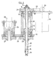
- FIG. 2 shows the detail of the screwing device.
- a frame 10 provided with means not shown for fixing relative to the engine block, carries two coaxial sleeves 11 and 12, which can rotate independently of each other relative to the frame 10 by means of ball bearings 13.
- the sleeves 11 and 12 are connected by pins 15 and 16 to a screwdriver rod 17, intended for driving the adjusting screw, and to a hexagonal socket 18, intended for driving the locking nut.
- the sheath 11 is rotated by a stepping motor 19, by means of pulleys 20, 21 and a toothed belt 22.
- the motor 19 thus drives the screwdriver 18, and, consequently, the adjusting screw 23 of a rocker arm 24.
- the sleeve 12 is rotated by a motor 25, which is a screwdriver motor, by means of a sleeve 26, two pulleys 27 and 28 and a toothed belt 29.
- the motor 25 is thus able to apply the torque necessary for tightening and loosening the locking nut 30 mounted on the adjusting screw 23.
- the springs 31-32 respectively push the screwdriver rod 17 and the sleeve 18 against the screw. adjustment 23 and the locking nut 30.
- the adjusting screw is carried by one end of the rocker arm 24, the other end of which comes into contact with a cam 33 of a camshaft 34 (FIG. 1). It is clear that the invention is not limited to such a provision.
- FIG. 3 shows the device intended to capture the movements of the valve.
- a button 40 is in contact with the upper cup 41 of the valve 42 which we want to adjust the rocker game.
- the key 40 is carried by a feeler 43 forming a lever, and articulated on an axis 44 carried by a support 45, itself provided with means 46 for fixing relative to the engine block.
- the end of the lever probe 43 carries another key 47, which is in contact with a flat key 48, located at the end of an incremental displacement sensor 49.
- This sensor is itself fixed on another lever 50 , pivotally mounted on an axis 51 carried by the same support 45.
- the end of the lever 50 opposite the sensor 49 carries a spherical key 52 which bears directly on a machined face of the cylinder head of the engine, as close as possible to the valve 42.
- a jack 53 pushes the lever 50 and thus ensures contact between the key 52 and the cylinder head.
- a spring 54 is supported on the support 45, and pushes the feeler-lever 43 to ensure the contact of the key 40 on the cup 41 of the valve.
- the feeler lever 50 is actually formed of parallel plates, held by spacers 55, 56.
- the spacer 56 passes under the feeler lever 43, so that when the cylinder 53 lifts the opposite end of the lever 50 upwards, according to FIG. 3, the lever 43 is also lifted and put out of contact with the valve cup, against the force of the spring 54, which allows the setting in place of the assembly without risking damaging the keys 40, 52.
- a motor fixed on a plate, is immobilized in a fixed position at the adjustment station.
- Slides fixed in the adjustment station, carry a frame 10 and a support 45. These are successively immobilized in line with all the valves arranged along the same line of the engine, for example the intake valves, for adjustment of the clearance that is specific to these valves.
- One or more other sets of slides, each carrying similar equipment, may be assigned to valves arranged along one or more other lines of the engine, for example the exhaust valves.
- the central control member 1 comprises a processor 61, whose functions have been explained above, and two memories 62, 63, which contain the numbers of steps of the motor 19, in steps e) and g) of the process.
- memories 62 and 63 can be parts of a single memory.
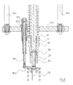
- Figures 5 to 8 relate to a preferred variant. Elements other than those in FIGS. 1 to 4 have reference numbers equal to or greater than 100.
- Figure 5 corresponds to the bottom left part of Figures 1 and 3 on a considerably enlarged scale, for clarity.
- a rocker arm 24, crossed by an adjustment screw 23 A screwdriver rod 17 is arranged to rotate the adjustment screw, and a hexagon socket 18 is intended to drive the nut blocking 30 of this adjusting screw.
- the figure also shows the stem of a valve 42 which, in the arrangement of the main patent, comes to bear directly on the end of the adjusting screw 23.
- a shim 100 is interposed between the adjustment rod 23 and the valve 42.
- This shim is mounted, fixed in rotation, on a support rod 101 mounted in a bearing 102, carried by a plate 103, itself connected to the frame by two balusters 104.
- a control lever 105 is mounted, fixed in rotation, on the shaft 101.
- the lever 105 has the form of a horizontal arm and it is articulated on the rod of an actuator 106, the body of which is itself articulated on a support carried by the plate 103.
- the position of the actuator 106 is shown in solid lines, or in dashed lines, lever 105 and shim 100 which correspond to the actuation of this shim, that is to say in the position visible in Figure 1. There is shown in broken lines the positions 105A and 100A of the lever and the shim in their inactive position, which allows the establishment of the valve.
- the cylinder 106 can be pneumatic or hydraulic, or electric.
- an electronic oscillator (not shown) to be interposed between the support rod 101 and the shim 100.
- This oscillator causes an oscillating movement of low angular amplitude around the axis of the support rod 101 in the proper plane of the hold.
- the electronics associated with the electromagnet which has a feedback winding, oscillates the system at its natural frequency (a few hundred Hertz). As soon as the wedge is hampered in its oscillating movement by the fact that it is tightened, the oscillations cease, which is instantly detected by the electronics and makes it possible to know precisely when the tightening starts or stops.
- FIG. 7 shows another method of detecting the tightening of the shim 100.
- This consists of a sandwich of three layers: a layer 110 of treated steel, a layer 111 of alumina, and a layer 112 of carbide of tungsten and nickel.
- the two end faces of the sandwich are electrically conductive, but the alumina layer constitutes an insulator.
- a very simple electrical circuit consisting of a voltage source 113, connected to the two layers conductive 110 and 112, and, in parallel, to a millivoltmeter 114. It is obvious that the indication of the millivoltmeter 114 corresponds to the voltage across the terminals of the source 113 as long as 110 and 111 are not in contact respectively with the valve 42 and with the adjusting screw 43. On the contrary, as soon as this contact takes place, the entire apparatus being metallic, the voltage across the terminals of the millivoltmeter 114 drops to zero.
- FIG. 4 shows a different embodiment of the shim 100.
- the two layers of aluminum 121, 122 are connected to a charge amplifier 125.
- polyvinylidene fluoride is piezoelectric. It is therefore understood that, as soon as the shim is compressed, a voltage appears at the terminals of the charge amplifier 125. It is within the reach of the skilled person to convert the voltages supplied at the terminals of the millivoltmeter 114 or at output of the charge amplifier 125 into control signals for implementing the method which has been described above.
Landscapes
- Engineering & Computer Science (AREA)
- Mechanical Engineering (AREA)
- General Engineering & Computer Science (AREA)
- Valve-Gear Or Valve Arrangements (AREA)
Claims (14)
- Ein Verfahren zum Einstellen des Spiels der Kipphebel der Ventile einer Brennkraftmaschine, die eine Gesamtheit von Kipphebeln aufweist mit zumindest einem Teil, von dem man die Länge mit Hilfe einer Stellschraube (23) versehen mit einer Sicherungsmutter (30) verändern kann, wobei dieses Verfahren die folgenden Schritte umfaßt,a) Montieren einer Vorrichtung (3) geeignet zum Bestimmen der Lage des Ventils bezüglich seines Sitzes auf dem Motor,b) Montieren einer Vorrichtung (2) zum Antreiben der Drehung der Stellschraube auf dem Motor,c) Bringen der Nockenwelle (34) in eine Lage, die normalerweise dem maximalen Spiel zwischen ihr und dem Ventil in Anlage auf seinem Sitz entspricht,d) Nehmen eines Zustandes, in dem sich das Ventil in Anlage auf seinem Sitz befindet, als Nullpunkt für Messungen der Vorrichtung zur Bestimmung der Lage des Ventils,e) Losschrauben der Sicherungsmutter,f) Antreiben der Drehung der Stellschraube bis sich das Ventil von seinem Sitz entfernt,g) Antreiben der Drehung der Stellschraube im entgegengesetzten Sinn, wobei diese Verstellung im umgekehrten Sinn über den Durchgang durch die ursprüngliche Position hinaus eine Drehung der Stellschraube um einen Winkel entsprechend dem gewünschten Spiel einschließt,h) Anziehen der Sicherungsmutter,dadurch gekennzeichnet, daß man im Verlauf des Schrittes g) mit Hilfe der Vorrichtung (3) zum Bestimmen der Lage des Ventils den Moment ermittelt, in dem dieses Ventil aufhört, sich in Richtung auf seinen Sitz zu bewegen und dieser Zeitpunkt den Ausgangspunkt der Winkelmessung der Drehung der Stellschraube entsprechend dem gewünschten Spiel bildet.
- Verfahren gemäß Anspruch 1, dadurch gekennzeichnet, daß- man vor dem Schritt f) eine präzise bekannte Unterlegplatte (100) zwischen die Stellschraube (23) und das Element (42) der Kipphebelgesamtheit gegen das die Stellschraube zur Anlage kommt einführt, in dem man die Unterlegplatte senkrecht zur Achse der Stellschraube anordnet,- man während des Schrittes g) der Stellschraube (23) eine ergänzende Drehung gibt, die dem gewünschten Spiel entspricht, vermindert um den Wert des Winkels, der der Dicke der Unterlegplatte (100) entspricht,- man die Unterlegplatte während des Schrittes (g) wegnimmt.
- Verfahren gemäß Anspruch 2, dadurch gekennzeichnet, daß die Vorrichtung zum Bestimmen der Lage des Ventils, die im Schritt a) vorgesehen ist, von der Unterlegplatte (100) selbst gebildet ist, wobei diese mit Mitteln (114, 125) verbunden ist, um den Moment, wo sie zugleich in Kontakt mit der Stellschraube und dem Element der Ripphebelgesamtheit kommt, und den Moment, in dem dieser Kontakt aufhört, ausfindig zu machen.
- Verfahren gemäß Anspruch 3, dadurch gekennzeichnet, daß die Unterlegplatte einen mittleren elektrisch isolierenden Teil und zwei gegenüberliegende leitende Flächen (110, 112) hat, die Stellschraube (23) und das Element (42) der Kipphebelgesamtheit am selben elektrischen Potential liegen, zumindest eine der gegenüberliegenden Seiten der Unterlegplatte an einem verschiedenen Potential anliegt, wenn sie nicht in Kontakt mit der Stellschraube oder dem Element ist, und eine Meßzelle (114) den Moment detektiert, in dem die Fläche der Unterlegplatte das Potential bezüglich der Stellschraube und dem Element der Gesamtheit ändert.
- Verfahren gemäß Anspruch 3, dadurch gekennzeichnet, daß im Inneren der Unterlegplatte ein piezoelektrisches Element (121) eingeschlossen ist, welches erlaubt, eine auf die Unterlegplatte ausgeübte Druckkraft zu detektieren.
- Verfahren gemäß Anspruch 5, dadurch gekennzeichnet, daß man eine Unterlegplatte gebraucht, die eine Schicht von Polyvinylidenfluorid (121) aufweist, die auf ihren beiden Seiten (120, 122) metallisiert ist, welche von der Umgebung durch Schichten aus isolierendem Material (123, 124) isoliert sind und die beiden metallisierten Flächen mit einem Ladungsverstärker (125) verbunden sind.
- Verfahren gemäß Anspruch 3, dadurch gekennzeichnet, daß man der Unterlegplatte Schwingungen in ihrer Ebene aufgibt, und daß man das Aufhören dieser Schwingungen detektiert, daß mit dem Einklemmen der Unterlegplatte zwischen der Stellschraube und dem Element korrespondiert.
- Verfahren gemäß einem der Ansprüche 1 bis 7, dadurch gekennzeichnet, daß das Element der Ripphebelgesamtheit vom Endstück des Ventils gebildet ist.
- Apparatur zum Durchführen des Verfahrens gemäß einem der Ansprüche 1 bis 8, mit- einer Vorrichtung, die einen Meßfühler (49) aufweist, der geeignet ist, den Nullpunkt zu detektieren, in dem das Ventil (42) in Berührung mit seinem Sitz gelangt,- einer Vorrichtung (2) zum Antreiben der Drehung der Stellschraube,- wobei diese Apparatur dadurch gekennzeichnet ist, daß sie überdies ein zentrales Steuerorgan (1) verbunden mit der Vorrichtung zum Antreiben der Drehung und mit dem Meßfühler aufweist, wobei dieses Organ vorgesehen ist, im Schritt f) die Drehung der Stellschraube in einem ersten Sinn folgend einem ersten Winkel, der zuvor gespeichert zu steuern, dann im Schritt g) im entgegengesetzten Sinn bis zum Detektieren des Anhaltens der Bewegung des Ventils mit Hilfe von Signalen abgegeben vom Meßfühler zu steuern, und schließlich, nach der Detektion des Anhaltens, einem zweiten Winkel folgend, entsprechend dem Spiel und vorheriger Speicherung zu steuern, um Schritt g) zu verwirklichen.
- Apparatur gemäß Anspruch 9, dadurch gekennzeichnet, daß die Vorrichtung zum Antreiben der Drehung der Stellschraube einen Schrittmotor (19) aufweist und die Befehle des Steuerorgans gespeichert sind und in Form einer Anzahl von Schritten des Motors übertragen werden.
- Apparatur gemäß einem der Ansprüche 9 oder 10, und in der der Meßfühler geeignet zur Bestimmung des Nullpunktes ein Bewegungsfühler ist, der geeignet ist, auf quasi-kontinuierliche Weise Verschiebungen des Ventils bezüglich seines Sitzes aufzunehmen, dadurch gekennzeichnet, daß der Meßfühler vom inkrementalen Typ ist und in numerischer Form die zum Steuerorgan übertragenen Signale ausgibt.
- Apparatur gemäß einem der Ansprüche 9 oder 10, und in der der Meßfühler geeignet zum Detektieren des Nullpunktes ein Bewegungsfühler ist geeignet zum Aufnehmen auf quasi-kontinuierliche Art der Verschiebungen des Ventils bezüglich seines Sitzes oder gemäß Anspruch 11, mit- einem Träger (45), der im Stande ist, in einer festgelegten Position bezüglich der zu kontrollierenden Brennkraftmaschine immobilisiert zu werden,- einem Taststift (43), der beweglich auf dem Träger angebracht und mit einem Tastkopf (40) versehen ist, der in Kontakt mit dem Ventil (42) oder mit einem damit fest verbundenen Teil (41) gelangen soll, und- einem Meßfühler, der empfindlich für die Verlagerung des Taststiftes ist,dadurch gekennzeichnet, daß sie überdies
- einen Taststift (50) aufweist, der beweglich auf dem Träger angeordnet und mit einem Tastkopf (52) versehen ist, der die Berührung mit dem Sitz des Ventiles oder mit einem Teil, das mit diesem starr verbunden ist, kommen soll, wobei der Meßfühler (49) mit einem der Taststifte verbunden ist, wovon das empfindliche Organ (48) in Kontakt mit dem anderen ist. - Apparatur gemäß Anspruch 12, dadurch gekennzeichnet, daß die Taststifte schwenkbar auf dem Träger angebracht sind, wobei eine Feder (54) an dem Träger anliegt, wobei sie gegen einen der Taststifte drückt, um ihn in Berührung mit dem Teil zu halten, auf dem sein Tastkopf in Anlage kommen soll, und wobei der andere Taststift von einem Zylinder (53) angetrieben ist, der auf dem ersten Träger angebracht ist, wobei dieser letztere Taststift mit einem Hilfsorgan (56) versehen ist, welches geeignet ist, den anderen Taststift mitzunehmen, um ihn während der Montage oder der Demontage des Trägers wirkungslos zu machen.
- Apparatur gemäß Anspruch 13, dadurch gekennzeichnet, daß der Zylinder (53) ebenfalls von dem zentralen Steuerorgan angetrieben ist.
Applications Claiming Priority (4)
| Application Number | Priority Date | Filing Date | Title |
|---|---|---|---|
| FR8909102A FR2649444B1 (fr) | 1989-07-06 | 1989-07-06 | Procede de reglage du jeu des culbuteurs d'un moteur a combustion interne, et appareillage pour la mise en oeuvre de ce procede |
| FR8909102 | 1989-07-06 | ||
| FR9000327 | 1990-01-12 | ||
| FR9000327A FR2657118B1 (fr) | 1989-07-06 | 1990-01-12 | Procede de reglage du jeu des culbuteurs d'un moteur a combustion interne, et appareillage pour la mise en óoeuvre de ce procede. |
Publications (2)
| Publication Number | Publication Date |
|---|---|
| EP0407302A1 EP0407302A1 (de) | 1991-01-09 |
| EP0407302B1 true EP0407302B1 (de) | 1993-04-21 |
Family
ID=26227455
Family Applications (1)
| Application Number | Title | Priority Date | Filing Date |
|---|---|---|---|
| EP19900401948 Expired - Lifetime EP0407302B1 (de) | 1989-07-06 | 1990-07-05 | Verfahren zum Einstellen des Ventilspiels bei Brennkraftmaschinen und Einrichtung zur Durchführung dieses Verfahrens |
Country Status (4)
| Country | Link |
|---|---|
| EP (1) | EP0407302B1 (de) |
| DE (1) | DE69001401T2 (de) |
| ES (1) | ES2041513T3 (de) |
| FR (1) | FR2657118B1 (de) |
Families Citing this family (5)
| Publication number | Priority date | Publication date | Assignee | Title |
|---|---|---|---|---|
| IT1253075B (it) * | 1991-09-20 | 1995-07-10 | Giuliano Spaggiari | Dispositivo per tarare automaticamente i rubinetti di regolazione della portata del gas per bruciatori di cucine a gas ad uso domestico |
| GB0021181D0 (en) * | 2000-08-30 | 2000-10-18 | Perkins Engines Co Ltd | Method for automatically setting valve clearances setting valve clearances in an internal combustion engine |
| US6471299B2 (en) | 2001-02-15 | 2002-10-29 | Caterpillar Inc | Mooring device for maintaining a dump body in a raised position |
| DE10150786C2 (de) * | 2001-10-15 | 2003-08-07 | Siemens Ag | Verfahren und Vorrichtung zum automatischen Einstellen von Injektoren |
| CN108180048B (zh) * | 2017-12-15 | 2019-08-27 | 潍柴动力股份有限公司 | 一种气门间隙调整装置 |
Family Cites Families (3)
| Publication number | Priority date | Publication date | Assignee | Title |
|---|---|---|---|---|
| JPS5838604B2 (ja) * | 1979-01-24 | 1983-08-24 | トヨタ自動車株式会社 | 内燃機関のバルブクリアランス調整、バルブタイミング検査方法 |
| JPS571950A (en) * | 1980-06-05 | 1982-01-07 | Toyota Motor Corp | Method and device for judging abnormal state of moving valve system of engine |
| DE3635929A1 (de) * | 1986-10-22 | 1988-05-05 | Daimler Benz Ag | Verfahren zum einstellen des ventilspiels eines ventils in einer brennkraftmaschine |
-
1990
- 1990-01-12 FR FR9000327A patent/FR2657118B1/fr not_active Expired - Lifetime
- 1990-07-05 ES ES90401948T patent/ES2041513T3/es not_active Expired - Lifetime
- 1990-07-05 DE DE1990601401 patent/DE69001401T2/de not_active Expired - Fee Related
- 1990-07-05 EP EP19900401948 patent/EP0407302B1/de not_active Expired - Lifetime
Also Published As
| Publication number | Publication date |
|---|---|
| FR2657118A1 (fr) | 1991-07-19 |
| DE69001401T2 (de) | 1993-07-29 |
| EP0407302A1 (de) | 1991-01-09 |
| ES2041513T3 (es) | 1993-11-16 |
| FR2657118B1 (fr) | 1992-05-29 |
| DE69001401D1 (de) | 1993-05-27 |
Similar Documents
| Publication | Publication Date | Title |
|---|---|---|
| EP0407302B1 (de) | Verfahren zum Einstellen des Ventilspiels bei Brennkraftmaschinen und Einrichtung zur Durchführung dieses Verfahrens | |
| EP1666833B1 (de) | Motorisierter und orientierbarer Messkopf | |
| FR2534682A1 (fr) | Tete de palpeur pour la verification de dimensions lineaires | |
| FR2828733A1 (fr) | Appareil d'essai d'engrenage a deux flancs | |
| WO2005077585A1 (fr) | Outil de serrage, en particulier pince a souder, avec un systeme de compensation | |
| CA2326648C (fr) | Procede pour mesurer par ultrasons la tension residuelle d'une barre de precontrainte | |
| FR2460182A1 (fr) | Dispositif permettant d'usiner des cames avec precision, et avec une vitesse de coupe constante | |
| EP0916934A1 (de) | Numerischer Kraftsensor mit einer elastisch verformbaren Messzelle und Verfahren zur direkten Messung einer angewendeten Kraft | |
| FR1464441A (fr) | Réglage mécanique du coulisseau d'une presse | |
| JPS5838604B2 (ja) | 内燃機関のバルブクリアランス調整、バルブタイミング検査方法 | |
| EP0177744B1 (de) | Messkopf zur Diametermessung von zylindrischen Objekten | |
| FR2649444A1 (fr) | Procede de reglage du jeu des culbuteurs d'un moteur a combustion interne, et appareillage pour la mise en oeuvre de ce procede | |
| EP0767366A1 (de) | Rotierender Spindelantrieb mit Schnellspannvorrichtung und Maschine damit | |
| EP1456555B1 (de) | Elektromechanische bremsanlage und verfahren zu deren steuerung | |
| EP4357087B1 (de) | Greifer | |
| EP0966049B1 (de) | Piezoelektrischer Motor mit integriertem Positionssensor | |
| EP0532377A1 (de) | Winkeleinstellungsvorrichtung für die Nockenwelle einer Brennkraftmaschine und dazugehörige Nockenwelle | |
| EP0918264B9 (de) | Positionseinstellvorrichtung für eine auf einem Uhrwerkhemmungsanker montierte Palette | |
| JPS628609B2 (de) | ||
| EP1592534B1 (de) | Vorrichtung zum schleifen von ophthalmischen linsen mit verbessertem mittel zum festklemmen des glasrohlings zum schleifen | |
| FR2632972A1 (fr) | Dispositif pour le durcissement de pieces par refusion | |
| EP4426526B1 (de) | Greifer | |
| EP4169779B1 (de) | Handbremssystem | |
| FR2571290A1 (fr) | Machine de fraisage et polissage d'un chant d'une piece en materiau dur | |
| CH625614A5 (de) |
Legal Events
| Date | Code | Title | Description |
|---|---|---|---|
| PUAI | Public reference made under article 153(3) epc to a published international application that has entered the european phase |
Free format text: ORIGINAL CODE: 0009012 |
|
| AK | Designated contracting states |
Kind code of ref document: A1 Designated state(s): DE ES FR GB IT |
|
| 17P | Request for examination filed |
Effective date: 19910610 |
|
| 17Q | First examination report despatched |
Effective date: 19911125 |
|
| GRAA | (expected) grant |
Free format text: ORIGINAL CODE: 0009210 |
|
| AK | Designated contracting states |
Kind code of ref document: B1 Designated state(s): DE ES FR GB IT |
|
| GBT | Gb: translation of ep patent filed (gb section 77(6)(a)/1977) |
Effective date: 19930427 |
|
| REF | Corresponds to: |
Ref document number: 69001401 Country of ref document: DE Date of ref document: 19930527 |
|
| ITF | It: translation for a ep patent filed | ||
| REG | Reference to a national code |
Ref country code: ES Ref legal event code: FG2A Ref document number: 2041513 Country of ref document: ES Kind code of ref document: T3 |
|
| PLBE | No opposition filed within time limit |
Free format text: ORIGINAL CODE: 0009261 |
|
| STAA | Information on the status of an ep patent application or granted ep patent |
Free format text: STATUS: NO OPPOSITION FILED WITHIN TIME LIMIT |
|
| 26N | No opposition filed | ||
| REG | Reference to a national code |
Ref country code: GB Ref legal event code: IF02 |
|
| PGFP | Annual fee paid to national office [announced via postgrant information from national office to epo] |
Ref country code: GB Payment date: 20030704 Year of fee payment: 14 |
|
| PGFP | Annual fee paid to national office [announced via postgrant information from national office to epo] |
Ref country code: DE Payment date: 20030710 Year of fee payment: 14 |
|
| PGFP | Annual fee paid to national office [announced via postgrant information from national office to epo] |
Ref country code: FR Payment date: 20030711 Year of fee payment: 14 |
|
| PGFP | Annual fee paid to national office [announced via postgrant information from national office to epo] |
Ref country code: ES Payment date: 20030717 Year of fee payment: 14 |
|
| PG25 | Lapsed in a contracting state [announced via postgrant information from national office to epo] |
Ref country code: GB Free format text: LAPSE BECAUSE OF NON-PAYMENT OF DUE FEES Effective date: 20040705 |
|
| PG25 | Lapsed in a contracting state [announced via postgrant information from national office to epo] |
Ref country code: ES Free format text: LAPSE BECAUSE OF NON-PAYMENT OF DUE FEES Effective date: 20040706 |
|
| PG25 | Lapsed in a contracting state [announced via postgrant information from national office to epo] |
Ref country code: DE Free format text: LAPSE BECAUSE OF NON-PAYMENT OF DUE FEES Effective date: 20050201 |
|
| GBPC | Gb: european patent ceased through non-payment of renewal fee |
Effective date: 20040705 |
|
| PG25 | Lapsed in a contracting state [announced via postgrant information from national office to epo] |
Ref country code: FR Free format text: LAPSE BECAUSE OF NON-PAYMENT OF DUE FEES Effective date: 20050331 |
|
| REG | Reference to a national code |
Ref country code: FR Ref legal event code: ST |
|
| PG25 | Lapsed in a contracting state [announced via postgrant information from national office to epo] |
Ref country code: IT Free format text: LAPSE BECAUSE OF NON-PAYMENT OF DUE FEES;WARNING: LAPSES OF ITALIAN PATENTS WITH EFFECTIVE DATE BEFORE 2007 MAY HAVE OCCURRED AT ANY TIME BEFORE 2007. THE CORRECT EFFECTIVE DATE MAY BE DIFFERENT FROM THE ONE RECORDED. Effective date: 20050705 |
|
| REG | Reference to a national code |
Ref country code: ES Ref legal event code: FD2A Effective date: 20040706 |