EP0407302A1 - Method for adjusting the valve play in an internal combustion engine and device for implementing this method - Google Patents
Method for adjusting the valve play in an internal combustion engine and device for implementing this method Download PDFInfo
- Publication number
- EP0407302A1 EP0407302A1 EP90401948A EP90401948A EP0407302A1 EP 0407302 A1 EP0407302 A1 EP 0407302A1 EP 90401948 A EP90401948 A EP 90401948A EP 90401948 A EP90401948 A EP 90401948A EP 0407302 A1 EP0407302 A1 EP 0407302A1
- Authority
- EP
- European Patent Office
- Prior art keywords
- valve
- adjusting screw
- shim
- rotation
- seat
- Prior art date
- Legal status (The legal status is an assumption and is not a legal conclusion. Google has not performed a legal analysis and makes no representation as to the accuracy of the status listed.)
- Granted
Links
Images


Classifications
-
- F—MECHANICAL ENGINEERING; LIGHTING; HEATING; WEAPONS; BLASTING
- F01—MACHINES OR ENGINES IN GENERAL; ENGINE PLANTS IN GENERAL; STEAM ENGINES
- F01L—CYCLICALLY OPERATING VALVES FOR MACHINES OR ENGINES
- F01L1/00—Valve-gear or valve arrangements, e.g. lift-valve gear
- F01L1/20—Adjusting or compensating clearance
Definitions
- the present invention relates to a method of adjusting the play of the rocker arms of an internal combustion engine, and an apparatus for implementing this method.
- the assembly formed by the control cam, or the control member, of rocker assembly and the valve moves between two extreme positions, one where the valve is forced, under the action of the cam, to s '' move as far away from its seat (maximum lifting position) and the other where the valve is pushed by a spring against its seat, and where there is, between the cam and the rocker clearance, or in the rocker assembly , or between it and the valve, maximum play (maximum play position).
- This play which can be of the order of 0.1 to 0.3 mm, is essential to compensate for the effect of the differences in expansion, but it must remain within defined limits for proper operation of the engine.
- the operation is done in principle cold with a thickness gauge and the clearance is adjusted by modifying the length of one of the parts of the rocker assembly which comprises, for this purpose, a head mounted on an adjustment screw provided with a locking nut.
- This head when the clearance is zero, comes to bear, depending on the type of engine, on the cam, on the valve, or on another part of the rocker assembly.
- the operation when done manually, involves bringing the camshaft into the maximum play position, measuring the play, and, after loosening the lock nut, turning the screw at an angle suitable for bring the play to the desired limits, then tighten the lock nut.
- Document DE-A-30 02 015 has proposed a process which lends itself to automation, and which comprises the following operations: a detector sensitive to the position of the valve relative to the engine block, that is to say to the seat of the valve, is installed, and a device for controlling the rotation of the adjusting screw, - after having released the locking nut and brought the rocker arm to the position which corresponds to the maximum clearance, the detector locates the zero point, where the valve rests on its seat, - the adjustment screw is advanced until the sensor signals that the valve is lifted by a height x1 on its seat, - the adjustment screw is moved back until the sensor signals that the valve is lifted by a height x2, between O and x, and - the adjustment screw is moved back by rotation by an angle corresponding to the distance x2 + x3, x3 being the desired clearance.
- This apparatus includes a sensor capable of continuously grasping the displacements of the valve, this sensor is carried by a base on which is also fixed the motor for which it is a question of adjusting the valves, and it is provided with a sensor which comes to bear on a cup secured to the valve stem.
- the apparatus further comprises two tools, each driven by a motor, and arranged to drive in rotation one, the adjusting screw, and the other, the locking nut.
- the object of the present invention is to provide an automated process for adjusting valves which provides greater precision than that of the known method, and which makes it possible to use less expensive equipment.
- camshaft is meant here not only a camshaft of the current type but any device intended to mechanically move the valve according to a defined law.
- the same successive displacements of the adjusting screw are carried out as in DE-A-3 002 015, but the sensor does not determine the "zero point", where the valve rests on its seat, before the valve moves away from its seat. On the contrary, it determines this "zero point” during the reversing stroke, when the valve stops because it comes to rest on its seat and it is this "zero point" which serves as a point of start with the measurement of the angle of rotation which corresponds to the desired clearance.
- a shim of known thickness is introduced with precision between the adjustment screw and the element of the rocker assembly against which said adjustment screw comes to bear, by placing said shim perpendicular to the 'axis of the adjusting screw, in step g), the adjusting screw is printed with a complementary rotation which corresponds to the desired clearance, minus the angular value which corresponds to the thickness of the shim, - and the shim is removed after step g).
- a wedge is a plate of solid material, bounded by two flat and parallel surfaces between them. Therefore, when the adjusting screw and the rocker element are in contact with the shim, the distance between them is fixed with precision, and cannot be affected by the relative position of the axes.
- the improvement in precision comes from the high quality of the wedge surfaces that can be obtained.
- the device for determining the position of the valve provided in step a) consists of the shim itself, the latter being associated with means for detecting the moment when it comes into simultaneous contact with the adjusting screw and said element of the rocker assembly, and the moment when said contact simultaneous ceases.
- the shim has an electrically insulating central part and two opposite conductive faces, the adjusting screw and said element of the rocker assembly with the same electrical potential, at least one of said opposite faces of the shim is brought to a different potential when it is not in contact with the adjusting screw or said element, and a sensor detects the moment when said face of the shim changes potential with respect to the adjusting screw and said element of the 'together.
- a shim comprising a layer of metallized polyvinylidene fluoride on its two faces, these being insulated from the outside by layers of insulating material. and the two metallized faces being connected to an electrical voltage sensor.
- provision may be made for the shim to be printed with oscillations in its plane, and the arrest of these oscillations is detected, which corresponds to the tightening of the shim between the adjusting screw and said element.
- the invention also provides an apparatus for implementing the above method, and which comprises: - a device, comprising a sensor capable of detecting the zero point, where the valve comes into contact with its seat, - a device for controlling the rotation of the adjusting screw, this device being characterized in that it further comprises a central control member, connected to the rotation control device and to the sensor, this member being arranged to control in step e) the rotation of the adjusting screw in a first direction along a first angle previously stored in memory, then, in step f), in the opposite direction until detection using the signals emitted by the sensor, of the stop of the movement of the valve, and then, after said stop detection, at a second angle, corresponding to the game, and previously stored in memory, to carry out step g).
- the device for controlling the rotation of the adjusting screw comprises a stepping motor, and the instructions of the control member are stored and transmitted in the form of the number of steps of said motor.
- a quasi-continuous displacement sensor is used, it is advantageously provided that the latter is of the incremental type, and transmits in digital form the signals transmitted to the control unit.
- the accuracy can be improved with respect to the apparatus of document DE-A-30 02 015, by providing a feeler mounted movably on the support and provided with a button intended to come into contact with the seat of the valve or with a part which is rigidly linked to it, the sensor being linked to one of the feelers and its sensitive member being in contact with the other.
- the feelers are pivotally mounted on the support, a spring bearing on the support pushing one of the feelers to bring it into contact with the part on which its key must come to rest, and the other feeler being controlled by a jack mounted on the first support, the latter feeler being provided with an auxiliary member capable of driving the other feeler to put it out of action during assembly or disassembly of the support.
- This cylinder can also be controlled by the central control member, for example by means of a solenoid valve.
- FIG. 1 shows the division of the apparatus between three units: the central control member 1, the screwing device 2 of the adjusting screw and the locking nut, and the device 3 for detecting movements of the valve.
- FIG. 2 shows the detail of the screwing device.
- a frame 10 provided with means not shown for fixing relative to the engine block, carries two coaxial sleeves 11 and 12, which can rotate independently of each other relative to the frame 10 by means of ball bearings 13.
- the sleeves 11 and 12 are connected by pins 15 and 16 to a screwdriver rod 17, intended for driving the adjusting screw and a hexagonal socket 18, intended for driving the locking nut.
- the sheath 11 is rotated by a stepping motor 19, by means of pulleys 20, 21 and a toothed belt 22.
- the motor 19 thus drives the screwdriver 18, and, consequently, the adjusting screw 23 of a rocker arm 24.
- the sleeve 12 is rotated by a motor 25, which is a screwdriver motor, by means of a sleeve 26, two pulleys 27 and 28 and a toothed belt 29.
- the motor 25 is thus able to apply the torque necessary for tightening and loosening the locking nut 30 mounted on the adjusting screw 23.
- the springs 31-32 respectively push the screwdriver rod 17 and the socket 18 against the adjustment 23 and the locking nut 30.
- the adjusting screw is carried by one end of the rocker arm 24, the other end of which comes into contact with a cam 33 of a camshaft 34 (FIG. 1). It is clear that the invention is not limited to such a provision.
- FIG. 3 shows the device intended to capture the movements of the valve.
- a button 40 is in contact with the upper cup 41 of the valve 42 which we want to adjust the rocker game.
- the key 40 is carried by a feeler 43 forming a lever, and articulated on an axis 44 carried by a support 45, itself provided with means 46 for fixing relative to the engine block.
- the end of the lever probe 43 carries another key 47, which is in contact with a flat key 48, located at the end of an incremental displacement sensor 49.
- This sensor is itself fixed on another lever 50 , pivotally mounted on an axis 51 carried by the same support 45.
- the end of the lever 50 opposite the sensor 49 carries a spherical key 52 which bears directly on a machined face of the cylinder head of the engine, as close as possible to the valve 42.
- a jack 53 pushes the lever 50 and thus ensures contact between the key 52 and the cylinder head.
- a spring 54 is supported on the support 45, and pushes the feeler-lever 43 to ensure the contact of the key 40 on the cup 41 of the valve.
- the feeler lever 50 is actually formed of parallel plates, held by spacers 55, 56.
- the spacer 56 passes under the feeler lever 43, so that when the cylinder 53 lifts the opposite end of the lever 50 upwards, according to FIG. 3, the lever 43 is also lifted and put out of contact with the valve cup, against the force of the spring 54, which allows the setting in place of the assembly without risking damaging the keys 40, 52.
- a motor fixed on a plate, is immobilized in a fixed position at the adjustment station.
- Slides fixed in the adjustment station, carry a frame 10 and a support 45. These are successively immobilized in line with all the valves arranged along the same line of the engine, for example the intake valves, for adjustment of the clearance that is specific to these valves.
- One or more other sets of slides, each carrying similar equipment, may be assigned to valves arranged along one or more other lines of the engine, for example the exhaust valves.
- the central control member 1 comprises a processor 61, whose functions have been explained above, and two memories 62, 63, which contain the numbers of steps of the motor 19, in steps e) and g) of the process.
- memories 62 and 63 can be parts of a single memory.
- FIGS. 5 to 8 relate to a preferred variant
- the elements different from those of FIGS. 1 to 4 bear reference numbers equal to or greater than 100.
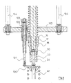
- Figure 5 corresponds to the bottom left part of Figures 1 and 3 on a considerably enlarged scale, for clarity.
- a rocker arm 24, crossed by an adjustment screw 23 A screwdriver rod 17 is arranged to rotate the adjustment screw, and a hexagon socket 18 is intended to drive the nut blocking 30 of this adjusting screw.
- the figure also shows the stem of a valve 42 which, in the arrangement of the main patent, comes to bear directly on the end of the adjusting screw 23.
- a shim 100 is interposed between the adjustment rod 23 and the valve 42.
- This shim is mounted, fixed in rotation, on a support rod 101 mounted in a bearing 102, carried by a plate 103, itself connected to the frame by two balusters 104.
- a control lever 105 is mounted, fixed in rotation, on the shaft 101.
- the lever 105 has the form of a horizontal arm and it is articulated on the rod of an actuator 106, the body of which is itself articulated on a support carried by the plate 103.
- the position of the actuator 106 is shown in solid lines, or in dashed lines, lever 105 and shim 100 which correspond to the actuation of this shim, that is to say in the position visible in FIG. 1.
- the positions 105A and 100A of the lever and of the shim in their inactive position, which allows the establishment of the valve.
- the cylinder 106 can be pneumatic or hydraulic, or electric.
- an electronic oscillator (not shown) to be interposed between the support rod 101 and the shim 100.
- This oscillator causes an oscillating movement of small angular amplitude around the axis of the support rod 101 in the proper plane of the hold.
- the electronics associated with the electromagnet which has a feedback winding, oscillates the system at its natural frequency (a few hundred Hertz). As soon as the wedge is hampered in its oscillating movement by the fact that it is tightened, the oscillations cease, which is instantly detected by the electronics and makes it possible to know precisely when the tightening starts or stops.
- FIG. 7 shows another method of detecting the tightening of the shim 100.
- This consists of a sandwich of three layers: a layer 110 of treated steel, a layer 111 of alumina, and a layer 112 of carbide of tungsten and nickel.
- the two end faces of the sandwich are electrically conductive, but the alumina layer constitutes an insulator.
- a very simple electrical circuit consisting of a voltage source 113, connected to the two layers conductive 110 and 112, and, in parallel, to a millivoltmeter 114. It is obvious that the indication of the millivoltmeter 114 corresponds to the voltage across the terminals of the source 113 as long as 110 and 111 are not in contact respectively with the valve 42 and with the adjusting screw 43. On the contrary, as soon as this contact takes place, the entire apparatus being metallic, the voltage across the terminals of the millivoltmeter 114 drops to zero.
- FIG. 4 shows a different embodiment of the shim 100.
- the two layers of aluminum 121, 122 are connected to a charge amplifier 125.
- polyvinylidene fluoride is piezoelectric. It is therefore understood that, as soon as the shim is compressed, a voltage appears at the terminals of the charge amplifier 125. It is within the reach of the skilled person to convert the voltages supplied at the terminals of the millivoltmeter 114 or at output of the charge amplifier 125 into control signals for implementing the method which has been described above.
Landscapes
- Engineering & Computer Science (AREA)
- Mechanical Engineering (AREA)
- General Engineering & Computer Science (AREA)
- Valve-Gear Or Valve Arrangements (AREA)
Abstract
Description
La présente invention est relative à un procédé de réglage du jeu des culbuteurs d'un moteur à combustion interne, et un appareillage pour la mise en oeuvre de ce procédé.The present invention relates to a method of adjusting the play of the rocker arms of an internal combustion engine, and an apparatus for implementing this method.
La plupart des moteurs à combustion interne sont pourvus de soupapes d'admission et d'échappement commandées chacune par un arbre à cames, par l'intermédiaire d'un certain nombre d'organes, tels qu'un culbuteur et un poussoir qu'on réunira ici sous le nom d' "ensemble à culbuteur", même si, dans le cas d'un attaque directe, il ne comprend pas de culbuteur.Most internal combustion engines are equipped with intake and exhaust valves each controlled by a camshaft, by means of a certain number of organs, such as a rocker arm and a tappet which will meet here under the name of "rocker assembly", even if, in the case of a direct attack, it does not include a rocker.
L'ensemble formé par la came de commande, ou l'organe de commande, d'ensemble à culbuteur et la soupape évolue entre deux positions extrêmes, l'une où la soupape est forcée, sous l'action de la came, à s'écarter au maximum de son siège (position de levée maximale) et l'autre où la soupape est poussée par un ressort contre son siège, et où il existe, entre la came et le jeu des culbuteurs, ou dans l'ensemble à culbuteur, ou entre celle-ci et la soupape, un jeu maximal (position de jeu maximal). Ce jeu, qui peut être de l'ordre de 0,1 à 0,3 mm est indispensable pour compenser l'effet des différences de dilatation, mais il doit rester dans des limites définies pour un bon fonctionnement du moteur.The assembly formed by the control cam, or the control member, of rocker assembly and the valve moves between two extreme positions, one where the valve is forced, under the action of the cam, to s '' move as far away from its seat (maximum lifting position) and the other where the valve is pushed by a spring against its seat, and where there is, between the cam and the rocker clearance, or in the rocker assembly , or between it and the valve, maximum play (maximum play position). This play, which can be of the order of 0.1 to 0.3 mm, is essential to compensate for the effect of the differences in expansion, but it must remain within defined limits for proper operation of the engine.
Habituellement, le réglage se fait manuellement.Usually the adjustment is done manually.
L'opération se fait en principe à froid avec une jauge d'épaisseur et le jeu se règle en modifiant la longueur d'une des pièces de l'ensemble à culbuteur qui comporte, à cet effet, une tête montée sur une vis de réglage pourvue d'un écrou de blocage. Cette tête, lorsque le jeu est nul, vient porter, selon le type de moteur, sur la came, sur la soupape, ou sur une autre pièce de l'ensemble à culbuteur. L'opération, quand elle est faite manuellement, consiste à amener l'arbre à came en position de jeu maximal, à mesurer le jeu, et, après avoir desserré l'écrou de blocage, à tourner la vis d'un angle convenable pour amener le jeu dans les limites voulues, puis à resserrer l'écrou de blocage.The operation is done in principle cold with a thickness gauge and the clearance is adjusted by modifying the length of one of the parts of the rocker assembly which comprises, for this purpose, a head mounted on an adjustment screw provided with a locking nut. This head, when the clearance is zero, comes to bear, depending on the type of engine, on the cam, on the valve, or on another part of the rocker assembly. The operation, when done manually, involves bringing the camshaft into the maximum play position, measuring the play, and, after loosening the lock nut, turning the screw at an angle suitable for bring the play to the desired limits, then tighten the lock nut.
Le réglage manuel est long et délicat. Des erreurs peuvent se produire, provenant par exemple d'une confusion entre les jeux prescrits pour les soupapes d'admission et d'échappement.Manual adjustment is long and delicate. Errors may occur, for example from confusion between the clearances prescribed for the intake and exhaust valves.
On a proposé, dans le document DE-A-30 02 015, un procédé qui se prête à l'automatisation, et qui comprend les opérations suivantes :
- on met en place un détecteur sensible à la position de la soupape par rapport au bloc-moteur, c'est-à-dire au siège de la soupape, et un dispositif de commande de la rotation de la vis de réglage,
- après avoir débloqué l'écrou de blocage et amené le culbuteur dans la position qui correspond au jeu maximal, le détecteur repère le point zéro, où la soupape repose sur son siège,
- on fait avancer la vis de réglage jusqu'à ce que capteur signale que la soupape est levée d'une hauteur x₁ sur son siège,
- on fait reculer la vis de réglage jusqu'à ce que le capteur signale que la soupape est levée d'une hauteur x₂, comprise entre O et x, et
- on fait reculer la vis de réglage par rotation d'un angle correspondant à la distance x₂ + x₃, x₃ étant le jeu désiré.Document DE-A-30 02 015 has proposed a process which lends itself to automation, and which comprises the following operations:
a detector sensitive to the position of the valve relative to the engine block, that is to say to the seat of the valve, is installed, and a device for controlling the rotation of the adjusting screw,
- after having released the locking nut and brought the rocker arm to the position which corresponds to the maximum clearance, the detector locates the zero point, where the valve rests on its seat,
- the adjustment screw is advanced until the sensor signals that the valve is lifted by a height x₁ on its seat,
- the adjustment screw is moved back until the sensor signals that the valve is lifted by a height x₂, between O and x, and
- the adjustment screw is moved back by rotation by an angle corresponding to the distance x₂ + x₃, x₃ being the desired clearance.
Il ne reste plus alors qu'à resserrer l'écrou de blocage.It only remains to tighten the locking nut.
Ce procédé a pour inconvénient que les déformations et jeux éventuels, depuis le moment de la détermination du point zéro ne sont pas pris en compte, en particulier ceux qui peuvent apparaître au moment de l'inversion du sens de déplacement de la vis de réglage. Il en résulte une imprécision qui est peut-être la raison pour laquelle ce procédé ne s'est pas largement développé.This process has the drawback that any deformations and clearances from the moment the zero point is determined are not taken into account, in particular those which may appear when the direction of movement of the adjusting screw is reversed. This results in an imprecision which is perhaps the reason why this process has not been widely developed.
Le document précité décrit aussi un appareillage pour la mise en oeuvre de ce procédé. Cet appareillage comprend un capteur apte à saisir de façon continue les déplacements de la soupape, ce capteur est porté par un socle sur lequel est également fixé le moteur dont il s'agit de régler les soupapes, et il est pourvu d'un palpeur qui vient en appui sur une coupelle solidaire de la tige de soupape. L'appareillage comprend en outre deux outils, entraînés chacun par un moteur, et disposés pour entraîner en rotation l'un, la vis de réglage, et l'autre, l'écrou de blocage.The aforementioned document also describes an apparatus for implementing this process. This apparatus includes a sensor capable of continuously grasping the displacements of the valve, this sensor is carried by a base on which is also fixed the motor for which it is a question of adjusting the valves, and it is provided with a sensor which comes to bear on a cup secured to the valve stem. The apparatus further comprises two tools, each driven by a motor, and arranged to drive in rotation one, the adjusting screw, and the other, the locking nut.
La présente invention a pour but de fournir un procédé automatisable de réglage de soupapes qui procure une précision supérieure à celle du procédé connu, et qui permette de faire appel à un matériel moins coûteux.The object of the present invention is to provide an automated process for adjusting valves which provides greater precision than that of the known method, and which makes it possible to use less expensive equipment.
L'invention fournit en conséquence un procédé de réglage du jeu des culbuteurs des soupapes d'un moteur à combustion interne, comportant un ensemble à culbuteurs avec au moins une pièce dont on peut faire varier la longueur à l'aide d'une vis de réglage pourvue d'un écrou de blocage, ce procédé comprenant les étapes de :
- a) monter sur le moteur un dispositif apte à déterminer la position de la soupape par rapport à son siège,
- b) monter sur le moteur un dispositif de commande de rotation de la vis de réglage,
- c) amener l'arbre à cames dans une position correspondant normalement au jeu maximal entre lui et la soupape en appui sur son siège,
- d) prendre, pour origine des mesures du dispositif de détermination de la position de la soupape, une situation où celle-ci est en appui sur son siège,
- e) desserrer l'écrou de blocage,
- f) commander la rotation de la vis de réglage jusqu'à ce que la soupape s'écarte de son siège,
- g) commander la rotation de la vis de réglage en sens inverse, ce déplacement en sens inverse comprenant au-delà du passage par la position origine, une rotation de la vis de réglage d'un angle correspondant au jeu désiré,
- h) resserrer l'écrou de blocage,
caractérisé en ce que, au cours de l'étape g), on repère, à l'aide du dispositif de détermination de la position de la soupape, le moment où ladite soupape cesse de se déplacer en direction de son siège, et ce moment constitue le point de départ de la mesure angulaire de la rotation de la vis de réglage correspondant au jeu désiré.
- a) mounting on the engine a device capable of determining the position of the valve relative to its seat,
- b) mount on the motor a device for controlling the rotation of the adjusting screw,
- c) bringing the camshaft into a position normally corresponding to the maximum clearance between it and the valve resting on its seat,
- d) take, for the origin of the measurements of the device for determining the position of the valve, a situation where the latter is supported on its seat,
- e) loosen the lock nut,
- f) control the rotation of the adjusting screw until the valve moves away from its seat,
- g) controlling the rotation of the adjustment screw in the opposite direction, this displacement in the opposite direction comprising, beyond passing through the original position, a rotation of the adjustment screw by an angle corresponding to the desired clearance,
- h) tighten the lock nut,
characterized in that, during step g), with the aid of the device for determining the position of the valve, the moment when said valve ceases to move in the direction of its seat is identified, and this moment constitutes the starting point for the angular measurement of the rotation of the adjusting screw corresponding to the desired clearance.
Par "arbre à cames", on entend ici non seulement un arbre à cames du type courant mais tout dispositif destiné à déplacer mécaniquement la soupape suivant une loi définie.By "camshaft" is meant here not only a camshaft of the current type but any device intended to mechanically move the valve according to a defined law.
Selon le procédé de l'invention, on opère les mêmes déplacements successifs de la vis de réglage que dans le procédé de DE-A-3 002 015, mais le capteur ne détermine pas le "point zéro", où la soupape repose sur son siège, avant que la soupape s'écarte de son siège. Au contraire, il détermine ce "point zéro" au cours de la course de recul, au moment où la soupape s'arrête parce qu'elle revient en appui sur son siège et c'est ce "point zéro" qui sert de point de départ à la mesure de l'angle de rotation qui correspond au jeu désiré.According to the method of the invention, the same successive displacements of the adjusting screw are carried out as in DE-A-3 002 015, but the sensor does not determine the "zero point", where the valve rests on its seat, before the valve moves away from its seat. On the contrary, it determines this "zero point" during the reversing stroke, when the valve stops because it comes to rest on its seat and it is this "zero point" which serves as a point of start with the measurement of the angle of rotation which corresponds to the desired clearance.
Il en résulte qu'il n'y a pas d'étape intermédiaire, ni de changement du sens de rotation de la vis de réglage, entre la détermination du point zéro et l'établissement du jeu désiré.As a result, there is no intermediate step, nor change of the direction of rotation of the adjusting screw, between the determination of the zero point and the establishment of the desired clearance.
Pour la détermination du point zéro, on peut, comme dans le document DE-A-30 02 015, opérer en maintenant en contact l'extrémité de la vis de blocage et l'élément sur lequel elle vient en appui, mais on a découvert une possibilité d'amélioration supplémentaire de la précision: un contact direct au niveau de l'extrémité de la vis de réglage exige qu'une des deux surfaces en contact soit aussi parfaitement plane et perpendiculaire à l'axe de la vis que possible. Suivant une variante avantageuse du procédé de l'invention :
- avant l'étape f), on introduit une cale d'épaisseur connue avec précision entre la vis de réglage et l'élément de l'ensemble à culbuteur contre lequel ladite vis de réglage vient en appui, en plaçant ladite cale perpendiculaire à l'axe de la vis de réglage,
- à l'étape g), on imprime à la vis de réglage une rotation complémentaire qui correspond au jeu désiré, diminué de la valeur angulaire qui correspond à l'épaisseur de la cale,
- et on enlève la cale après l'étape g).For the determination of the zero point, one can, as in the document DE-A-30 02 015, operate while keeping in contact the end of the locking screw and the element on which it comes to bear, but it has been discovered a possibility of further improvement in precision: direct contact at the end of the adjusting screw requires that one of the two contacting surfaces be as perfectly flat and perpendicular to the axis of the screw as possible. According to an advantageous variant of the process of the invention:
- Before step f), a shim of known thickness is introduced with precision between the adjustment screw and the element of the rocker assembly against which said adjustment screw comes to bear, by placing said shim perpendicular to the 'axis of the adjusting screw,
in step g), the adjusting screw is printed with a complementary rotation which corresponds to the desired clearance, minus the angular value which corresponds to the thickness of the shim,
- and the shim is removed after step g).
Une cale est une plaque de matière solide, limitée par deux surfaces planes et parallèles entre elles. De ce fait, lorsque la vis de réglage et l'élément à culbuteurs sont au contact avec la cale, la distance qui les sépare est fixée avec précision, et ne peut pas être affectée par la position relative des axes.A wedge is a plate of solid material, bounded by two flat and parallel surfaces between them. Therefore, when the adjusting screw and the rocker element are in contact with the shim, the distance between them is fixed with precision, and cannot be affected by the relative position of the axes.
L'amélioration de la précision provient de la haute qualité des surfaces des cales qu'il est possible d'obtenir.The improvement in precision comes from the high quality of the wedge surfaces that can be obtained.
Pour la détermination du point zéro, on peut utiliser, comme dans le document DE-A-30 02 015, utiliser un capteur apte à saisir de façon continue, ou quasi-continue, les déplacements de la soupape.For the determination of the zero point, it is possible to use, as in the document DE-A-30 02 015, to use a sensor able to capture continuously, or almost continuously, the displacements of the valve.
On peut obtenir cependant une réduction appréciable du coût et de la complication de l'appareillage, au cas où on utilise une cale, en prévoyant que le dispositif de détermination de position de la soupape prévu à l'étape a) est constitué par la cale elle-même, celle-ci étant associée à des moyens pour détecter le moment où elle vient à être en contact simultané avec la vis de réglage et ledit élément de l'ensemble à culbuteurs, et le moment où ledit contact simultané cesse.However, an appreciable reduction in the cost and complication of the apparatus can be obtained, in the case where a shim is used, by providing that the device for determining the position of the valve provided in step a) consists of the shim itself, the latter being associated with means for detecting the moment when it comes into simultaneous contact with the adjusting screw and said element of the rocker assembly, and the moment when said contact simultaneous ceases.
Avec cette manière de faire, il n'est plus besoin de prévoir des palpeurs destinés à venir en appui l'un sur une partie du moteur solidaire du siège de soupape et l'autre sur une pièce solidaire de la soupape elle-même, le capteur étant sensible au mouvement relatif de ces palpeurs. Les moments où la soupape s'écarte de son siège ou revient en contact avec lui correspondent avec précision au moment où la cale est serrée entre la vis de réglage et l'élément antagoniste, et au moment où elle cesse d'être serrée.With this way of doing things, it is no longer necessary to provide feelers intended to come into abutment, one on a part of the engine secured to the valve seat and the other on a part secured to the valve itself, the sensor being sensitive to the relative movement of these feelers. The moments when the valve departs from or comes back into contact with its seat correspond precisely to the moment when the shim is tightened between the adjusting screw and the opposing element, and when it ceases to be tightened.
Plusieurs dispositions peuvent être utilisées pour la mise en oeuvre de la modalité qu'on vient de décrire du procédé de l'invention. Suivant une première modalité, très simple, la cale comporte une partie centrale isolante électriquement et deux faces opposées conductrices, la vis de réglage et ledit élément de l'ensemble à culbuteurs au même potentiel électrique, au moins une desdites faces opposées de la cale est portée à un potentiel différent lorsqu'elle n'est pas en contact avec la vis de réglage ou ledit élément, et un capteur détecte le moment où ladite face de la cale change de potentiel par rapport à la vis de réglage et audit élément de l'ensemble.Several arrangements can be used for the implementation of the method just described of the process of the invention. According to a first, very simple method, the shim has an electrically insulating central part and two opposite conductive faces, the adjusting screw and said element of the rocker assembly with the same electrical potential, at least one of said opposite faces of the shim is brought to a different potential when it is not in contact with the adjusting screw or said element, and a sensor detects the moment when said face of the shim changes potential with respect to the adjusting screw and said element of the 'together.
Suivant une autre modalité, qui est un peu plus compliquée, mais élimine tout risque d'incident dû à un mauvais contact électrique entre une face de la cale et la pièce avec laquelle elle vient en contact, on peut prévoir qu'à l'intérieur de la cale est inclus un élément piézoélectrique permettant de détecter une force de compression appliquée à la cale. Avantageusement dans ce cas, on utilise une cale comprenant une couche de polyfluorure de vinylidène métallisée sur ses deux faces, celles-ci étant isolées de l'extérieur par des couches de matière isolante et les deux faces métallisées étant reliées à un capteur de tension électrique.According to another method, which is a little more complicated, but eliminates any risk of incident due to poor electrical contact between one face of the wedge and the part with which it comes into contact, it can be provided that inside of the shim is included a piezoelectric element making it possible to detect a compressive force applied to the shim. Advantageously in this case, a shim is used comprising a layer of metallized polyvinylidene fluoride on its two faces, these being insulated from the outside by layers of insulating material. and the two metallized faces being connected to an electrical voltage sensor.
Suivant un autre mode opératoire, on peut prévoir qu'on imprime à la cale des oscillations dans son plan, et on détecte l'arrêt de ces oscillations, qui correspond au serrage de la cale entre la vis de réglage et ledit élément.According to another operating mode, provision may be made for the shim to be printed with oscillations in its plane, and the arrest of these oscillations is detected, which corresponds to the tightening of the shim between the adjusting screw and said element.
L'invention fournir également un appareillage pour la mise en oeuvre du procédé ci-dessus, et qui comprend :
- un dispositif, comprenant un capteur apte à détecter le point zéro, où la soupape vient en contact avec son siège,
- un dispositif de commande de rotation de la vis de réglage,
cet appareil étant caractérisé en ce qu'il comprend en outre un organe central de commande, relié au dispositif de commande de rotation et au capteur, cet organe étant disposé pour commander à l'étape e) la rotation de la vis de réglage dans un premier sens suivant un premier angle préalablement mis en mémoire, puis, à l'étape f), dans le sens opposé jusqu'à détection à l'aide des signaux émis par le capteur, de l'arrêt du mouvement de la soupape, et ensuite, après ladite détection d'arrêt, suivant un second angle, correspondant au jeu, et préalablement mis en mémoire, pour réaliser l'étape g).The invention also provides an apparatus for implementing the above method, and which comprises:
- a device, comprising a sensor capable of detecting the zero point, where the valve comes into contact with its seat,
- a device for controlling the rotation of the adjusting screw,
this device being characterized in that it further comprises a central control member, connected to the rotation control device and to the sensor, this member being arranged to control in step e) the rotation of the adjusting screw in a first direction along a first angle previously stored in memory, then, in step f), in the opposite direction until detection using the signals emitted by the sensor, of the stop of the movement of the valve, and then, after said stop detection, at a second angle, corresponding to the game, and previously stored in memory, to carry out step g).
Avantageusement, le dispositif de commande de rotation de la vis de réglage comprend un moteur pas-à-pas, et les instructions de l'organe de commande sont mises en mémoire et transmises sous forme de nombre de pas dudit moteur.Advantageously, the device for controlling the rotation of the adjusting screw comprises a stepping motor, and the instructions of the control member are stored and transmitted in the form of the number of steps of said motor.
Au cas où, au lieu d'utiliser des moyens de détermination de position de la soupape associés à la cale comme prévu ci-dessus, on utilise un capteur de déplacement quasi-continu, on prévoit avantageusement que ce dernier est du type incrémental, et émet sous forme numérique les signaux transmis à l'organe de commande.In the case where, instead of using means for determining the position of the valve associated with the shim as provided above, a quasi-continuous displacement sensor is used, it is advantageously provided that the latter is of the incremental type, and transmits in digital form the signals transmitted to the control unit.
Egalement dans le cas où on utilise un tel capteur de déplacement, on peut améliorer la précision par rapport à l'appareillage du document DE-A-30 02 015, en prévoyant un palpeur monté de façon mobile sur le support et pourvu d'une touche destinée à venir en contact avec le siège de la soupape ou avec une pièce qui lui est rigidement liée, le capteur étant lié à un des palpeurs et son organe sensible étant en contact avec l'autre.Also in the case where such a displacement sensor is used, the accuracy can be improved with respect to the apparatus of document DE-A-30 02 015, by providing a feeler mounted movably on the support and provided with a button intended to come into contact with the seat of the valve or with a part which is rigidly linked to it, the sensor being linked to one of the feelers and its sensitive member being in contact with the other.
Dans ce cas, de préférence, les palpeurs sont montés à pivot sur le support, un ressort prenant appui sur le support poussant un des palpeurs pour le mettre en contact avec la pièce sur laquelle sa touche doit venir en appui, et l'autre palpeur étant commandé par un vérin monté sur le premier support, ce dernier palpeur étant muni d'un organe auxiliaire apte à entraîner l'autre palpeur pour le mettre hors d'action lors du montage ou du démontage du support.In this case, preferably, the feelers are pivotally mounted on the support, a spring bearing on the support pushing one of the feelers to bring it into contact with the part on which its key must come to rest, and the other feeler being controlled by a jack mounted on the first support, the latter feeler being provided with an auxiliary member capable of driving the other feeler to put it out of action during assembly or disassembly of the support.
Ce vérin peut être, lui-aussi, commandé par l'organe central de commande, par exemple par l'intermédiaire d'un électrovanne.This cylinder can also be controlled by the central control member, for example by means of a solenoid valve.
L'invention va maintenant être décrite de façon plus détaillée à l'aide d'exemples pratiques illustrés à l'aide de dessins, parmi lesquels :
- Figure 1 est une vue schématique d'ensemble d'un appareillage selon l'invention,
- Figure 2 est une coupe du dispositif de commande de la rotation de la vis de réglage et de l'écrou de blocage,
- Figure 3 du dispositif pour saisir les déplacements de la soupape,
- Figure 4 est une vue en plan du même dispositif,
- Figure 5 est une vue en coupe et en élévation d'une partie d'un appareillage,
- Figure 6 est une vue en coupe horizontale, suivant la ligne II-II de la figure 5,
- Figures 7 et 8 sont des schémas montrant deux structures différentes de la cale.
- FIG. 1 is a schematic overall view of an apparatus according to the invention,
- FIG. 2 is a section through the device for controlling the rotation of the adjusting screw and the locking nut,
- Figure 3 of the device for capturing the movements of the valve,
- FIG. 4 is a plan view of the same device,
- FIG. 5 is a view in section and in elevation of part of an apparatus,
- FIG. 6 is a view in horizontal section, along line II-II of FIG. 5,
- Figures 7 and 8 are diagrams showing two different structures of the wedge.
Sur les figures, les éléments qui sont communs portent les mêmes références.In the figures, the elements which are common have the same references.
La figure 1 montre la division de l'appareillage entre trois unités : l'organe central de commande 1, le dispositif de vissage 2 de la vis de réglage et de l'écrou de blocage, et le dispositif de détection 3 des déplacements de la soupape.FIG. 1 shows the division of the apparatus between three units: the
La figure 2 montre le détail du dispositif de vissage. Un bâti 10, pourvu de moyens non représentés de fixation par rapport au bloc moteur, porte deux fourreaux coaxiaux 11 et 12, qui peuvent tourner indépendamment l'un de l'autre part rapport au bâti 10 grâce à des roulements à billes 13. Les fourreaux 11 et 12 sont reliés par des broches 15 et 16 à une tige tournevis 17, destinée à l'entraînement de la vis de réglage et une douille six pans 18, destinée à l'entraînement de l'écrou de blocage.Figure 2 shows the detail of the screwing device. A
Le fourreau 11 est entraîné en rotation par un moteur pas à pas 19, par l'intermédiaire de poulies 20, 21 et d'une courroie crantée 22. Le moteur 19 entraîne ainsi le tournevis 18, et, par suite, la vis de réglage 23 d'un culbuteur 24. Le fourreau 12 est entraîné en rotation par un moteur 25, qui est un moteur de visseuse, par l'intermédiaire d'un fourreau 26, de deux poulies 27 et 28 et d'une courroie crantée 29. Le moteur 25 est ainsi apte à appliquer le couple nécessaire au serrage et au desserrage de l'écrou de blocage 30 monté sur la vis de réglage 23. Les ressorts 31-32 poussent respectivement la tige tournevis 17 et la douille 18 contre la vis de réglage 23 et l'écrou de blocage 30.The
Dans l'exemple décrit, la vis de réglage est portée par une extrémité du culbuteur 24, dont l'autre extrémité vient en contact avec une came 33 d'un arbre à cames 34 (figure 1). Il est clair que l'invention n'est pas limitée à une telle disposition.In the example described, the adjusting screw is carried by one end of the
La figure 3 montre le dispositif destiné à saisir les déplacements de la soupape. Une touche 40 est en contact avec la coupelle supérieure 41 de la soupape 42 dont on veut régler le jeu de culbuteurs. La touche 40 est portée par un palpeur 43 formant levier, et articulée sur un axe 44 porté par un support 45, lui-même pourvu de moyens 46 de fixation par rapport au bloc moteur. L'extrémité du palpeur-levier 43 porte une autre touche 47, qui est en contact avec une touche plate 48, située à l'extrémité d'un capteur de déplacement incrémental 49. Ce capteur est lui-même fixé sur un autre levier 50, monté à pivot sur un axe 51 porté par le même support 45. L'extrémité du levier 50 opposée au capteur 49 porte une touche sphérique 52 qui prend appui directement sur une face usinée de la culasse du moteur, au plus près de la soupape 42.FIG. 3 shows the device intended to capture the movements of the valve. A
Un vérin 53 pousse le levier 50 et assure ainsi le contact entre la touche 52 et la culasse. Un ressort 54 prend appui sur le support 45, et pousse le palpeur-levier 43 pour assurer le contact de la touche 40 sur la coupelle 41 de la soupape.A
Comme le montre mieux la figure 4, le palpeur-levier 50 est en réalité formé de plaques parallèles, maintenues par des entretoises 55, 56. L'entretoise 56 passe sous le palpeur-levier 43, si bien que, lorsque le vérin 53 élève l'extrémité opposée du levier 50 vers le haut, selon la figure 3, le levier 43 est également soulevé et mis hors de contact de la coupelle de la soupape, à l'encontre de la force du ressort 54, ce qui permet la mise en place de l'ensemble sans risquer d'endommager les touches 40, 52.As best shown in Figure 4, the
Dans la pratique du réglage sur une ligne de fabrication, un moteur, fixé sur une platine, est immobilisé dans une position fixe au poste de réglage. Des glissières, fixes dans le poste de réglage, portent un bâti 10 et un support 45. Ceux-ci sont immobilisés successivement au droit de toutes les soupapes disposées suivant une même ligne du moteur, par exemple les soupapes d'admission, pour le réglage du jeu qui est propre à ces soupapes. Un ou plusieurs autres jeux de glissières, portant chacun un appareillage similaire, peuvent être affectés à des soupapes disposées selon une ou plusieurs autres lignes du moteur, par exemple les soupapes d'échappement.In the practice of adjustment on a production line, a motor, fixed on a plate, is immobilized in a fixed position at the adjustment station. Slides, fixed in the adjustment station, carry a
A la figure 1, on a représenté de façon symbolique, les principaux éléments des dispositifs décrits aux figures 2, 3 et 4, ainsi que l'électrovanne 60 de commande du vérin 53. L'organe de commande centrale 1 comprend un processeur 61, dont les fonctions ont été explicitées plus haut, et deux mémoires 62, 63, qui contiennent les nombres de pas du moteur 19, aux étapes e) et g) du processus. Bien entendu, les mémoires 62 et 63 peuvent être des parties d'une mémoire unique. La conception du processeur, et en particulier le moment où il détecte, à la fin de l'étape f), l'arrêt du mouvement de la soupape par comparaison de nombres de comptages successifs d'incréments émis par le capteur 49, est à la portée de l'homme de métier, si bien qu'il n'est pas nécessaire de décrire en détail la structure de ce processeur.In FIG. 1, the main elements of the devices described in FIGS. 2, 3 and 4 have been represented symbolically, as well as the
Les figures 5 à 8 sont relatives à une variante préférée Les éléments différents de ceux des figures 1 à 4 portent des numéros de référence égaux ou supérieurs à 100.FIGS. 5 to 8 relate to a preferred variant The elements different from those of FIGS. 1 to 4 bear reference numbers equal to or greater than 100.
La figure 5 correspond à la partie en bas et à gauche des figures 1 et 3 à une échelle considérablement agrandie, pour plus de clarté. Sur cette figure, on voit, en section, un culbuteur 24, traversé par une vis de réglage 23. Une tige tournevis 17 est disposée pour entraîner en rotation la vis de réglage, et une douille six pans 18 est destinée à entraîner l'écrou de blocage 30 de cette vis de réglage. La figure montre également la queue d'une soupape 42 qui, dans la disposition du brevet principal, vient en appui directement sur l'extrémité de la vis de réglage 23.Figure 5 corresponds to the bottom left part of Figures 1 and 3 on a considerably enlarged scale, for clarity. In this figure, we can see, in section, a
Conformément à l'invention, une cale 100 vient s'intercaler entre la tige de réglage 23 et la soupape 42. Cette cale est montée, fixe en rotation, sur une tige-support 101 montée dans un palier 102, porté par une platine 103, elle-même reliée au bâti par deux colonnettes 104. Un levier de commande 105 est monté, fixe en rotation, sur l'arbre 101. Comme on le voit mieux à la figure 6, le levier 105 a la forme d'un bras horizontal et il est articulé sur la tige d'un vérin 106, dont le corps est lui-même articulé sur un support porté par la platine 103. On a représenté en trait plein, ou en tirets, la position du vérin 106, du levier 105 et de la cale 100 qui correspondent à la mise en action de cette cale, c'est-à-dire à la position visible à la figure 1. On a représenté en trait interrompu les positions 105A et 100A du levier et de la cale dans leur position inactive, qui permet la mise en place de la soupape. Le vérin 106 peut être pneumatique ou hydraulique, ou électrique.According to the invention, a
Pour détecter le serrage de la cale, on peut prévoir qu'un oscillateur électronique (non représenté) est intercalé entre la tige-support 101 et la cale 100. Cet oscillateur provoque un mouvement oscillant de faible amplitude angulaire autour de l'axe de la tige-support 101 dans le plan propre de la cale. L'électronique associée à l'électroaimant, qui comporte un enroulement de contre-réaction, fait osciller le système à sa fréquence propre (quelques centaines de Hertz). Dès que la cale est entravée dans son mouvement oscillant par le fait qu'elle est serrée, les oscillations cessent, ce qui est instantanément détecté par l'électronique et permet de connaître avec précision le moment où le serrage commence ou s'arrête.To detect the tightening of the shim, provision may be made for an electronic oscillator (not shown) to be interposed between the
La figure 7 montre un autre mode de détection du serrage de la cale 100. Celle-ci est constituée d'un sandwich de trois couches : une couche 110 d'acier traité, une couche 111 d'alumine, et une couche 112 de carbure de tungstène et nickel. Les deux faces extrêmes du sandwich sont conductrices de l'électricité, mais la couche d'alumine constitue un isolant. On a symbolisé sur la figure 3 un circuit électrique très simple, constitué d'une source de tension 113, reliée aux deux couches conductrices 110 et 112, et, en parallèle, à un millivoltmètre 114. Il est évident que l'indication du millivoltmètre 114 correspond à la tension aux bornes de la source 113 tant que 110 et 111 ne sont pas en contact respectivement avec la soupape 42 et avec la vis de réglage 43. Au contraire, dès que ce contact a lieu, l'ensemble de l'appareillage étant métallique, la tension aux bornes du millivoltmètre 114 tombe à zéro.FIG. 7 shows another method of detecting the tightening of the
La figure 4 montre une réalisation différente de la cale 100. Un film central de polyfluorure de vinylidène (PVDF) 120 et revêtu sur chacune de ses faces d'une couche d'aluminium 121, 122, déposée en phase vapeur, et l'ensemble est revêtu sur chacun de ses côtés d'une couche de zircone 123, 124. Les deux couches d'aluminium 121, 122 sont reliées à un amplificateur de charges 125. On sait que le polyfluorure de vinylidène est piézoélectrique. On conçoit par conséquent que, dès que la cale est comprimée, une tension apparaît aux bornes de l'amplificateur de charges 125. Il est à la portée de l'homme de métier de convertir les tensions fournies aux bornes du millivoltmètre 114 ou en sortie de l'amplificateur de charges 125 en signaux de commande pour la mise en oeuvre du procédé qui a été décrit plus haut.FIG. 4 shows a different embodiment of the
Claims (14)
caractérisé en ce que, au cours de l'étape g), on repère, à l'aide du dispositif (3) de détermination de la position de la soupape, le moment où ladite soupape cesse de se déplacer en direction de son siège, et ce moment constitue le point de départ de la mesure angulaire de la rotation de la vis de réglage correspondant au jeu désiré.
characterized in that, during step g), with the aid of the device (3) for determining the position of the valve, the time when said valve ceases to move in the direction of its seat is identified, and this moment constitutes the starting point for the angular measurement of the rotation of the adjusting screw corresponding to the desired clearance.
- avant l'étape f), on introduit une cale (100) d'épaisseur connue avec précision entre la vis de réglage (23) et l'élément (42) de l'ensemble à culbuteur contre lequel ladite vis de réglage vient en appui, en plaçant ladite cale perpendiculaire à l'axe de la vis de réglage,
- à l'étape g), on imprime à la vis de réglage (23) une rotation complémentaire qui correspond au jeu désiré, diminué de la valeur angulaire qui correspond à l'épaisseur de la cale (100),
- et on enlève la cale après l'étape g).2. Method according to claim 1, characterized in that:
- before step f), a shim (100) of known thickness with precision is introduced between the adjusting screw (23) and the element (42) of the rocker assembly against which said adjustment screw comes to bear, by placing said shim perpendicular to the axis of the adjustment screw,
in step g), the adjusting screw (23) is printed with a complementary rotation which corresponds to the desired clearance, minus the angular value which corresponds to the thickness of the shim (100),
- and the shim is removed after step g).
- un dispositif, comprenant un capteur (49) apte à détecter le point zéro, où la soupape (42) vient en contact avec son siège,
- un dispositif (2) de commande de rotation de la vis de réglage,
cet appareil étant caractérisé en ce qu'il comprend en outre un organe central de commande (1), relié au dispositif de commande de rotation et au capteur, cet organe étant disposé pour commander à l'étape e) la rotation de la vis de réglage dans un premier sens suivant un premier angle préalablement mis en mémoire, puis, à l'étape f), dans le sens opposé jusqu'à détection à l'aide des signaux émis par le capteur, de l'arrêt du mouvement de la soupape, et ensuite, après ladite détection d'arrêt, suivant un second angle, correspondant au jeu, et préalablement mis en mémoire, pour réaliser l'étape g).9. Apparatus for implementing the method according to one of claims 1 to 8, and comprising:
- a device, comprising a sensor (49) capable of detecting the zero point, where the valve (42) comes into contact with its seat,
- a device (2) for controlling the rotation of the adjusting screw,
this device being characterized in that it further comprises a central control member (1), connected to the rotation control device and to the sensor, this member being arranged to control in step e) the rotation of the screw adjustment in a first direction along a first angle previously stored in memory, then, in step f), in the opposite direction until detection using the signals emitted by the sensor, of the movement stop of the valve, and then, after said stop detection, at a second angle, corresponding to the clearance, and previously stored, to perform step g).
- un support (45) susceptible d'être immobilisé dans une position fixe par rapport au moteur à combustion interne à contrôler,
- un palpeur (43) monté de façon mobile sur le support et pourvu d'une touche (40) destinée à venir en contact avec la soupape (42) ou avec une pièce (41) qui lui est rigidement liée, et
- un capteur sensible aux déplacement du palpeur, caractérisé en ce qu'il comprend en outre :
- un palpeur (50) monté de façon mobile sur le support et pourvu d'une touche (52) destinée à venir en contact avec le siège de la soupape ou avec une pièce qui lui est rigidement liée, le capteur (49) étant lié à un des palpeurs dont l'organe sensible (48) est en contact avec l'autre.12. Apparatus according to one of claims 9 or 10, and wherein the sensor capable of detecting the zero point is a displacement sensor capable of almost continuously capturing the movements of the valve relative to its seat, or according claim 11, and comprising:
- a support (45) capable of being immobilized in a fixed position relative to the internal combustion engine to be checked,
- a feeler (43) movably mounted on the support and provided with a key (40) intended to come into contact with the valve (42) or with a part (41) which is rigidly linked to it, and
- a sensor sensitive to the movement of the probe, characterized in that it further comprises:
- a feeler (50) movably mounted on the support and provided with a button (52) intended to come into contact with the seat of the valve or with a part which is rigidly linked to it, the sensor (49) being linked to one of the feelers whose sensitive organ (48) is in contact with the other.
Applications Claiming Priority (4)
| Application Number | Priority Date | Filing Date | Title |
|---|---|---|---|
| FR8909102A FR2649444B1 (en) | 1989-07-06 | 1989-07-06 | METHOD OF ADJUSTING THE ROCKER GAMES OF AN INTERNAL COMBUSTION ENGINE, AND APPARATUS FOR CARRYING OUT SAID METHOD |
| FR8909102 | 1989-07-06 | ||
| FR9000327 | 1990-01-12 | ||
| FR9000327A FR2657118B1 (en) | 1989-07-06 | 1990-01-12 | METHOD FOR ADJUSTING THE ROCKER GAMES OF AN INTERNAL COMBUSTION ENGINE, AND APPARATUS FOR CARRYING OUT SAID METHOD. |
Publications (2)
| Publication Number | Publication Date |
|---|---|
| EP0407302A1 true EP0407302A1 (en) | 1991-01-09 |
| EP0407302B1 EP0407302B1 (en) | 1993-04-21 |
Family
ID=26227455
Family Applications (1)
| Application Number | Title | Priority Date | Filing Date |
|---|---|---|---|
| EP19900401948 Expired - Lifetime EP0407302B1 (en) | 1989-07-06 | 1990-07-05 | Method for adjusting the valve play in an internal combustion engine and device for implementing this method |
Country Status (4)
| Country | Link |
|---|---|
| EP (1) | EP0407302B1 (en) |
| DE (1) | DE69001401T2 (en) |
| ES (1) | ES2041513T3 (en) |
| FR (1) | FR2657118B1 (en) |
Cited By (5)
| Publication number | Priority date | Publication date | Assignee | Title |
|---|---|---|---|---|
| EP0540068A1 (en) * | 1991-09-20 | 1993-05-05 | ATTREZZATURA TORNERIA STAMPI A.T.S. S.d.f. di Spaggiara & Pignatti | Device for automatically setting the gas flow regulator taps of domestic gas cooker burners |
| EP1193374A2 (en) * | 2000-08-30 | 2002-04-03 | Perkins Engines Company Limited | Method and apparatus for automatically setting clearances in an internal combustion engine |
| US6471299B2 (en) | 2001-02-15 | 2002-10-29 | Caterpillar Inc | Mooring device for maintaining a dump body in a raised position |
| WO2003036076A1 (en) * | 2001-10-15 | 2003-05-01 | Siemens Aktiengesellschaft | Method and device for the automatic regulation of injectors |
| CN108180048A (en) * | 2017-12-15 | 2018-06-19 | 潍柴动力股份有限公司 | A kind of valve lash adjustment device |
Citations (3)
| Publication number | Priority date | Publication date | Assignee | Title |
|---|---|---|---|---|
| DE3002015A1 (en) * | 1979-01-24 | 1980-07-31 | Toyota Motor Co Ltd | Valve setting tool for IC engine - has adjusting head to rotate valve and locking nuts and measure displacement |
| DE3122004A1 (en) * | 1980-06-05 | 1982-04-01 | Toyota Jidosha Kogyo K.K., Toyota, Aichi | METHOD AND DEVICE FOR DETECTING IRREGULARITIES IN THE VALVE CONTROL SYSTEM OF INTERNAL INTERNAL COMBUSTION ENGINES |
| DE3635929A1 (en) * | 1986-10-22 | 1988-05-05 | Daimler Benz Ag | Method for adjusting the valve clearance of a valve in an internal combustion engine |
-
1990
- 1990-01-12 FR FR9000327A patent/FR2657118B1/en not_active Expired - Lifetime
- 1990-07-05 DE DE1990601401 patent/DE69001401T2/en not_active Expired - Fee Related
- 1990-07-05 ES ES90401948T patent/ES2041513T3/en not_active Expired - Lifetime
- 1990-07-05 EP EP19900401948 patent/EP0407302B1/en not_active Expired - Lifetime
Patent Citations (3)
| Publication number | Priority date | Publication date | Assignee | Title |
|---|---|---|---|---|
| DE3002015A1 (en) * | 1979-01-24 | 1980-07-31 | Toyota Motor Co Ltd | Valve setting tool for IC engine - has adjusting head to rotate valve and locking nuts and measure displacement |
| DE3122004A1 (en) * | 1980-06-05 | 1982-04-01 | Toyota Jidosha Kogyo K.K., Toyota, Aichi | METHOD AND DEVICE FOR DETECTING IRREGULARITIES IN THE VALVE CONTROL SYSTEM OF INTERNAL INTERNAL COMBUSTION ENGINES |
| DE3635929A1 (en) * | 1986-10-22 | 1988-05-05 | Daimler Benz Ag | Method for adjusting the valve clearance of a valve in an internal combustion engine |
Cited By (6)
| Publication number | Priority date | Publication date | Assignee | Title |
|---|---|---|---|---|
| EP0540068A1 (en) * | 1991-09-20 | 1993-05-05 | ATTREZZATURA TORNERIA STAMPI A.T.S. S.d.f. di Spaggiara & Pignatti | Device for automatically setting the gas flow regulator taps of domestic gas cooker burners |
| EP1193374A2 (en) * | 2000-08-30 | 2002-04-03 | Perkins Engines Company Limited | Method and apparatus for automatically setting clearances in an internal combustion engine |
| EP1193374A3 (en) * | 2000-08-30 | 2002-10-16 | Perkins Engines Company Limited | Method and apparatus for automatically setting clearances in an internal combustion engine |
| US6471299B2 (en) | 2001-02-15 | 2002-10-29 | Caterpillar Inc | Mooring device for maintaining a dump body in a raised position |
| WO2003036076A1 (en) * | 2001-10-15 | 2003-05-01 | Siemens Aktiengesellschaft | Method and device for the automatic regulation of injectors |
| CN108180048A (en) * | 2017-12-15 | 2018-06-19 | 潍柴动力股份有限公司 | A kind of valve lash adjustment device |
Also Published As
| Publication number | Publication date |
|---|---|
| FR2657118B1 (en) | 1992-05-29 |
| ES2041513T3 (en) | 1993-11-16 |
| FR2657118A1 (en) | 1991-07-19 |
| EP0407302B1 (en) | 1993-04-21 |
| DE69001401D1 (en) | 1993-05-27 |
| DE69001401T2 (en) | 1993-07-29 |
Similar Documents
| Publication | Publication Date | Title |
|---|---|---|
| EP0407302B1 (en) | Method for adjusting the valve play in an internal combustion engine and device for implementing this method | |
| FR2882575A1 (en) | Internal combustion engine`s compression ratio adjustment device, has kinematic link without lock and connected to flange ring, and position adjustment mechanism and link integrated in volume, outside crank pin, bearing and lever | |
| JPS5838604B2 (en) | Valve clearance adjustment and valve timing inspection method for internal combustion engines | |
| JP2003206712A (en) | Valve clearance setting method and device for implementing the method | |
| EP0177744B1 (en) | Measuring head to measure diameters of cylindric objects | |
| FR2649444A1 (en) | Method for adjusting the tappets on an internal combustion engine, and apparatus for implementing this method | |
| EP0767366A1 (en) | Rotary spindle with fast mounting arrangement and machine with such a spindle | |
| EP1456555B1 (en) | Electromechanical brake and method for controlling same | |
| EP0532377A1 (en) | Positionning device for the camshaft of an internal combustion engine and camshaft using this device | |
| EP0966049B1 (en) | Piezo-electric motor with integrated position sensor | |
| JPS628609B2 (en) | ||
| EP0918264B9 (en) | Device for adjusting the position of a pallet-stone mounted in clockwork escapement pallets | |
| JPH10306711A (en) | Valve clearance measuring method and device for internal combustion engine | |
| FR2937730A1 (en) | Movable element's e.g. aileron, rotation angle adjusting device for use during testing of aircraft model in wind tunnel, has actuator acting on element's axis moved with respect to fixed axis, and remote control unit arranged on gear motor | |
| EP0185560A2 (en) | Apparatus for milling and polishing the edge of a work piece made of a hard material | |
| CA3091123C (en) | Method of setting tappet clearance and device therefor | |
| FR3138652A1 (en) | METHOD FOR DETERMINING THE POSITION OF AN ACTUATING DEVICE, CORRESPONDING ACTUATING DEVICE | |
| EP1592534B1 (en) | Device for grinding ophthalmic lenses comprising improved means of clamping the glass blank for grinding | |
| FR2877429A1 (en) | Valve lift measurement tool for internal combustion engine, has control system actuating pin of comparator, fixed on support, according to kinematics same as that of control system which actuates valve, and fixed on lower side of support | |
| JPH0565810A (en) | Tappet clearance adjusting method for engine | |
| FR2569226A1 (en) | Method and device for modifying a motion law, such as a valve-lifting law | |
| FR2571290A1 (en) | Machine for the milling and lapping of the small side of a workpiece made of hard material | |
| WO2023079028A1 (en) | Gripper | |
| CH625614A5 (en) | ||
| JPH07310511A (en) | Clearance adjusting method for internal combustion engine |
Legal Events
| Date | Code | Title | Description |
|---|---|---|---|
| PUAI | Public reference made under article 153(3) epc to a published international application that has entered the european phase |
Free format text: ORIGINAL CODE: 0009012 |
|
| AK | Designated contracting states |
Kind code of ref document: A1 Designated state(s): DE ES FR GB IT |
|
| 17P | Request for examination filed |
Effective date: 19910610 |
|
| 17Q | First examination report despatched |
Effective date: 19911125 |
|
| GRAA | (expected) grant |
Free format text: ORIGINAL CODE: 0009210 |
|
| AK | Designated contracting states |
Kind code of ref document: B1 Designated state(s): DE ES FR GB IT |
|
| GBT | Gb: translation of ep patent filed (gb section 77(6)(a)/1977) |
Effective date: 19930427 |
|
| REF | Corresponds to: |
Ref document number: 69001401 Country of ref document: DE Date of ref document: 19930527 |
|
| ITF | It: translation for a ep patent filed |
Owner name: STUDIO CONS. BREVETTUALE S.R.L. |
|
| REG | Reference to a national code |
Ref country code: ES Ref legal event code: FG2A Ref document number: 2041513 Country of ref document: ES Kind code of ref document: T3 |
|
| PLBE | No opposition filed within time limit |
Free format text: ORIGINAL CODE: 0009261 |
|
| STAA | Information on the status of an ep patent application or granted ep patent |
Free format text: STATUS: NO OPPOSITION FILED WITHIN TIME LIMIT |
|
| 26N | No opposition filed | ||
| REG | Reference to a national code |
Ref country code: GB Ref legal event code: IF02 |
|
| PGFP | Annual fee paid to national office [announced via postgrant information from national office to epo] |
Ref country code: GB Payment date: 20030704 Year of fee payment: 14 |
|
| PGFP | Annual fee paid to national office [announced via postgrant information from national office to epo] |
Ref country code: DE Payment date: 20030710 Year of fee payment: 14 |
|
| PGFP | Annual fee paid to national office [announced via postgrant information from national office to epo] |
Ref country code: FR Payment date: 20030711 Year of fee payment: 14 |
|
| PGFP | Annual fee paid to national office [announced via postgrant information from national office to epo] |
Ref country code: ES Payment date: 20030717 Year of fee payment: 14 |
|
| PG25 | Lapsed in a contracting state [announced via postgrant information from national office to epo] |
Ref country code: GB Free format text: LAPSE BECAUSE OF NON-PAYMENT OF DUE FEES Effective date: 20040705 |
|
| PG25 | Lapsed in a contracting state [announced via postgrant information from national office to epo] |
Ref country code: ES Free format text: LAPSE BECAUSE OF NON-PAYMENT OF DUE FEES Effective date: 20040706 |
|
| PG25 | Lapsed in a contracting state [announced via postgrant information from national office to epo] |
Ref country code: DE Free format text: LAPSE BECAUSE OF NON-PAYMENT OF DUE FEES Effective date: 20050201 |
|
| GBPC | Gb: european patent ceased through non-payment of renewal fee |
Effective date: 20040705 |
|
| PG25 | Lapsed in a contracting state [announced via postgrant information from national office to epo] |
Ref country code: FR Free format text: LAPSE BECAUSE OF NON-PAYMENT OF DUE FEES Effective date: 20050331 |
|
| REG | Reference to a national code |
Ref country code: FR Ref legal event code: ST |
|
| PG25 | Lapsed in a contracting state [announced via postgrant information from national office to epo] |
Ref country code: IT Free format text: LAPSE BECAUSE OF NON-PAYMENT OF DUE FEES;WARNING: LAPSES OF ITALIAN PATENTS WITH EFFECTIVE DATE BEFORE 2007 MAY HAVE OCCURRED AT ANY TIME BEFORE 2007. THE CORRECT EFFECTIVE DATE MAY BE DIFFERENT FROM THE ONE RECORDED. Effective date: 20050705 |
|
| REG | Reference to a national code |
Ref country code: ES Ref legal event code: FD2A Effective date: 20040706 |