EP0407069B1 - Grinding tools - Google Patents
Grinding tools Download PDFInfo
- Publication number
- EP0407069B1 EP0407069B1 EP90306845A EP90306845A EP0407069B1 EP 0407069 B1 EP0407069 B1 EP 0407069B1 EP 90306845 A EP90306845 A EP 90306845A EP 90306845 A EP90306845 A EP 90306845A EP 0407069 B1 EP0407069 B1 EP 0407069B1
- Authority
- EP
- European Patent Office
- Prior art keywords
- wheel
- paste
- mixture
- heated
- circumference
- Prior art date
- Legal status (The legal status is an assumption and is not a legal conclusion. Google has not performed a legal analysis and makes no representation as to the accuracy of the status listed.)
- Expired - Lifetime
Links
- 238000000227 grinding Methods 0.000 title claims abstract description 16
- 239000000203 mixture Substances 0.000 claims abstract description 39
- 238000000034 method Methods 0.000 claims abstract description 21
- 239000011230 binding agent Substances 0.000 claims abstract description 20
- 239000000919 ceramic Substances 0.000 claims abstract description 19
- 239000003082 abrasive agent Substances 0.000 claims abstract description 10
- 239000011248 coating agent Substances 0.000 claims abstract description 10
- 238000000576 coating method Methods 0.000 claims abstract description 10
- 238000004519 manufacturing process Methods 0.000 claims abstract description 6
- 238000010304 firing Methods 0.000 claims description 7
- 239000010432 diamond Substances 0.000 claims description 4
- 229910003460 diamond Inorganic materials 0.000 claims description 4
- 229910052582 BN Inorganic materials 0.000 claims description 3
- PZNSFCLAULLKQX-UHFFFAOYSA-N Boron nitride Chemical compound N#B PZNSFCLAULLKQX-UHFFFAOYSA-N 0.000 claims description 3
- 239000002202 Polyethylene glycol Substances 0.000 claims description 2
- 239000004372 Polyvinyl alcohol Substances 0.000 claims description 2
- 229920002125 Sokalan® Polymers 0.000 claims description 2
- 235000021355 Stearic acid Nutrition 0.000 claims description 2
- 229910021538 borax Inorganic materials 0.000 claims description 2
- 239000004927 clay Substances 0.000 claims description 2
- 239000010433 feldspar Substances 0.000 claims description 2
- 239000011521 glass Substances 0.000 claims description 2
- QIQXTHQIDYTFRH-UHFFFAOYSA-N octadecanoic acid Chemical compound CCCCCCCCCCCCCCCCCC(O)=O QIQXTHQIDYTFRH-UHFFFAOYSA-N 0.000 claims description 2
- OQCDKBAXFALNLD-UHFFFAOYSA-N octadecanoic acid Natural products CCCCCCCC(C)CCCCCCCCC(O)=O OQCDKBAXFALNLD-UHFFFAOYSA-N 0.000 claims description 2
- 239000004584 polyacrylic acid Substances 0.000 claims description 2
- 229920001223 polyethylene glycol Polymers 0.000 claims description 2
- 229920002451 polyvinyl alcohol Polymers 0.000 claims description 2
- 239000004328 sodium tetraborate Substances 0.000 claims description 2
- 235000010339 sodium tetraborate Nutrition 0.000 claims description 2
- 239000008117 stearic acid Substances 0.000 claims description 2
- 239000000463 material Substances 0.000 description 8
- PNEYBMLMFCGWSK-UHFFFAOYSA-N Alumina Chemical compound [O-2].[O-2].[O-2].[Al+3].[Al+3] PNEYBMLMFCGWSK-UHFFFAOYSA-N 0.000 description 6
- 238000001125 extrusion Methods 0.000 description 5
- 229910000831 Steel Inorganic materials 0.000 description 3
- 239000000470 constituent Substances 0.000 description 3
- 239000010959 steel Substances 0.000 description 3
- 239000000945 filler Substances 0.000 description 2
- 229910052751 metal Inorganic materials 0.000 description 2
- 239000002184 metal Substances 0.000 description 2
- 238000011084 recovery Methods 0.000 description 2
- HBMJWWWQQXIZIP-UHFFFAOYSA-N silicon carbide Chemical compound [Si+]#[C-] HBMJWWWQQXIZIP-UHFFFAOYSA-N 0.000 description 2
- 229910010271 silicon carbide Inorganic materials 0.000 description 2
- 239000002002 slurry Substances 0.000 description 2
- 239000004411 aluminium Substances 0.000 description 1
- 229910052782 aluminium Inorganic materials 0.000 description 1
- XAGFODPZIPBFFR-UHFFFAOYSA-N aluminium Chemical compound [Al] XAGFODPZIPBFFR-UHFFFAOYSA-N 0.000 description 1
- 230000015572 biosynthetic process Effects 0.000 description 1
- 238000005266 casting Methods 0.000 description 1
- 230000004927 fusion Effects 0.000 description 1
- 238000007496 glass forming Methods 0.000 description 1
- 239000011874 heated mixture Substances 0.000 description 1
- 239000008240 homogeneous mixture Substances 0.000 description 1
- 239000000155 melt Substances 0.000 description 1
- 150000002739 metals Chemical class 0.000 description 1
- 238000000465 moulding Methods 0.000 description 1
- 230000002093 peripheral effect Effects 0.000 description 1
- 229920003023 plastic Polymers 0.000 description 1
- 239000004033 plastic Substances 0.000 description 1
- 229920003229 poly(methyl methacrylate) Polymers 0.000 description 1
- 239000004926 polymethyl methacrylate Substances 0.000 description 1
- 239000002994 raw material Substances 0.000 description 1
Images
Classifications
-
- B—PERFORMING OPERATIONS; TRANSPORTING
- B24—GRINDING; POLISHING
- B24D—TOOLS FOR GRINDING, BUFFING OR SHARPENING
- B24D18/00—Manufacture of grinding tools or other grinding devices, e.g. wheels, not otherwise provided for
Definitions
- This invention relates to grinding tools, particularly to vitrified bonded grinding tools and to a method of making such tools.
- Grinding tools e.g. wheels
- Such wheels typically comprise a band of suitable grinding material, e.g. of cubic boron nitride or of diamond, aluminium oxide, silicon carbide or mixtures thereof, bonded to the periphery of a supporting disc, which may be of any suitable material, e.g. metal, ceramic or plastics material.
- the abrasive medium is usually mixed in a suitable bonding material and cold pressed, hot-pressed or pressure-sintered around the rim of the supporting disc in a suitable mould to form the annular abrasive band around the rim.
- US-A-3794474 describes an alternative technique in which a ceramic profiled supporting grinding wheel is used to grind a counter profile in a steel mould, the diameter of the supporting wheel is reduced so that a gap is formed between it and the profiled steel mould, and a mixture of cold-setting synthetic binder and diamond grains is coated on the circumference of the supporting disc which is then rotated in the mould to shape the grinding band around said periphery.
- US-A-4634453 discloses a method of making a grinding tool using a slurry of abrasive material and a ceramic bond which is applied as a coating on a support member and then fired.
- the slurry is coated onto the peripheral surface of a porous ceramic hub, while applying vacuum through the hub, conforming the surface of the coating to the desired shape and firing it to produce the desired grinding annulus on the hub.
- This invention aims to provide an improved method of forming the desired abrasive grinding portion on a supporting hub or disc.
- the invention provides a method of making a grinding tool, the method comprising applying a mixture of abrasive material and ceramic bond to form a coating on a portion of the exterior of a supporting member and firing the applied mixture characterised in that the mixture includes a softenable temporary binder and is heated to a paste-like consistency which is coated on to the supporting member and the coated member is fired to drive off the temporary binder and to fuse the ceramic bond whereby the coating is firmly bonded to the support member.
- the invention will be more specifically described with reference to abrasive grinding wheels in which the supporting member is a disc or wheel and the abrasive mixture is formed as a band around the circumference of the disc, the band being generally annular in shape.
- any desired profile may be applied to the band before it is fired into its final form.
- the profile of the circumference of the supporting disc onto which the abrasive mixture is formed may be flat and the abrasive mixture may be shaped into any desired profile by means of a suitable forming tool.
- the profile of the circumference of the supporting disc may have any suitable non-re-entrant shape as may the profiled abrasive band.
- the band may have a flat profile on a flat supporting profile, a curved, non-re-entrant profile on a flat supporting profile or either a flat or curved, non-re-entrant profile on a curved non-re-entrant profile.
- the temporary binder may be, for example, polyethylene glycol, stearic acid, polyvinyl alcohol or polyacrylic acid.
- the temporary binder has the properties such that when the mixture is heated prior to its application to the supporting member, it melts or softens sufficiently to make the consistency of the mixture paste-like for ease of application. After application of the paste-like mixture, the temporary binder solidifies again as the mixture cools and it then acts as green binder for the formed but unfired product. On firing, the temporary binder is driven off and the coherence of the product is then maintained by the fusion of the ceramic bond constituent.
- the abrasive material is preferably diamond grains or cubic boron nitride grains. They may, for example, have sizes in the range 1 mm to 1 micron or even less.
- a filler material e.g. aluminium oxide or silicon carbide, may be included with the abrasive material.
- the ceramic bond may be, for example, a powdered glass frit and/or a powdered mixture of suitable glass-forming materials, e.g. clay, feldspar and borax.
- the proportions of the constituents are preferably as follows, the amounts being by volume:
- the raw materials to form the abrasive mixture are blendable to form a homogeneous mixture of paste-like consistency and it is preferred that the mixture of abrasive material, temporary binder and ceramic bond be applied to the supporting disc by an extrusion technique.
- the band of abrasive mixture is preferably profiled by feeding the heated mixture into the nip between the supporting disc and a profiling wheel, the latter having the counter profile of the desired product.
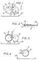
- an abrasive mixture containing abrasive material, temporary binder and ceramic bond is fed to a heated extruder 1 mounted to feed into the nip 2 between intermeshed profiling wheel 3 and supporting wheel 4, the latter being to receive an annular band of the abrasive mixture.
- Supporting wheel 4 comprises a central hub 5 that will form the supporting centre of the eventual product and two side constraint plates 6 coaxially mounted one on each side of hub 5 but being of larger diameter to define an annular gap 7 around the circumference of hub 5 in which the annular abrasive band will be formed.
- Profileing wheel 3 has a shape at its circumference 8 that is the counter profile corresponding to the desired profile of the annular abrasive band.
- the abrasive mixture fed into nip 2 is constrained to form an annular band around hub 5 by clockwise rotation of wheel 4 and anti-clockwise rotation of wheel 3 during the extrusion.
- the size of the nip may be increased during the process to increase the thickness of the applied band. This may be achieved by any suitable mechanism to increase the distance between wheels 3 and 5, either of which may be moveable towards and away from the other.
- Wheel 3 is formed of an anti-stick material or with an anti-stick coating to discourage pick-up of the abrasive mixture.
- it may be of P.T.F.E., polymethyl methacrylate, aluminium or steel.
- a scraper 9 in contact with wheel 3 removes any such mixture that does attach to the wheel and deposits it in recovery tray 10.
- wheel 5 and the band of mixture forming on it may be warmed or cooled as appropriate, e.g. by means of a hot/cold air blower (not shown). Wheel 3 may similarly be warmed or cooled, if desired.
- Figure 3 shows an annular band 11 of the abrasive mixture forming within gap 7 of wheel 4.
- Figure 4 shows hub 5 with the side restraints removed and having annular band 11 around its circumference. While still in the unfired 'green' state, further profiling of the circumference may take place, e.g. by rotation in contact with tool 12.
- the shaped product is then placed in a furnace and fired to a temperature between 500°C and 1400°C to remove the organic binder constituent and fuse the ceramic bond to form the desired product in which the abrasive annular band 11 is firmly bonded to the supporting central hub.
- a controlled firing regime is used to allow the binder to be driven off at a relatively low temperature before final firing at a higher temperature within the range.
- the actual conditions required will, of course, vary from mixture to mixture but will be readily determinable by the average skilled man of the art.
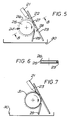
- a similar abrasive mixture is fed to heated extruder 21 mounted to feed into the nip 22 between a forming bar 23 and supporting wheel 24, the latter, as in Figure 1, being to receive an annular band of the abrasive mixture.
- support wheel 24 comprises a central hub 25 that will form the supporting centre of the eventual product and two side constraint plates 26 coaxially mounted one on each side of hub 25 but being of larger diameter to define an annular gap 27 around the circumference of hub 25 in which the annular abrasive band will be formed.
- Forming bar 23 has a profile at its face 28, which contacts the abrasive annular band, that is the counter profile of the desired profile of the band.
- the abrasive mixture fed in to nip 22 is constrained to form an annular band around hub 25 by clockwise rotation of wheel 24 during the extrusion.
- the size of the nip may be increased during the process to increase the thickness of the applied band.
- forming bar 23 may be of or coated with anti-stick material.
- Scraper 29 removes excess mixture and deposits it in recovery tray 30.
- Hub 25 and the band of mixture forming on it may be warmed or cooled as appropriate by means of a hot/cold air blower (again not shown).
- Forming bar 23 may similarly be warmed or cooled, if desired.
- Figure 7 shows an annular band 31 of the abrasive mixture forming within gap 27 of wheel 24.
- band 31 After formation of band 31 is completed, the side restraints are removed as before and the shaped product fired as described above in a furnace to remove the temporary binder and fuse the ceramic bond.
Landscapes
- Engineering & Computer Science (AREA)
- Manufacturing & Machinery (AREA)
- Mechanical Engineering (AREA)
- Polishing Bodies And Polishing Tools (AREA)
Abstract
Description
- This invention relates to grinding tools, particularly to vitrified bonded grinding tools and to a method of making such tools.
- Grinding tools, e.g. wheels, are well known for the working of, for example, metals and ceramics. Such wheels typically comprise a band of suitable grinding material, e.g. of cubic boron nitride or of diamond, aluminium oxide, silicon carbide or mixtures thereof, bonded to the periphery of a supporting disc, which may be of any suitable material, e.g. metal, ceramic or plastics material.
- Various methods for the manufacture of grinding wheels are known. The abrasive medium is usually mixed in a suitable bonding material and cold pressed, hot-pressed or pressure-sintered around the rim of the supporting disc in a suitable mould to form the annular abrasive band around the rim.
- US-A-3794474 describes an alternative technique in which a ceramic profiled supporting grinding wheel is used to grind a counter profile in a steel mould, the diameter of the supporting wheel is reduced so that a gap is formed between it and the profiled steel mould, and a mixture of cold-setting synthetic binder and diamond grains is coated on the circumference of the supporting disc which is then rotated in the mould to shape the grinding band around said periphery.
- US-A-4634453 discloses a method of making a grinding tool using a slurry of abrasive material and a ceramic bond which is applied as a coating on a support member and then fired. The slurry is coated onto the peripheral surface of a porous ceramic hub, while applying vacuum through the hub, conforming the surface of the coating to the desired shape and firing it to produce the desired grinding annulus on the hub.
- This invention aims to provide an improved method of forming the desired abrasive grinding portion on a supporting hub or disc.
- Accordingly, the invention provides a method of making a grinding tool, the method comprising applying a mixture of abrasive material and ceramic bond to form a coating on a portion of the exterior of a supporting member and firing the applied mixture characterised in that the mixture includes a softenable temporary binder and is heated to a paste-like consistency which is coated on to the supporting member and the coated member is fired to drive off the temporary binder and to fuse the ceramic bond whereby the coating is firmly bonded to the support member.
- It is known from US-A-3416905 to incorporate a temporary binder when making ceramic articles by casting or die moulding but there is no disclosure or foreshadowing of the coating of a heated paste.
- The invention will be more specifically described with reference to abrasive grinding wheels in which the supporting member is a disc or wheel and the abrasive mixture is formed as a band around the circumference of the disc, the band being generally annular in shape.
- It will be appreciated that any desired profile may be applied to the band before it is fired into its final form. In particular, the profile of the circumference of the supporting disc onto which the abrasive mixture is formed may be flat and the abrasive mixture may be shaped into any desired profile by means of a suitable forming tool. Alternatively, the profile of the circumference of the supporting disc may have any suitable non-re-entrant shape as may the profiled abrasive band. Thus the band may have a flat profile on a flat supporting profile, a curved, non-re-entrant profile on a flat supporting profile or either a flat or curved, non-re-entrant profile on a curved non-re-entrant profile.
- The temporary binder may be, for example, polyethylene glycol, stearic acid, polyvinyl alcohol or polyacrylic acid.
- The temporary binder has the properties such that when the mixture is heated prior to its application to the supporting member, it melts or softens sufficiently to make the consistency of the mixture paste-like for ease of application. After application of the paste-like mixture, the temporary binder solidifies again as the mixture cools and it then acts as green binder for the formed but unfired product. On firing, the temporary binder is driven off and the coherence of the product is then maintained by the fusion of the ceramic bond constituent.
- The abrasive material is preferably diamond grains or cubic boron nitride grains. They may, for example, have sizes in the range 1 mm to 1 micron or even less.
- Optionally a filler material, e.g. aluminium oxide or silicon carbide, may be included with the abrasive material.
- The ceramic bond may be, for example, a powdered glass frit and/or a powdered mixture of suitable glass-forming materials, e.g. clay, feldspar and borax.
- The proportions of the constituents are preferably as follows, the amounts being by volume:
- abrasive
- 5 to 75%
- filler
- 0 to 75%
- ceramic bond
- 5 to 50%
- temporary binder
- 5 to 50%
- As indicated above, the raw materials to form the abrasive mixture are blendable to form a homogeneous mixture of paste-like consistency and it is preferred that the mixture of abrasive material, temporary binder and ceramic bond be applied to the supporting disc by an extrusion technique.
- The band of abrasive mixture is preferably profiled by feeding the heated mixture into the nip between the supporting disc and a profiling wheel, the latter having the counter profile of the desired product.
- Embodiments of the invention will now be described by way of illustration only by reference to the accompanying drawings in which:-
- Figure 1 is a diagrammatic illustration of an apparatus for applying a heated extruded abrasive mixture to the circumference of a supporting wheel;
- Figure 2 is a section on line A - A of Figure 1;
- Figure 3 is a similar view to that of Figure 1 after the extrusion has been applied;
- Figure 4 is a diagrammatic illustration of the supporting wheel with its applied circumferential band prior to the firing;
- Figure 5 is a diagrammatic illustration of an alternative apparatus for applying a heated extruded abrasive mixture to the circumference of a supporting wheel;
- Figure 6 is a section on line B - B of Figure 5; and
- Figure 7 is a similar view to that of Figure 5 after the extrusion has been applied.
- Referring to Figures 1 and 2, an abrasive mixture containing abrasive material, temporary binder and ceramic bond is fed to a heated extruder 1 mounted to feed into the nip 2 between intermeshed profiling
wheel 3 and supporting wheel 4, the latter being to receive an annular band of the abrasive mixture. - Supporting wheel 4 comprises a
central hub 5 that will form the supporting centre of the eventual product and two side constraint plates 6 coaxially mounted one on each side ofhub 5 but being of larger diameter to define an annular gap 7 around the circumference ofhub 5 in which the annular abrasive band will be formed. Profilingwheel 3 has a shape at its circumference 8 that is the counter profile corresponding to the desired profile of the annular abrasive band. - The abrasive mixture fed into nip 2 is constrained to form an annular band around
hub 5 by clockwise rotation of wheel 4 and anti-clockwise rotation ofwheel 3 during the extrusion. The size of the nip may be increased during the process to increase the thickness of the applied band. This may be achieved by any suitable mechanism to increase the distance betweenwheels -
Wheel 3 is formed of an anti-stick material or with an anti-stick coating to discourage pick-up of the abrasive mixture. For example it may be of P.T.F.E., polymethyl methacrylate, aluminium or steel. Additionally, a scraper 9 in contact withwheel 3 removes any such mixture that does attach to the wheel and deposits it in recovery tray 10. - If desired
wheel 5 and the band of mixture forming on it may be warmed or cooled as appropriate, e.g. by means of a hot/cold air blower (not shown).Wheel 3 may similarly be warmed or cooled, if desired. - Figure 3 shows an annular band 11 of the abrasive mixture forming within gap 7 of wheel 4.
- Figure 4 shows
hub 5 with the side restraints removed and having annular band 11 around its circumference. While still in the unfired 'green' state, further profiling of the circumference may take place, e.g. by rotation in contact withtool 12. - The shaped product is then placed in a furnace and fired to a temperature between 500°C and 1400°C to remove the organic binder constituent and fuse the ceramic bond to form the desired product in which the abrasive annular band 11 is firmly bonded to the supporting central hub.
- A controlled firing regime is used to allow the binder to be driven off at a relatively low temperature before final firing at a higher temperature within the range. The actual conditions required will, of course, vary from mixture to mixture but will be readily determinable by the average skilled man of the art.
- Referring to Figures 5 and 6, a similar abrasive mixture is fed to heated
extruder 21 mounted to feed into thenip 22 between a formingbar 23 and supportingwheel 24, the latter, as in Figure 1, being to receive an annular band of the abrasive mixture. - As in Figure 1,
support wheel 24 comprises acentral hub 25 that will form the supporting centre of the eventual product and twoside constraint plates 26 coaxially mounted one on each side ofhub 25 but being of larger diameter to define anannular gap 27 around the circumference ofhub 25 in which the annular abrasive band will be formed. Formingbar 23 has a profile at itsface 28, which contacts the abrasive annular band, that is the counter profile of the desired profile of the band. - As in the previous embodiment, the abrasive mixture fed in to
nip 22 is constrained to form an annular band aroundhub 25 by clockwise rotation ofwheel 24 during the extrusion. As before, the size of the nip may be increased during the process to increase the thickness of the applied band. - As for
wheel 3 of the previous embodiment, formingbar 23 may be of or coated with anti-stick material.Scraper 29 removes excess mixture and deposits it inrecovery tray 30. -
Hub 25 and the band of mixture forming on it may be warmed or cooled as appropriate by means of a hot/cold air blower (again not shown). Formingbar 23 may similarly be warmed or cooled, if desired. - Figure 7 shows an
annular band 31 of the abrasive mixture forming withingap 27 ofwheel 24. - After formation of
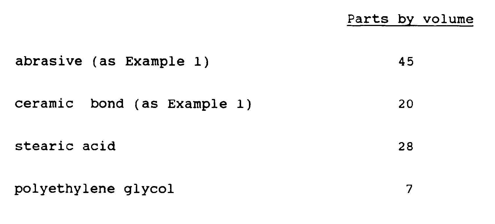
band 31 is completed, the side restraints are removed as before and the shaped product fired as described above in a furnace to remove the temporary binder and fuse the ceramic bond. - Examples of suitable abrasive mixtures are given below.
-

-
Claims (13)
- A method of making a grinding tool, the method comprising applying a mixture of abrasive material and ceramic bond to form a coating (11,31) on a portion of the exterior of a supporting member (4,24) and firing the applied mixture characterised in that the mixture includes a softenable temporary binder and is first heated to a paste-like consistency which is then applied as a coating on to the supporting member (4,24) and the coated member is fired to drive off the temporary binder and to fuse the ceramic bond whereby the coating is firmly bonded to the support member (4,24).
- A method according to Claim 1 characterised in that the heated paste is extruded onto the supporting member (4,24).
- A method according to Claim 1 or 2 characterised in that the softenable temporary binder is polyethylene glycol, stearic acid, polyvinyl alcohol or polyacrylic acid.
- A method according to any preceding Claim characterised in that the heated paste is supplied by a heated extruder.
- A method according to any preceding Claim characterised in that the supporting member is a wheel (5,25) and the heated paste is applied to form an annular band (11, 31) around the circumference of the wheel.
- A method according to Claim 5 characterised in that a pair of side plates (6,26) is attached co-axially to the wheel (5,25), one on each side, the side plates being of larger diameter than the wheel, whereby an annular gap (7,27) to receive the paste is formed about the circumference of the wheel.
- A method according to Claim 6 characterised in that a profiling wheel (3) meshes into the annular gap (7) and a supporting wheel (5) and profiling wheel (3) are rotated in opposite directions as the paste is fed into the nip (2) between the wheels.
- A method according to Claim 7 characterised in that the profile of the circumference (8) of the profiling wheel (3) is flat to impart a flat profile to the formed annular band (11).
- A method according to Claim 7 characterised in that the circumference (8) of the profiling wheel (3) has a curved non-re-entrant profile to impart a curved non-re-entrant profile to the formed annular band (11).
- A method according to any of Claims 1 to 5 characterised in that a forming bar (23) is provided to form a nip (22) in co-operation with the supporting wheel (24,25) and the heated paste is fed into the nip during rotation of the wheel.
- A method according to any one of the preceding Claims, characterised in that the ceramic bond is a powdered glass frit and/or a powdered mixture of clay, feldspar and borax.
- A method according to any one of the preceding Claims, characterised in that the abrasive material comprises diamond or cubic boron nitride.
- A method according to any one of the preceding Claims, characterised in that the coated paste is fired in stages in a range from 500°C to 1400°C.
Applications Claiming Priority (2)
| Application Number | Priority Date | Filing Date | Title |
|---|---|---|---|
| GB8915449 | 1989-07-06 | ||
| GB898915449A GB8915449D0 (en) | 1989-07-06 | 1989-07-06 | Grinding tools |
Publications (3)
| Publication Number | Publication Date |
|---|---|
| EP0407069A2 EP0407069A2 (en) | 1991-01-09 |
| EP0407069A3 EP0407069A3 (en) | 1991-07-17 |
| EP0407069B1 true EP0407069B1 (en) | 1994-07-13 |
Family
ID=10659606
Family Applications (1)
| Application Number | Title | Priority Date | Filing Date |
|---|---|---|---|
| EP90306845A Expired - Lifetime EP0407069B1 (en) | 1989-07-06 | 1990-06-22 | Grinding tools |
Country Status (6)
| Country | Link |
|---|---|
| US (1) | US5094671A (en) |
| EP (1) | EP0407069B1 (en) |
| JP (1) | JPH0349874A (en) |
| AT (1) | ATE108359T1 (en) |
| DE (1) | DE69010587T2 (en) |
| GB (1) | GB8915449D0 (en) |
Families Citing this family (9)
| Publication number | Priority date | Publication date | Assignee | Title |
|---|---|---|---|---|
| DE4032452C1 (en) * | 1990-10-12 | 1992-02-20 | Didier-Werke Ag, 6200 Wiesbaden, De | |
| GB2256434A (en) * | 1991-06-04 | 1992-12-09 | Rolls Royce Plc | Abrasive medium |
| DE4300722A1 (en) * | 1993-01-14 | 1994-07-21 | Mecano Vorrichtungsbau Gmbh | Method of making grinding tools and tool made thereafter |
| ZA9410384B (en) * | 1994-04-08 | 1996-02-01 | Ultimate Abrasive Syst Inc | Method for making powder preform and abrasive articles made therefrom |
| JPH10151548A (en) * | 1996-09-26 | 1998-06-09 | Aisin Seiki Co Ltd | Abrasive holding grinding method |
| RU2149750C1 (en) * | 1999-03-22 | 2000-05-27 | Общество с ограниченной ответственностью "Торговый дом "Абразивные заводы Урала" | Method and device for moulding of abrasive tool blanks |
| IT1307795B1 (en) * | 1999-09-10 | 2001-11-19 | Riccardo Garibaldi | ABRASIVE COMPOSITION FOR THE PRODUCTION OF TOOLS FOR THE IMPLEMENTATION OF SURFACE TREATMENTS IN THE SECTOR OF STONE MATERIALS AND |
| US20030055699A1 (en) * | 2001-09-18 | 2003-03-20 | O'connor Joseph J. | Employee development management method and system |
| WO2015097704A1 (en) * | 2013-12-25 | 2015-07-02 | Camel Grinding Wheels | Abrasive surface preparation |
Family Cites Families (24)
| Publication number | Priority date | Publication date | Assignee | Title |
|---|---|---|---|---|
| US1338598A (en) * | 1916-07-24 | 1920-04-27 | Charles W Thomas | Method of making abrasive structures |
| GB487287A (en) * | 1936-07-22 | 1938-06-17 | Norton Grinding Wheel Co Ltd | Grinding wheel |
| US2544060A (en) * | 1945-10-19 | 1951-03-06 | Exolon Company | Ceramic coatings and method of applying |
| US2837416A (en) * | 1954-10-13 | 1958-06-03 | Norton Co | Vitrified bonded silicon carbide abrasive articles |
| US3249410A (en) * | 1962-09-28 | 1966-05-03 | A P De Sanno & Son Inc | Process of making metal bonded diamond abrasive articles |
| GB1163811A (en) * | 1963-10-07 | 1969-09-10 | Toolmasters Ltd | Method of Forming a Grinding Member |
| US3416905A (en) * | 1965-06-25 | 1968-12-17 | Lexington Lab Inc | Process for manufacture of porous abrasive articles |
| US3528790A (en) * | 1968-02-20 | 1970-09-15 | Norton Co | Resin bonded aluminum oxide abrasive products having improved strength |
| GB1273253A (en) * | 1968-09-25 | 1972-05-03 | Carbond Corp | Improvements in and relating to abrading tools |
| BE756447A (en) * | 1969-10-15 | 1971-03-22 | Pfizer | OXINDOLECARBOXAMIDES |
| BE758965A (en) * | 1969-11-14 | 1971-05-13 | Norton Co | ABRASIVE GRINDING ELEMENTS |
| DE2034521A1 (en) * | 1970-07-11 | 1972-01-20 | Ernst Winter & Sohn, 2000 Hamburg | Binding compsn for grinding tools - contg non-metallic binder, graphite filler and metal filler(s) |
| NL7013165A (en) * | 1970-09-05 | 1972-03-07 | ||
| GB1269589A (en) * | 1970-09-17 | 1972-04-06 | Fernand Leon Gerin | Viscosity gauging device |
| US3864101A (en) * | 1972-04-19 | 1975-02-04 | Sherwin Williams Co | Process for preparing a resin-bonded grinding article containing stress-absorbing particulate material |
| JPS55189B2 (en) * | 1972-07-31 | 1980-01-07 | ||
| US3950149A (en) * | 1974-05-16 | 1976-04-13 | Heijiro Fukuda | Method for continuously producing resinoid wheels |
| DE2657881A1 (en) * | 1976-12-21 | 1978-06-22 | Sia Schweizer Schmirgel & Schl | ABRASIVES |
| JPS5633162U (en) * | 1979-08-22 | 1981-04-01 | ||
| US4334895A (en) * | 1980-05-29 | 1982-06-15 | Norton Company | Glass bonded abrasive tool containing metal clad graphite |
| CS236202B1 (en) * | 1982-08-10 | 1985-05-15 | Josef Kiefman | Compound for grinding tolls making especially for grinding wheels,segments,stones and files |
| DE3346916A1 (en) * | 1983-12-24 | 1985-07-04 | Elbel-Raberain, Anne-Marie, 7530 Pforzheim | METHOD FOR PRODUCING ELASTIC GRINDING BODIES |
| US4634453A (en) * | 1985-05-20 | 1987-01-06 | Norton Company | Ceramic bonded grinding wheel |
| US4867759A (en) * | 1987-12-18 | 1989-09-19 | The Dow Chemical Company | Binder for abrasive greenware |
-
1989
- 1989-07-06 GB GB898915449A patent/GB8915449D0/en active Pending
-
1990
- 1990-06-13 US US07/537,124 patent/US5094671A/en not_active Expired - Fee Related
- 1990-06-22 DE DE69010587T patent/DE69010587T2/en not_active Expired - Fee Related
- 1990-06-22 AT AT90306845T patent/ATE108359T1/en not_active IP Right Cessation
- 1990-06-22 EP EP90306845A patent/EP0407069B1/en not_active Expired - Lifetime
- 1990-07-02 JP JP2175142A patent/JPH0349874A/en active Pending
Also Published As
| Publication number | Publication date |
|---|---|
| EP0407069A2 (en) | 1991-01-09 |
| GB8915449D0 (en) | 1989-08-23 |
| DE69010587D1 (en) | 1994-08-18 |
| JPH0349874A (en) | 1991-03-04 |
| US5094671A (en) | 1992-03-10 |
| EP0407069A3 (en) | 1991-07-17 |
| DE69010587T2 (en) | 1994-10-20 |
| ATE108359T1 (en) | 1994-07-15 |
Similar Documents
| Publication | Publication Date | Title |
|---|---|---|
| EP0577805B1 (en) | Shrinkage reducing composition for bonded abrasive article | |
| JP3336015B2 (en) | Manufacturing method of highly permeable whetstone | |
| EP0357380B1 (en) | Manufacture of abrasive products | |
| JP5162679B2 (en) | Vitrified superabrasive machining tool and manufacturing method | |
| EP3221087B1 (en) | Bonded abrasive articles and methods of manufacture | |
| JP2006520699A (en) | Use of abrasive articles with agglomerates | |
| EP1100654B1 (en) | Vitreous bond compositions for abrasive articles | |
| US5094671A (en) | Grinding tools | |
| EP0892696B1 (en) | Vitreous grinding tool containing metal coated abrasive | |
| CN109848871B (en) | Multi-block diamond grinding tool and manufacturing method thereof | |
| CA2177820C (en) | Method and abrasive article produced thereby | |
| US3717694A (en) | Hot pressing a refractory article of complex shape in a mold of simple shape | |
| EP0321209B1 (en) | Binder for abrasive greenware | |
| US4286981A (en) | Mould with separating layer for the production of glass objects | |
| JP2001088035A (en) | Porous or air hole incorporating type grinding wheel/ stone | |
| US2534127A (en) | Method of manufacturing vitrified grinding wheels | |
| US4554117A (en) | Method of forming dense ceramic bodies | |
| JPH06312376A (en) | Ultra-abrasive wheel embedded therein with striplike chips, for precise cutting | |
| JP3050371B2 (en) | Superabrasive grindstone and method of manufacturing the same | |
| JP3365175B2 (en) | Vitreous Coated Cubic Boron Nitride Abrasives and Method for Producing Vitrified Bond Grinding Stone Using the Same | |
| JPH08276366A (en) | Superabrasive resin bond grindstone and method for manufacturing the same | |
| KR100551216B1 (en) | Diamond Green Tape Manufacturing Method Using Tape Casting Method and Diamond Green Tape | |
| EP0121516B1 (en) | Method of forming dense ceramic bodies | |
| JPH0655457A (en) | Lightweight super abrasive grain metal bond wheel and its manufacture | |
| KR20010081565A (en) | Method of manufacturing grind stone use for a carbide alloy powder |
Legal Events
| Date | Code | Title | Description |
|---|---|---|---|
| PUAI | Public reference made under article 153(3) epc to a published international application that has entered the european phase |
Free format text: ORIGINAL CODE: 0009012 |
|
| AK | Designated contracting states |
Kind code of ref document: A2 Designated state(s): AT BE CH DE DK ES FR GB GR IT LI LU NL SE |
|
| PUAL | Search report despatched |
Free format text: ORIGINAL CODE: 0009013 |
|
| AK | Designated contracting states |
Kind code of ref document: A3 Designated state(s): AT BE CH DE DK ES FR GB GR IT LI LU NL SE |
|
| 17P | Request for examination filed |
Effective date: 19911011 |
|
| 17Q | First examination report despatched |
Effective date: 19930128 |
|
| GRAA | (expected) grant |
Free format text: ORIGINAL CODE: 0009210 |
|
| RAP1 | Party data changed (applicant data changed or rights of an application transferred) |
Owner name: UNICORN ABRASIVES LIMITED |
|
| AK | Designated contracting states |
Kind code of ref document: B1 Designated state(s): AT BE CH DE DK ES FR GB GR IT LI LU NL SE |
|
| PG25 | Lapsed in a contracting state [announced via postgrant information from national office to epo] |
Ref country code: NL Effective date: 19940713 Ref country code: LI Effective date: 19940713 Ref country code: GR Free format text: LAPSE BECAUSE OF FAILURE TO SUBMIT A TRANSLATION OF THE DESCRIPTION OR TO PAY THE FEE WITHIN THE PRESCRIBED TIME-LIMIT Effective date: 19940713 Ref country code: ES Free format text: THE PATENT HAS BEEN ANNULLED BY A DECISION OF A NATIONAL AUTHORITY Effective date: 19940713 Ref country code: DK Effective date: 19940713 Ref country code: CH Effective date: 19940713 Ref country code: BE Effective date: 19940713 Ref country code: AT Effective date: 19940713 |
|
| REF | Corresponds to: |
Ref document number: 108359 Country of ref document: AT Date of ref document: 19940715 Kind code of ref document: T |
|
| REF | Corresponds to: |
Ref document number: 69010587 Country of ref document: DE Date of ref document: 19940818 |
|
| ET | Fr: translation filed | ||
| ITF | It: translation for a ep patent filed | ||
| REG | Reference to a national code |
Ref country code: CH Ref legal event code: PL |
|
| NLV1 | Nl: lapsed or annulled due to failure to fulfill the requirements of art. 29p and 29m of the patents act | ||
| EAL | Se: european patent in force in sweden |
Ref document number: 90306845.0 |
|
| PLBE | No opposition filed within time limit |
Free format text: ORIGINAL CODE: 0009261 |
|
| STAA | Information on the status of an ep patent application or granted ep patent |
Free format text: STATUS: NO OPPOSITION FILED WITHIN TIME LIMIT |
|
| PG25 | Lapsed in a contracting state [announced via postgrant information from national office to epo] |
Ref country code: SE Effective date: 19950623 |
|
| PG25 | Lapsed in a contracting state [announced via postgrant information from national office to epo] |
Ref country code: LU Free format text: LAPSE BECAUSE OF NON-PAYMENT OF DUE FEES Effective date: 19950630 |
|
| 26N | No opposition filed | ||
| PG25 | Lapsed in a contracting state [announced via postgrant information from national office to epo] |
Ref country code: FR Effective date: 19960229 |
|
| EUG | Se: european patent has lapsed |
Ref document number: 90306845.0 |
|
| REG | Reference to a national code |
Ref country code: FR Ref legal event code: ST |
|
| PGFP | Annual fee paid to national office [announced via postgrant information from national office to epo] |
Ref country code: GB Payment date: 20010619 Year of fee payment: 12 |
|
| PGFP | Annual fee paid to national office [announced via postgrant information from national office to epo] |
Ref country code: DE Payment date: 20010827 Year of fee payment: 12 |
|
| REG | Reference to a national code |
Ref country code: GB Ref legal event code: IF02 |
|
| PG25 | Lapsed in a contracting state [announced via postgrant information from national office to epo] |
Ref country code: GB Free format text: LAPSE BECAUSE OF NON-PAYMENT OF DUE FEES Effective date: 20020622 |
|
| PG25 | Lapsed in a contracting state [announced via postgrant information from national office to epo] |
Ref country code: DE Free format text: LAPSE BECAUSE OF NON-PAYMENT OF DUE FEES Effective date: 20030101 |
|
| GBPC | Gb: european patent ceased through non-payment of renewal fee |
Effective date: 20020622 |
|
| PG25 | Lapsed in a contracting state [announced via postgrant information from national office to epo] |
Ref country code: IT Free format text: LAPSE BECAUSE OF NON-PAYMENT OF DUE FEES;WARNING: LAPSES OF ITALIAN PATENTS WITH EFFECTIVE DATE BEFORE 2007 MAY HAVE OCCURRED AT ANY TIME BEFORE 2007. THE CORRECT EFFECTIVE DATE MAY BE DIFFERENT FROM THE ONE RECORDED. Effective date: 20050622 |