EP0406858A2 - A battery charger and method for a portable wireless telephone set having means for tricklingly charging the battery with an increased current during a stand-by period of the telephone set - Google Patents
A battery charger and method for a portable wireless telephone set having means for tricklingly charging the battery with an increased current during a stand-by period of the telephone set Download PDFInfo
- Publication number
- EP0406858A2 EP0406858A2 EP90112852A EP90112852A EP0406858A2 EP 0406858 A2 EP0406858 A2 EP 0406858A2 EP 90112852 A EP90112852 A EP 90112852A EP 90112852 A EP90112852 A EP 90112852A EP 0406858 A2 EP0406858 A2 EP 0406858A2
- Authority
- EP
- European Patent Office
- Prior art keywords
- battery
- charging
- current
- signal
- control signal
- Prior art date
- Legal status (The legal status is an assumption and is not a legal conclusion. Google has not performed a legal analysis and makes no representation as to the accuracy of the status listed.)
- Granted
Links
Images


Classifications
-
- H—ELECTRICITY
- H02—GENERATION; CONVERSION OR DISTRIBUTION OF ELECTRIC POWER
- H02J—CIRCUIT ARRANGEMENTS OR SYSTEMS FOR SUPPLYING OR DISTRIBUTING ELECTRIC POWER; SYSTEMS FOR STORING ELECTRIC ENERGY
- H02J7/00—Circuit arrangements for charging or depolarising batteries or for supplying loads from batteries
- H02J7/007—Regulation of charging or discharging current or voltage
- H02J7/00712—Regulation of charging or discharging current or voltage the cycle being controlled or terminated in response to electric parameters
- H02J7/007182—Regulation of charging or discharging current or voltage the cycle being controlled or terminated in response to electric parameters in response to battery voltage
-
- H—ELECTRICITY
- H02—GENERATION; CONVERSION OR DISTRIBUTION OF ELECTRIC POWER
- H02J—CIRCUIT ARRANGEMENTS OR SYSTEMS FOR SUPPLYING OR DISTRIBUTING ELECTRIC POWER; SYSTEMS FOR STORING ELECTRIC ENERGY
- H02J7/00—Circuit arrangements for charging or depolarising batteries or for supplying loads from batteries
- H02J7/34—Parallel operation in networks using both storage and other dc sources, e.g. providing buffering
- H02J7/342—The other DC source being a battery actively interacting with the first one, i.e. battery to battery charging
Abstract
Description
- The present invention relates to a battery charger for a portable wireless telephone set and, in particular, to such a battery charger having a function for tricklingly charging the battery after the battery is charged to its normal voltage.
- A portable wireless telephone set has a battery with a normal voltage as a power source for a transmitter and a receiver of the telephone set. The battery energy is consumed when the telephone set is used for telephone communication. Therefore, it is necessary that the battery is charged when the telephone set is not used for the telephone communication.
- To this end, a battery charger is usually provided for the portable wireless telephone set so as to charge the battery.
- A known battery charger for use in a portable wireless telephone set comprises a rapidly charging circuit and a tricklingly charging circuit which are selectively operated under control of a charge controller.
- At a start of the battery charge, the rapidly charging circuit generates a high level DC current for rapidly charging the battery. Once the battery is charged to the normal voltage, the rapidly charging circuit is stopped by the charge controller and the trickling charging circuit then generates a considerably low level current for tricklingly charging the battery.
- The battery charger has a charge detecting circuit for detecting whether or not the battery is charged to the normal voltage. When the charge detecting circuit detects that the battery is charged to the normal voltage, the charge detecting circuit produces a detected signal which is delivered to the charge controller. Then, the charge controller stops the rapidly charging circuit and makes the tricklingly charging circuit operate to produce the low level DC current. Accordingly, the battery is tricklingly charged by the low level DC current.
- When the battery is being charged, it is provided that a power switch of the telephone set should be turned off. Therefore, the trickling charging circuit is designed to produce such a low level DC current that the battery is not excessively charged.
- On the other hand, when the power switch is turned on for a stand-by or a call waiting condition, the battery energy is also consumed but at a rate lower than a condition for the telephone communication. Therefore, when the power switch of the telephone set is left in an on condition, the battery is charged to the normal voltage by the rapidly charging circuit of the battery charger but the battery energy is consumed after the battery charging operation is turned from the rapidly charging circuit to the trickling charging circuit, so that the battery is insufficiently charged. This results into a fact that the next telephone communication is impossible or limited to a reduced communication time duration by use of the telephone set.
- Accordingly, it is an object of the present invention to provide a battery charger for a portable wireless telephone set having a battery with a normal voltage which enables to maintain the normal voltage of the battery without any excessive charge after rapidly charging the battery to the normal voltage even when a power switch of the telephone set is left in an on condition.
- According to the present invention, a battery charger for a portable wireless telephone set having a battery with a normal voltage as an electric power source for the telephone set is obtained which comprises an output port to be connected to the battery for delivering a charging current to the battery; DC power source for generating a DC power; first charging means coupled to the DC power source and the output port responsive to a first control signal for generating from the DC power a first DC current with a first level sufficient to rapidly charge the battery, the first DC current being delivered to the output port as the charging current; second charging means coupled to the DC power source and the output port responsive to a second control signal for generating from the DC power a second DC current with a second level considerably lower than the first DC current to tricklingly charge the output port as the charging current; third charging means coupled to the DC power source and the output port responsive to a third control signal for generating from the DC power a third DC current with a third level lower than the first DC current but relatively higher than the second DC current, the third DC current being delivered to the output port as the charging current; charge detecting means coupled to the output port for detecting a voltage charged in the battery connected to the output port to produce, as a fourth control signal, a detected signal when the charged voltage reaches the normal battery voltage; and charge controlling means coupled to the charge detecting means for generating the first control signal when the fourth control signal is absent from the charge detecting means, the charge controlling means generating the third control signal in place of the first control signal in response to the fourth control signal when receiving a fifth control signal, the charge controlling means generating the second control signal in place of the first control signal in response to the fourth control signal when receiving none of the fifth control signal.
- In an aspect of the present invention, the portable wireless telephone set has means for generating a power-on signal when the telephone set is powered on. The battery charger further comprises an input terminal to be coupled with the power-on signal generating means, the input terminal connected to the charge controlling means for delivering the power-on signal to the charge controlling means as the fifth control signal.
- When the battery has a capacity C, the second level of the second DC current is determined to be a value of C/25 to C/15.
- The battery supplies a stand-by current during a stand-by condition of the telephone set when the telephone set is powered on. Then, the third level of the third DC current is determined to be a sum of the value of the second level and a level of the stand-by current.
- The invention will be described in detail in connection with the drawings in which
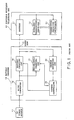
- Fig. 1 is a view illustrating a block diagram of a known battery charger together with a portable wireless telephone set;
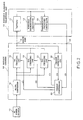
- Fig. 2 is a view illustrating a block diagram of a battery charger according to an embodiment of the present invention together with a portable wireless telephone set;
- Fig. 3 is a flow chart illustrating operation of a charge controller in Fig. 2;
- Fig. 4 is a circuit diagram view of a charging circuit used for the first through third charging circuits in Fig. 2; and
- Fig. 5 is a circuit diagram view of a charge detecting circuit in Fig. 2.
- Prior to description of embodiments of the present invention, a known battery charger for a portable wireless telephone set will be described so as to help the better understanding of the present invention.
- Referring to Fig. 1, a portable
wireless telephone set 10 comprises a battery or a chargeableelectric cell 11 such as a Ni-Cd cell, a wireless transmitter/receiver 12 and a transmitter/receiver controller 13. Thebattery 11 is a power source for the transmitter/receiver 12 and the transmitter/receiver controller 13 and has a normal voltage sufficient to drive them. - In order to charge the
battery 11 so as to compensate consumption of the battery energy, thetelephone set 10 is provided with abattery charger 14 which is connectable to thetelephone set 10. - The
battery charger 14 comprises anoutput port 15 to be connected to thebattery 11 for delivering a charging current to thebattery 11, and a DC power source for providing the charging current. - In the shown embodiment, the DC power source is an AC/
DC converter 16 which is connected to anAC power source 17. The AC/DC converter 16 converts an AC power from theAC power source 17 to a DC power with a DC voltage as a converted DC power. - The
battery charger 14 further comprises a rapidly chargingcircuit 18, a tricklinglycharging circuit 19, charge detectingcircuit 20, and acharge controller 21. - The rapidly charging
circuit 18 is connected to the AC/DC converter 16 and theoutput port 15 and produces a first DC current from the converted DC power when receiving a first control signal from thecharge controller 21. The first DC current is delivered to theoutput port 15 as the charging current and has a first DC level which is sufficient to rapidly charge thebattery 11. - The tricklingly
charging circuit 19 is also connected to the AC/DC converter 16 and theoutput port 15 and produces a second DC current from the converted DC power when receiving a second control signal from thecharge controller 21. The second DC current is delivered to theoutput port 15 as the charging current and has a second DC level which is considerably low to tricklingly charge thebattery 11 after thebattery 11 is charged to the normal voltage. - The
charge detecting circuit 20 is connected to theoutput port 15 and detects a charged voltage of thebattery 11 connected to theoutput port 15. When thecharge detecting circuit 20 detects that thebattery 11 is charged to the normal voltage, thecharge detecting circuit 20 produces a detected signal. - The
charge controller 21 is coupled to thecharge detecting circuit 20 and produces the first control signal when thecharge detecting circuit 20 does not produce the detected signal. Therefore, thebattery 11 is supplied with the first DC current as the charging current and is rapidly charged to the normal voltage. - When the
charge detecting circuit 20 produces the detected signal, thecharge controller 21 receives the detected signal and stops the first control signal but produces the second control signal. Accordingly, the rapidly chargingcircuit 18 is stopped but the tricklinglycharging circuit 19 is driven in response to the second control signal. Thus, thebattery 11 is supplied with the second DC current as the charging current through theoutput port 15 and is tricklingly charged. - The tricklingly
charging circuit 19 is usually designed that the second DC current has a current level of a value determined by C/15 through C/25, where C is a capacity of thebattery 11. When C=1000 mAh, the second DC current is 50 mA. - When a power switch (not shown) of the
telephone set 10 is turned on and the portablewireless telephone set 10 is in a stand-by or a waiting condition for a telephone call, the battery energy is also consumed. In known portable wireless telephone sets, thebattery 11 usually supplies a stand-by current of about 50-100 mA to the wireless transmitter/receiver 12 and the transmitter/receiver controller 13. - Therefore, when the power switch is left on, the
battery 11 is insufficiently charged as described in the preamble of the present description. - Referring to Fig. 2, an embodiment of the present invention shown therein is similar to the known one shown in Fig. 1 except several differences. The similar parts are represented by the same reference numerals as in Fig. 1.
- In the portable
wireless telephone set 10, a transmitter/receiver controller 22 is different from the transmitter/receiver controller 13 in Fig. 1 in a fact that the transmitter/receiver 22 produces a power-on signal c5 when the power switch of thetelephone set 10 is left on. The power-on signal is supplied to thebattery charger 14. - The
battery charger 14 comprises anoutput port 15, an AC/DC converter 16 connected to anAC power source 17, and acharge detecting circuit 20 which are similar to those shown at the same reference numerals in Fig. 1. - The
battery charger 14 further comprises afirst charging circuit 18, asecond charging circuit 19, athird charging circuit 23, and acharge controller 24. The first charging circuit is corresponding to the rapidly chargingcircuit 18 in Fig. 1 and is represented by thesame reference numeral 18. Thesecond charging circuit 19 is also corresponding to the tricklinglycharging circuit 19 in Fig. 1 and is, therefore, represented by thesame reference numeral 19. - The
third charging circuit 23 is coupled to the AC/DC converter 16 and theoutput port 15 and generates a third DC current from the converted DC power from the AC/DC converter 16 when receiving a third control signal. Thethird charging circuit 23 is designed that the third DC current has a level lower than the first DC current but relatively higher than the second DC current. The third.DC current is also supplied to thebattery 11 as the charging current through theoutput port 15. - When the second DC current is determined at C/20, for example, 50 mA for C=1,000 mAh, the third DC current is determined (C/20 + α), for example, (50+70) mA for C=1,000 mAh, where α represents the stand-by current which is consumed by the telephone set in the stand-by condition and is exemplarily 70 mA.
- The
battery charger 14 further comprises aninput terminal 25 to be connected to the transmitter/receiver controller 22 for receiving the power-on signal. - The
charge controller 24 is coupled to thecharge detecting circuit 20 and theinput terminal 25 and controls the first, the second and thethird charging circuits - The
charge controller 24 selectively produces the first, the second, and the third control signals c1, c2, and c3 in dependent on presence and absence of the detected signal as a fourth control signal c4 from thecharge detecting circuit 20 and the power-on signal as a fifth control signal c5 through theinput terminal 25. - Referring to Fig. 3, the
charge controller 24 produces the first control signal c1 of a high level signal and sets the second and the third control signals c2 and c3 at a low level at a start of charging operation, as shown at a step S1. Therefore, thefirst charging circuit 18 produces the first DC current and thebattery 11 is rapidly charged by the first DC current. - Thereafter, when the
charge detecting circuit 20 detects that thebattery 11 is charged to its normal voltage, thecharge detecting circuit 20 detects the detected signal as the fourth control signal c4 of a high level signal. When thecharge controller 24 receives the fourth control signal c4 as shown at a step S2, thecharge controller 24 changes the first control signal c1 to a low level signal and produces the second control signal c2 of a high level at a step of S4 when the fifth control signal c5 of a high level is not supplied to thecharge controller 24 as shown at a step S3. Thus, thesecond charging circuit 19 operates and thebattery 11 is tricklingly charged. - While, when the control signal cS of a high level is supplied to the
charge controller 24 at the step S3, thecharge controller 24 changes the first control signal c1 to a low level signal and produces the third control c3 signal of a high level at a step S5. Therefore, thethird charging circuit 23 operates to produce the third DC current. Thus, the battery is sufficiently charged when the power switch of the telephone set 10 is turned on. - Now, referring to Fig. 4, an example of a circuit is described which is used for each of the first, the second, and
third charging circuits - The circuit shown therein comprises a
PNP transistor 26. An emitter of thetransistor 26 is connected to aninput terminal 27 through aresistor 28 of a resistance of R1. A collector of thetransistor 26 is connected to anoutput terminal 29. A base of thetransistor 26 is connected to acontrol terminal 30 through abase resistor 31 of a resistance of R2 and aninverter circuit 32. AZener diode 33 is connected between the base and the emitter. When a DC power is supplied to theinput terminal 27 and a high level signal is applied to thecontrol terminal 30, the circuit produces a constant DC current at theoutput terminal 29. A value or level of the constant DC current is adjusted by selecting the resistance R1 of theresistor 28. When the resistance R1 is selected small, the constant DC current has a high level. On the other hand, when the resistance R1 is selected large, the constant DC current has a low level. - When a low level signal is applied to the
control terminal 30, the circuit is stopped to produce the DC current. - Therefore, the circuit of Fig. 4 can be used for each of the first, the second, and the
third charging circuits resistor 28. - Referring to Fig. 5, an example of the
charge detecting circuit 20 will now be described. The circuit shown therein comprises aninput terminal 34 which is to be connected to theoutput port 15 in Fig. 2, a voltage divider ofresistors comparator 37 having an inverting input terminal (-), a non-inverting input terminal (+), and anoutput terminal 38. The inverting input terminal (-) is connected to a common connecting point of theresistors diode 39. The non-inverting input terminal (+) is grounded through acapacitor 40. Therefore, the divided voltage is applied across a series circuit of thediode 39 and thecapacitor 40. - During the charging operation for the
battery 11 in Fig. 2, the peak charged voltage of thebattery 11 is divided by the voltage divider (35-36) and then held at thecapacitor 40 through the diode. The held voltage is applied to the non-inverting input terminal (+) of thecomparator 37 as a reference voltage level. Just after thebattery 11 is fully charged, the charged voltage drops by some extent. As a result, the divided voltage at the inverting input terminal (-) falls below the reference voltage at the non-inverting input terminal (+), so that a high level signal is produced at theoutput terminal 38 as the detected signal. Thus, the detected signal indicates that thebattery 11 is fully charged. The detected signal is applied to thecharge controller 24 as the fourth control signal c4.
Claims (12)
an output port to be connected to said battery for delivering a charging current to said battery;
DC power source for generating a DC power;
first charging means coupled to said DC power source and said output port responsive to a first control signal for generating from said DC power a first DC current with a first level sufficient to rapidly charge said battery, said first DC current being delivered to said output port as said charging current;
second charging means coupled to said DC power source and said output port responsive to a second control signal for generating from said DC power a second DC current with a second level considerably lower than said first DC current to tricklingly charge said battery, said second DC current being delivered to said output port as said charging current;
third charging means coupled to said DC power source and said output port responsive to a third control signal for generating from said DC power a third DC current with a third level lower than said first DC current but relatively higher than said second DC current, said third DC current being delivered to, said output port as said charging current;
charge detecting means coupled to said output port for detecting a voltage charged in said battery connected to said output port to produce, as a fourth control signal, a detected signal when said charged voltage reaches said normal battery voltage; and
charge controlling means coupled to said charge detecting means for generating said first control signal when said fourth control signal is absent from said charge detecting means, said charge controlling means generating said third control signal in place of said first control signal in response to said fourth control signal when receiving a fifth control signal, said charge controlling means generating said second control signal in place of said first control signal in response to said fourth control signal when receiving none of said fifth control signal.
first charging means for charging a battery at a first charging current, said battery supplying power to a communication device;
second charging means for charging said battery at a second charging current lower than said first charging current;
third charging means for charging said battery at a third charging current lower than said second charging current;
first detecting means for detecting the fully charged condition of said battery to produce a full charge detect signal;
second detecting means for detecting the ON/OFF condition of said communication device to produce an on-state signal when said device is turned on and an off-state signal when said device is turned off; and
control means for making said first charging means operative in the absence of said full charge detect signal, for making said first and second charging means inoperative and said third charging means operative in the presence of said full charge detect signal and of said off-state signal, and for making said first and third charging means inoperative and said second charging means operative in the presence of said full charge detect signal and of said on-state signal.
a first resistor whose one end is coupled to said AC/DC converter means;
a PNP transistor whose emitter and collector are connected to the other end of said first resistor and said battery, respectively;
a Zener diode whose anode and cathode are connected to the base of said transistor and said one end of said first resistor, respectively;
a second resistor whose one end is connected to said base; and
an inverter whose output and input terminals are connected to the other end of said second resistor and said control means, respectively.
first and second resistors connected in series between said battery and ground;
a comparator whose inverting input and output terminals are connected to the junction of said first and second resistors and said control means, respectively;
a diode whose anode and cathode are connected to the inverting and non-inverting input terminals of said comparator, respectively; and
a capacitor connected between said non-inverting input terminal and ground.
detecting the fully charged condition of said battery to produce a full charge detect signal;
detecting the ON/OFF state of said communication device to produce an on-state signal when said device is in an on-state and an off-state signal when said device is in an off-state;
charging said battery at a first charging current in the absence of said full charge detect signal;
charging said battery at a second charging current in the presence of said full charge detect and on-state signals, said second charging current being lower than said first charging current; and
charging said battery at a third charging current in the presence of said full charge detect and off-state signals, said third charging current being lower than said second charging current.
Applications Claiming Priority (2)
| Application Number | Priority Date | Filing Date | Title |
|---|---|---|---|
| JP171988/89 | 1989-07-05 | ||
| JP1171988A JPH0340728A (en) | 1989-07-05 | 1989-07-05 | Portable radio telephone charger |
Publications (3)
| Publication Number | Publication Date |
|---|---|
| EP0406858A2 true EP0406858A2 (en) | 1991-01-09 |
| EP0406858A3 EP0406858A3 (en) | 1992-03-11 |
| EP0406858B1 EP0406858B1 (en) | 1995-12-20 |
Family
ID=15933452
Family Applications (1)
| Application Number | Title | Priority Date | Filing Date |
|---|---|---|---|
| EP90112852A Expired - Lifetime EP0406858B1 (en) | 1989-07-05 | 1990-07-05 | A battery charger and method for a portable wireless telephone set having means for tricklingly charging the battery with an increased current during a stand-by period of the telephone set |
Country Status (7)
| Country | Link |
|---|---|
| US (1) | US5130634A (en) |
| EP (1) | EP0406858B1 (en) |
| JP (1) | JPH0340728A (en) |
| AU (1) | AU634558B2 (en) |
| CA (1) | CA2020384C (en) |
| DE (1) | DE69024269T2 (en) |
| HK (1) | HK85097A (en) |
Cited By (9)
| Publication number | Priority date | Publication date | Assignee | Title |
|---|---|---|---|---|
| EP0439116A2 (en) * | 1990-01-23 | 1991-07-31 | NEC Corporation | Charge device capable of lengthening a lifetime of a storage cell |
| EP0495728A1 (en) * | 1991-01-18 | 1992-07-22 | Sony Corporation | Battery charger |
| GB2262401A (en) * | 1991-12-09 | 1993-06-16 | Matsushita Electric Ind Co Ltd | Vehicle-mounted charging apparatus for a portable telephone set |
| GB2262668A (en) * | 1991-12-16 | 1993-06-23 | Nec Corp | Battery charging device for a portable telephone |
| GB2242793B (en) * | 1990-04-05 | 1994-08-10 | Technophone Ltd | Battery charging apparatus |
| EP0621649A1 (en) * | 1992-10-13 | 1994-10-26 | Sony Corporation | Battery pack |
| EP0712543A1 (en) * | 1993-08-02 | 1996-05-22 | Motorola, Inc. | Method and apparatus for dynamically charging a battery |
| GB2347565A (en) * | 1999-02-24 | 2000-09-06 | Nec Corp | Charging of mobile phone battery based on state of backlight function |
| CN108899981A (en) * | 2018-08-01 | 2018-11-27 | 广州番禺巨大汽车音响设备有限公司 | A kind of high efficiency storage battery power supply method and device of large size sound equipment |
Families Citing this family (32)
| Publication number | Priority date | Publication date | Assignee | Title |
|---|---|---|---|---|
| KR930011132B1 (en) * | 1991-11-01 | 1993-11-24 | 삼성전자 주식회사 | Control circuit of battery |
| JPH05137271A (en) * | 1991-11-08 | 1993-06-01 | Nec Corp | Charging method of battery |
| US5300875A (en) * | 1992-06-08 | 1994-04-05 | Micron Technology, Inc. | Passive (non-contact) recharging of secondary battery cell(s) powering RFID transponder tags |
| CA2098468C (en) * | 1992-07-07 | 1998-09-01 | David J. Theobald | Method for battery charging |
| US5325040A (en) * | 1992-09-21 | 1994-06-28 | Motorola, Inc. | Method and apparatus for charging a battery powered electronic device |
| KR960016372B1 (en) * | 1992-11-27 | 1996-12-09 | 삼성전자 주식회사 | Charging apparatus and the method having battery activating function |
| EP0623985B1 (en) * | 1993-05-05 | 1998-07-29 | Sgs-Thomson Microelectronics Pte Ltd. | Power Sharing detector |
| US5495519A (en) * | 1993-10-04 | 1996-02-27 | E Lead Electronic Co., Ltd. | Control circuit for control of peripheral equipment of wireless communication appliance |
| US5481174A (en) * | 1993-12-27 | 1996-01-02 | Motorola, Inc. | Method of rapidly charging a lithium ion cell |
| US5587645A (en) * | 1994-03-09 | 1996-12-24 | Sony Corporation | Battery charger with night light for a cordless telephone |
| US5631503A (en) * | 1994-09-16 | 1997-05-20 | Wireless Access Inc. | Apparatus for generating power for use in a communications device |
| JPH0937478A (en) * | 1995-07-21 | 1997-02-07 | Hitachi Koki Co Ltd | Charger |
| JP3228097B2 (en) * | 1995-10-19 | 2001-11-12 | 株式会社日立製作所 | Charging system and electric vehicle |
| JP2914259B2 (en) * | 1995-12-14 | 1999-06-28 | 日本電気株式会社 | Portable electronic device and charge control method for portable electronic device |
| US5764035A (en) * | 1996-09-23 | 1998-06-09 | Ericsson Inc. | System and method for automatically enabling rapid charging of a battery in a portable phone |
| US5821730A (en) * | 1997-08-18 | 1998-10-13 | International Components Corp. | Low cost battery sensing technique |
| JP3882319B2 (en) * | 1998-03-10 | 2007-02-14 | ソニー株式会社 | Power supply adapter, electronic device and signal transmission system |
| US6034504A (en) * | 1998-06-10 | 2000-03-07 | Ericsson Inc. | Two-wire multi-rate battery charger |
| US6040683A (en) * | 1999-05-28 | 2000-03-21 | Motorola, Inc. | Battery charger with active feedback voltage controller |
| JP3714882B2 (en) * | 2001-03-16 | 2005-11-09 | シャープ株式会社 | Portable communication terminal charging system |
| JP4878937B2 (en) * | 2006-06-28 | 2012-02-15 | ソニー・エリクソン・モバイルコミュニケーションズ株式会社 | Mobile device |
| JP5045755B2 (en) | 2007-08-30 | 2012-10-10 | 富士通株式会社 | LIGHTING STRUCTURE FOR KEY OPERATION UNIT, ELECTRONIC DEVICE, PORTABLE DEVICE, AND LIGHTING METHOD FOR KEY OPERATION UNIT |
| US7960944B2 (en) * | 2007-09-05 | 2011-06-14 | Eveready Battery Company, Inc. | Power supply that supplies power to and communicates with an electrical appliance |
| US7825615B2 (en) | 2007-10-16 | 2010-11-02 | Glj, Llc | Intelligent motorized appliances with multiple power sources |
| JP5529652B2 (en) * | 2009-08-27 | 2014-06-25 | セイコーインスツル株式会社 | Charge / discharge control circuit and rechargeable power supply device |
| KR102158288B1 (en) * | 2012-07-09 | 2020-09-21 | 삼성전자주식회사 | Method for charging battery and an electronic device thereof |
| JP6201775B2 (en) * | 2014-01-16 | 2017-09-27 | 富士通株式会社 | Information processing apparatus, power supply control circuit, and AC adapter |
| US10396568B2 (en) | 2014-06-03 | 2019-08-27 | Traxxas Lp | Battery charger with user interface |
| CN206585005U (en) | 2014-06-03 | 2017-10-24 | 特拉克赛卡斯公司 | Battery, rechargeable battery, electrical equipment, electric connector, female electric connector and male electrical connector |
| US10431992B2 (en) * | 2014-06-03 | 2019-10-01 | Traxxas Lp | Battery charger with user interface |
| EP3804078A4 (en) | 2018-05-30 | 2022-02-23 | Milwaukee Electric Tool Corporation | Fast-charging battery pack |
| CN114844135A (en) * | 2021-02-02 | 2022-08-02 | 北京小米移动软件有限公司 | Charging method, charging device, terminal and storage medium |
Citations (4)
| Publication number | Priority date | Publication date | Assignee | Title |
|---|---|---|---|---|
| WO1984000614A1 (en) * | 1982-07-23 | 1984-02-16 | Stubbe Paul K Electronic | Method and device for monitoring the each time-charged capacity of accumulators |
| WO1987007106A1 (en) * | 1986-05-12 | 1987-11-19 | Clinicom Incorporated | Portable handheld terminal including optical bar code reader and electromagnetic transceiver means for interactive wireless communication with a base communications station |
| DE3620857A1 (en) * | 1986-06-21 | 1987-12-23 | Bosch Gmbh Robert | Cordless telephone |
| EP0303067A2 (en) * | 1987-07-16 | 1989-02-15 | Nec Corporation | Cordless telephone with battery saving function |
Family Cites Families (5)
| Publication number | Priority date | Publication date | Assignee | Title |
|---|---|---|---|---|
| US3602794A (en) * | 1970-06-25 | 1971-08-31 | Lawrence A Westhaver | Solid state charging circuitry using a loading coil |
| US3854082A (en) * | 1973-06-07 | 1974-12-10 | Master Control Syst Inc | Battery charging circuit |
| SE427976B (en) * | 1982-09-08 | 1983-05-24 | Tonima Laddelektronik | BATTERY CHARGER WITH POWER CONNECTIONS FOR AC POWER SUPPLY |
| US4670703A (en) * | 1985-05-06 | 1987-06-02 | General Electric Company | Battery charger with three different charging rates |
| JPH02307336A (en) * | 1989-05-19 | 1990-12-20 | Matsushita Electric Ind Co Ltd | Battery charger |
-
1989
- 1989-07-05 JP JP1171988A patent/JPH0340728A/en active Pending
-
1990
- 1990-07-04 CA CA002020384A patent/CA2020384C/en not_active Expired - Fee Related
- 1990-07-05 DE DE69024269T patent/DE69024269T2/en not_active Expired - Fee Related
- 1990-07-05 US US07/548,538 patent/US5130634A/en not_active Expired - Fee Related
- 1990-07-05 EP EP90112852A patent/EP0406858B1/en not_active Expired - Lifetime
- 1990-07-05 AU AU58739/90A patent/AU634558B2/en not_active Ceased
-
1997
- 1997-06-19 HK HK85097A patent/HK85097A/en not_active IP Right Cessation
Patent Citations (4)
| Publication number | Priority date | Publication date | Assignee | Title |
|---|---|---|---|---|
| WO1984000614A1 (en) * | 1982-07-23 | 1984-02-16 | Stubbe Paul K Electronic | Method and device for monitoring the each time-charged capacity of accumulators |
| WO1987007106A1 (en) * | 1986-05-12 | 1987-11-19 | Clinicom Incorporated | Portable handheld terminal including optical bar code reader and electromagnetic transceiver means for interactive wireless communication with a base communications station |
| DE3620857A1 (en) * | 1986-06-21 | 1987-12-23 | Bosch Gmbh Robert | Cordless telephone |
| EP0303067A2 (en) * | 1987-07-16 | 1989-02-15 | Nec Corporation | Cordless telephone with battery saving function |
Cited By (20)
| Publication number | Priority date | Publication date | Assignee | Title |
|---|---|---|---|---|
| EP0439116A3 (en) * | 1990-01-23 | 1993-04-07 | Nec Corporation | Charge device capable of lengthening a lifetime of a storage cell |
| EP0439116A2 (en) * | 1990-01-23 | 1991-07-31 | NEC Corporation | Charge device capable of lengthening a lifetime of a storage cell |
| GB2242793B (en) * | 1990-04-05 | 1994-08-10 | Technophone Ltd | Battery charging apparatus |
| EP0495728A1 (en) * | 1991-01-18 | 1992-07-22 | Sony Corporation | Battery charger |
| US5274321A (en) * | 1991-01-18 | 1993-12-28 | Sony Corporation | Battery charger |
| GB2262401B (en) * | 1991-12-09 | 1995-08-23 | Matsushita Electric Ind Co Ltd | Vehicle-mounted charging apparatus for portable telephone sets |
| GB2262401A (en) * | 1991-12-09 | 1993-06-16 | Matsushita Electric Ind Co Ltd | Vehicle-mounted charging apparatus for a portable telephone set |
| GB2262668B (en) * | 1991-12-16 | 1996-02-28 | Nec Corp | Charging device for a portable telephone |
| GB2262668A (en) * | 1991-12-16 | 1993-06-23 | Nec Corp | Battery charging device for a portable telephone |
| CN1037305C (en) * | 1991-12-16 | 1998-02-04 | 日本电气株式会社 | Charging device for a portable telephone |
| EP0621649A4 (en) * | 1992-10-13 | 1995-08-09 | Sony Corp | Battery pack. |
| EP0621649A1 (en) * | 1992-10-13 | 1994-10-26 | Sony Corporation | Battery pack |
| US5796238A (en) * | 1992-10-13 | 1998-08-18 | Sony Corporation | Battery pack |
| EP0712543A1 (en) * | 1993-08-02 | 1996-05-22 | Motorola, Inc. | Method and apparatus for dynamically charging a battery |
| EP0712543A4 (en) * | 1993-08-02 | 1997-03-05 | Motorola Inc | Method and apparatus for dynamically charging a battery |
| GB2347565A (en) * | 1999-02-24 | 2000-09-06 | Nec Corp | Charging of mobile phone battery based on state of backlight function |
| GB2347565B (en) * | 1999-02-24 | 2001-04-18 | Nec Corp | Radio communication equipment and method for controlling a charge of the same |
| US6411829B1 (en) | 1999-02-24 | 2002-06-25 | Nec Corporation | Radio communication equipment and method for controlling charge of the same |
| CN108899981A (en) * | 2018-08-01 | 2018-11-27 | 广州番禺巨大汽车音响设备有限公司 | A kind of high efficiency storage battery power supply method and device of large size sound equipment |
| CN108899981B (en) * | 2018-08-01 | 2021-04-30 | 广州番禺巨大汽车音响设备有限公司 | High-efficiency storage battery power supply method and device for large-scale sound equipment |
Also Published As
| Publication number | Publication date |
|---|---|
| US5130634A (en) | 1992-07-14 |
| EP0406858A3 (en) | 1992-03-11 |
| CA2020384C (en) | 1996-03-12 |
| JPH0340728A (en) | 1991-02-21 |
| DE69024269T2 (en) | 1996-05-15 |
| HK85097A (en) | 1997-06-27 |
| DE69024269D1 (en) | 1996-02-01 |
| AU634558B2 (en) | 1993-02-25 |
| CA2020384A1 (en) | 1991-01-06 |
| EP0406858B1 (en) | 1995-12-20 |
| AU5873990A (en) | 1991-01-10 |
Similar Documents
| Publication | Publication Date | Title |
|---|---|---|
| US5130634A (en) | Battery charger for a portable wireless telephone set having means for tricklingly charging the battery with an increased current during a stand-by period of the telephone set | |
| US5777399A (en) | Portable electronic apparatus and charge controlling method for portable electronic apparatus | |
| US6259230B1 (en) | Apparatus for charging and discharging a battery device | |
| US5859524A (en) | Power supply system for an apparatus with rechargeable batteries, and power supply unit and apparatus for such a power supply system | |
| US5177426A (en) | Over-discharge protection circuitry | |
| EP0303067B1 (en) | Cordless telephone with battery saving function | |
| EP1701426A2 (en) | Battery charger | |
| US4458111A (en) | Charging and discharging circuit | |
| US4467265A (en) | Battery charger | |
| US5172045A (en) | Battery charger for mobile apparatus | |
| EP0580351A2 (en) | Battery charging apparatus | |
| US5467007A (en) | Charging apparatus | |
| US6172477B1 (en) | Apparatus for charging a battery of a portable terminal | |
| KR19990037303A (en) | Charge current adapter circuit or batteries for a cell | |
| US20040097275A1 (en) | Cordless telephone | |
| JP3267708B2 (en) | Charging device | |
| US6051958A (en) | Apparatus and method for charging rechargeable battery using charge characteristic of two-way pager | |
| US20040004463A1 (en) | Power-on device | |
| KR950009298B1 (en) | Alternation circuit of recharging mode for the battery | |
| JP3175839B2 (en) | Charging device and charging method | |
| KR20030072027A (en) | Portable electronic device enable to charge and discharge battery | |
| US5825161A (en) | Battery pack and charging device | |
| JP2672100B2 (en) | Charge controller for rechargeable vacuum cleaner | |
| JPH02254935A (en) | Charging apparatus | |
| JPH08264207A (en) | Ac adaptor also serving as charging device |
Legal Events
| Date | Code | Title | Description |
|---|---|---|---|
| PUAI | Public reference made under article 153(3) epc to a published international application that has entered the european phase |
Free format text: ORIGINAL CODE: 0009012 |
|
| 17P | Request for examination filed |
Effective date: 19900801 |
|
| AK | Designated contracting states |
Kind code of ref document: A2 Designated state(s): DE GB IT NL |
|
| PUAL | Search report despatched |
Free format text: ORIGINAL CODE: 0009013 |
|
| AK | Designated contracting states |
Kind code of ref document: A3 Designated state(s): DE GB IT NL |
|
| 17Q | First examination report despatched |
Effective date: 19931021 |
|
| GRAA | (expected) grant |
Free format text: ORIGINAL CODE: 0009210 |
|
| AK | Designated contracting states |
Kind code of ref document: B1 Designated state(s): DE GB IT NL |
|
| REF | Corresponds to: |
Ref document number: 69024269 Country of ref document: DE Date of ref document: 19960201 |
|
| ITF | It: translation for a ep patent filed |
Owner name: MODIANO & ASSOCIATI S.R.L. |
|
| PLBE | No opposition filed within time limit |
Free format text: ORIGINAL CODE: 0009261 |
|
| STAA | Information on the status of an ep patent application or granted ep patent |
Free format text: STATUS: NO OPPOSITION FILED WITHIN TIME LIMIT |
|
| 26N | No opposition filed | ||
| PGFP | Annual fee paid to national office [announced via postgrant information from national office to epo] |
Ref country code: NL Payment date: 19970731 Year of fee payment: 8 |
|
| PG25 | Lapsed in a contracting state [announced via postgrant information from national office to epo] |
Ref country code: NL Free format text: LAPSE BECAUSE OF NON-PAYMENT OF DUE FEES Effective date: 19990201 |
|
| NLV4 | Nl: lapsed or anulled due to non-payment of the annual fee |
Effective date: 19990201 |
|
| REG | Reference to a national code |
Ref country code: GB Ref legal event code: IF02 |
|
| PGFP | Annual fee paid to national office [announced via postgrant information from national office to epo] |
Ref country code: GB Payment date: 20030702 Year of fee payment: 14 |
|
| PGFP | Annual fee paid to national office [announced via postgrant information from national office to epo] |
Ref country code: DE Payment date: 20030717 Year of fee payment: 14 |
|
| PG25 | Lapsed in a contracting state [announced via postgrant information from national office to epo] |
Ref country code: GB Free format text: LAPSE BECAUSE OF NON-PAYMENT OF DUE FEES Effective date: 20040705 |
|
| PG25 | Lapsed in a contracting state [announced via postgrant information from national office to epo] |
Ref country code: DE Free format text: LAPSE BECAUSE OF NON-PAYMENT OF DUE FEES Effective date: 20050201 |
|
| GBPC | Gb: european patent ceased through non-payment of renewal fee |
Effective date: 20040705 |
|
| PG25 | Lapsed in a contracting state [announced via postgrant information from national office to epo] |
Ref country code: IT Free format text: LAPSE BECAUSE OF NON-PAYMENT OF DUE FEES;WARNING: LAPSES OF ITALIAN PATENTS WITH EFFECTIVE DATE BEFORE 2007 MAY HAVE OCCURRED AT ANY TIME BEFORE 2007. THE CORRECT EFFECTIVE DATE MAY BE DIFFERENT FROM THE ONE RECORDED. Effective date: 20050705 |