EP0406522B1 - Radargerät mit synthetischer Apertur auf der Basis rotierender Antennen - Google Patents
Radargerät mit synthetischer Apertur auf der Basis rotierender Antennen Download PDFInfo
- Publication number
- EP0406522B1 EP0406522B1 EP90104498A EP90104498A EP0406522B1 EP 0406522 B1 EP0406522 B1 EP 0406522B1 EP 90104498 A EP90104498 A EP 90104498A EP 90104498 A EP90104498 A EP 90104498A EP 0406522 B1 EP0406522 B1 EP 0406522B1
- Authority
- EP
- European Patent Office
- Prior art keywords
- antenna
- module
- range
- radar unit
- unit according
- Prior art date
- Legal status (The legal status is an assumption and is not a legal conclusion. Google has not performed a legal analysis and makes no representation as to the accuracy of the status listed.)
- Expired - Lifetime
Links
- 230000006870 function Effects 0.000 claims description 56
- 230000010354 integration Effects 0.000 claims description 17
- 230000001133 acceleration Effects 0.000 claims description 10
- 230000005693 optoelectronics Effects 0.000 claims description 6
- 238000012546 transfer Methods 0.000 claims description 5
- 230000008878 coupling Effects 0.000 claims description 2
- 238000010168 coupling process Methods 0.000 claims description 2
- 238000005859 coupling reaction Methods 0.000 claims description 2
- 238000005286 illumination Methods 0.000 claims 1
- 238000012432 intermediate storage Methods 0.000 claims 1
- 230000002093 peripheral effect Effects 0.000 claims 1
- 230000015654 memory Effects 0.000 description 14
- 230000005540 biological transmission Effects 0.000 description 9
- 230000000875 corresponding effect Effects 0.000 description 7
- 238000010586 diagram Methods 0.000 description 7
- 238000011156 evaluation Methods 0.000 description 6
- 238000012937 correction Methods 0.000 description 5
- 238000000034 method Methods 0.000 description 5
- 238000012545 processing Methods 0.000 description 4
- 238000003384 imaging method Methods 0.000 description 3
- 230000015572 biosynthetic process Effects 0.000 description 2
- 238000001514 detection method Methods 0.000 description 2
- 239000013307 optical fiber Substances 0.000 description 2
- 239000000872 buffer Substances 0.000 description 1
- 230000001427 coherent effect Effects 0.000 description 1
- 230000002596 correlated effect Effects 0.000 description 1
- 238000013461 design Methods 0.000 description 1
- 238000002592 echocardiography Methods 0.000 description 1
- 238000013507 mapping Methods 0.000 description 1
- 239000000203 mixture Substances 0.000 description 1
- 230000003287 optical effect Effects 0.000 description 1
- 230000005855 radiation Effects 0.000 description 1
- 230000002123 temporal effect Effects 0.000 description 1
- 230000036962 time dependent Effects 0.000 description 1
Images




Classifications
-
- G—PHYSICS
- G01—MEASURING; TESTING
- G01S—RADIO DIRECTION-FINDING; RADIO NAVIGATION; DETERMINING DISTANCE OR VELOCITY BY USE OF RADIO WAVES; LOCATING OR PRESENCE-DETECTING BY USE OF THE REFLECTION OR RERADIATION OF RADIO WAVES; ANALOGOUS ARRANGEMENTS USING OTHER WAVES
- G01S7/00—Details of systems according to groups G01S13/00, G01S15/00, G01S17/00
- G01S7/003—Transmission of data between radar, sonar or lidar systems and remote stations
-
- G—PHYSICS
- G01—MEASURING; TESTING
- G01S—RADIO DIRECTION-FINDING; RADIO NAVIGATION; DETERMINING DISTANCE OR VELOCITY BY USE OF RADIO WAVES; LOCATING OR PRESENCE-DETECTING BY USE OF THE REFLECTION OR RERADIATION OF RADIO WAVES; ANALOGOUS ARRANGEMENTS USING OTHER WAVES
- G01S7/00—Details of systems according to groups G01S13/00, G01S15/00, G01S17/00
-
- G—PHYSICS
- G01—MEASURING; TESTING
- G01S—RADIO DIRECTION-FINDING; RADIO NAVIGATION; DETERMINING DISTANCE OR VELOCITY BY USE OF RADIO WAVES; LOCATING OR PRESENCE-DETECTING BY USE OF THE REFLECTION OR RERADIATION OF RADIO WAVES; ANALOGOUS ARRANGEMENTS USING OTHER WAVES
- G01S13/00—Systems using the reflection or reradiation of radio waves, e.g. radar systems; Analogous systems using reflection or reradiation of waves whose nature or wavelength is irrelevant or unspecified
- G01S13/88—Radar or analogous systems specially adapted for specific applications
- G01S13/89—Radar or analogous systems specially adapted for specific applications for mapping or imaging
- G01S13/90—Radar or analogous systems specially adapted for specific applications for mapping or imaging using synthetic aperture techniques, e.g. synthetic aperture radar [SAR] techniques
- G01S13/904—SAR modes
- G01S13/9082—Rotating SAR [ROSAR]
Definitions
- the invention relates to a radar device according to the preamble of claim 1.
- Such a radar device with a synthetic aperture based on rotating antennas is known from the magazine ntz archive, volume 9, 1987, volume 1, pp. 13-23.
- the antennas are arranged at the ends of a rotating support arm, e.g. on the blade tips of helicopter rotors.
- the radar method with synthetic aperture is based on the evaluation of the Doppler information for each individual point on the ground within the real antenna lobe and therefore requires a relative movement of the antenna and a pulsed, coherent radar device.
- the relative movement of the antenna in a ROSAR device is generated by the rotation of the antennas relative to the target to be detected.
- the received signal is cross-correlated pulse by pulse with a set of reference functions derived from the lighting geometry, a reference function being present on the ground for each distance element or each resolution cell.
- This computer-intensive processing represents an adapted filter that leads to a higher cross-resolution than corresponds to the real antenna lobe. In this way, the resolution with a synthetic aperture can be increased by an order of magnitude compared to the resolution with a real aperture.
- the rotational speed at the blade tips is approximately 200 m / sec, which is significantly higher than the speed of the helicopter on the ground.
- the Doppler information that is generated due to the rotational speed of the blade tips is thus much higher than that which occurs due to the translatory movement of the helicopter, so that this latter Doppler shift generally need not be taken into account.
- a circular ring is illuminated by the antennas attached in the rotor blade tips by looking obliquely downwards, the illuminated strip width depending on the opening angle in elevation, the depression angle, i.e. the angle between the viewing direction of the antenna and the horizontal, and the height of the antenna above ground is.
- the Doppler time function being known as an associated reference function for each distance point on the ground. This reference function can be determined deterministically for every point on the ground.
- the entire radar system thus represents an adapted filter, with focused processing being required.
- a ROSAR device in which the antennas are arranged in the blade tips of a helicopter rotor.
- This device is intended to be used as a mapping radar device.
- some restrictions are assumed with this concept: For example, essentially only stationary targets, but no moving targets, are to be detected.
- the correlation calculations can be summarized over several periods of the rotor rotation, but this ROSAR device is not to be referred to as a real-time radar device, therefore it cannot be used for navigation or even target tracking, for example.
- this known concept neglects the flight height of the helicopter above the ground, since it is constantly assumed to be very large compared to the dimension of the targets.
- no consideration is given to the distortion of the illuminated areas by the rotating antennas, ie the curvature of the individual resolution cells. This curvature is called range curvature.
- a radar device with a synthetic aperture in which the radar transmitter is fixed, e.g. installed in the helicopter cabin while the receiving antenna is rotating and e.g. is arranged at the rotor blade tip.
- the radar transmitter illuminates the area to be monitored, while the reflected signals are picked up by the rotating antenna.
- the resulting Doppler shift is compensated for by generating a pilot signal.
- a distance signal can then be obtained by frequency mixing.
- This radar device is in the strict sense not a ROSAR device, since the formation of reference functions and a cross-correlation are dispensed with.
- the invention has for its object to provide a new processor structure, in particular for the formation of the reference functions, with which the resolution of the ROSAR device is increased and distortions of the calculated data are avoided as far as possible.
- the opening and depression angle of the antenna, the length of the rotating arm and the height of the antenna cause the width of a distance strip illuminated by the antenna and the distance difference between the beams from the antenna to the front and rear illuminated strip edge calculated.
- this is Illuminated strips are resolved into a certain number of distance intervals or distance cells.
- the reference functions are then calculated for these individual distance cells.
- the actual result signal is obtained by a controlled cross-correlation of the incoming signals with the reference functions of the assigned distance cells, which is stored in a known manner and possibly displayed.
- the circuit for dividing the illuminated strip into a certain number of distance cells preferably has a component for calculating the number of these distance cells within the illuminated strip, this calculation being carried out from the calculated distance difference and the antenna characteristic and the desired radial resolution.
- the individual distance intervals within the illuminated strip can then be calculated from this number.
- a module for calculating the integration time for the individual distance intervals and a module for calculating the number of transmission pulses and the angle of rotation range for the distance intervals are provided on the basis of the integration time. Such a circuit ensures that only signals from previously determined distance intervals are cross-correlated with each other.
- processor structure By dividing the processor structure into individual components, each designed for special tasks, it is possible to process the incoming signals despite the high data flow in such a way that a high resolution is achieved with reasonable effort possible.
- the antennas are arranged on the blade tips of a helicopter rotor, it is possible with the aid of a kinematic sensor, for example with the aid of acceleration sensors, to determine the pitch of the helicopter rotor and also the deviation from the constant angular velocity and to use these measured values to correct the evaluation.
- the one due to the change in altitude and the varying Corrections of the reference functions calculated in each case are possible by adding a few correction terms.
- a ROSAR device can e.g. for aerial reconnaissance, for navigation, e.g. used for the navigation of rescue helicopters, for cartography, for measuring the dimensions of ocean waves, for finding open and hidden landmines, etc.
- the radar device can be arranged stationary or on vehicles.
- the specified design of the processor structure makes it possible, in particular, to process radar signals from the close range effectively and quasi in real time, which is indispensable for navigation methods.
- a helicopter 1 has a four-bladed rotor 2, at the blade tips of which an antenna 3 is arranged at a distance L from the rotor axis.
- the rotor turns at an angular velocity of omega zero.
- the opening angle of the individual antennas in azimuth is gamma, the opening angle of the antennas in elevation epsilon and the depression angle of the antenna viewing direction with respect to the horizontal theta.
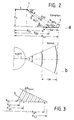
- FIGS. 2a and 2b This lighting geometry is shown in more detail in elevation or azimuth in FIGS. 2a and 2b.
- the inner edge of the illuminated circular ring 4 with the stripe width SW lies on the ground at a distance R G1 from the projected center of the helicopter, the distance between the antenna being R S1 .
- R S1 With Theta1 is the Depression angle between the antenna and this point.
- the sizes R G2 , R S2 and Theta2 apply to the corresponding point on the outer edge of the illuminated ring 4.
- R G0 and R S0 apply to the point on the ground with regard to the central viewing direction of the antenna with the depression angle Theta.
- the difference between R S2 and R S1 is marked in FIG. 2 with delta R S.
- the strip width of the circular ring between R G1 and R G2 is divided into individual radially equal distance intervals 6, the radial centers of which are at the distances R g1 , R g2 to R gN .
- the total number of these distance intervals 6 is N. This number depends on the minimum radial resolution Delta R Smin .
- a block diagram of a processor for a ROSAR device is described, the upper half of the block diagram showing those blocks which are necessary for generating the reference functions, and in the lower half those blocks which are used to receive those on the ground serve reflected signals.
- the reference signals and the received signals are correlated in a correlator 7 and sent to a memory 8, e.g. on a magnetic tape. An additional display on a monitor 9 is possible.
- a geometry module 10 is provided for determining the reference functions, a module 11 for determining the number of distance intervals, a module 12 for specifying the individual distance intervals, a module 13 for specifying the integration time, and a module 14 for specifying support points for the reference functions and finally a module 15 for determining the reference functions from the supplied data for the individual distance intervals.
- These reference functions are fed to a memory 16, which supplies the reference signals to the correlator 7.
- the treatment of the received signals S E is essentially conventional.
- the stored received signal is fed as an intermediate frequency signal to a quadrature demodulator 21 and through Quadrature mixture processed and broken down into an in-phase component of the echo signal I e and a quadrature component Q e of the echo signal.
- the operation of the entire processor is controlled by a clock generator 27, which outputs a clock signal C1 to the modules for generating the reference function as well as to the modules for processing the received signals and to the correlator.
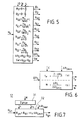
- FIG. 5 shows the geometry module 10, specifically on the basis of the function variables to be calculated in it, which it determines from input variables and calculates corresponding output variables therefrom.
- Input variables are the height above ground H O , the depression angle theta, the opening angle epsilon of the antennas in elevation and the distance of the antenna from the fulcrum, ie the length L of the rotor blade.
- the echo duration t e and the number N of the distance intervals within the illuminated strip are calculated in the module 11 using the formulas given.
- the antenna characteristic C must also be specified as an input variable.
- the number N corresponds to the number of resolution cells in accordance with the individual range intervals R g1 to R gN in the radial direction on the ground in accordance with FIG. 3.
- the module 12 calculates the actual values for the individual distance intervals R gn from the input variable R G1 supplied by the geometry module 10 and the number N from the module 11, as shown in FIG. 7.
- the number N of distance intervals is fed to a counter 31, which calculates an output value x n from the input value n to N, which is reduced by the value 1/2 compared to the input value.
- the output signals of the counter 31 are fed together with the signal Delta R Smin for the radial resolution and the signal R G1 to a function block 32 in which the values R gn for the individual distance intervals are calculated according to the formula given.
- module 13 This module also receives the assigned number n of the total N distance intervals via a counter 33 and calculates from these values and the opening angle gamma of the antenna in azimuth, the length L of the rotor blade and the angular velocity omega zero of the rotor blade according to those in FIG. 8 given formulas, the synthetic aperture S, the integration time T S and the angle of rotation range Alpha S of the integration, in each case for one of the distance intervals, which is indicated by the index n. This index runs from 1 to N.
- the number of support points which depends on the pulse repetition frequency and the integration time, determines the capacity of the memory 16 for the reference functions.
- the memory is designed for the maximum number of support points, i.e. for a number that is present along the outer edge of the strip of the illuminated annulus.
- the step size Delta Alpha of the base values corresponding to a respective angular range for the integration is directly assigned to this number of base points.
- the reference functions S R in the module 15 according to FIG. 10 can then be calculated from the values R gn , delta alpha, Z Sn and the antenna height H0 above ground using the formulas given there.
- the wavelength lambda, the rotor blade length L and the number of circles are specified for this calculation.
- the calculation is carried out in a function block 36, to which the number n of the respective distance interval is also fed via a counter 37.
- the reference function S R is composed of a real part I R and an imaginary part Q R. This applies to each distance interval 1 to N, which is expressed by the further index n.
- the formulas on which this calculation is based are specified in function block 36 in accordance with FIG. 10 as sample values marked with a roof. The calculation of the reference functions takes place for all distance intervals, so that the samples are summed up by the number Z S of the transmission pulses.
- the reference functions determined for all distance intervals are fed to the memory 16, the structure of which is shown schematically in FIG. 11a.
- This memory is divided into rows and columns, with a reference function for a distance interval being stored in each row.
- the number of lines is determined by the number N of Distance intervals determine the number of columns by the number Z SN of the support points over the aperture length taken into account.
- the number of support points is determined by the desired overall viewing angle of the radar device, which is, for example, 180 ° if only detection of targets in the forward direction, based on the flight direction of the helicopter, is desired.
- the capacitance K R is determined by the product of the total number Z SN of the support points, the number Z A of samples in the radial direction and twice the value of the word length U of the digitally converted signals, since these are available as complex values.
- the samples of the received signals are recorded in memory 26 as shown in FIG. 11b.
- the storage capacity K E of this memory 26 is determined by the product of the number Z B of the transmission pulses in the lateral direction, the number Z A of the samples in the radial direction and again twice the word length U of the digitally converted received signals.
- the real and imaginary values of the received signals supplied by the memory 26 are compared with the corresponding values of the reference functions and are complexly cross-correlated for each distance interval under consideration.
- the respective number of the distance interval under consideration is supplied as a default via a counter 41, and the angular velocity omega-zero of the rotor blade, the number Z B of the transmission pulses in the lateral direction corresponding to the number of reference values and the respective step size delta alpha are also given as default values of the base values for the Doppler scanning and the reference function.
- the correlation results for the individual scans are output as result signals ⁇ on (t) to the memory 8 or the monitor 9.
- the correlation is calculated in real time for all values of the input parameters.
- the function calculations within the geometry module 10 can be simplified. This then also results in a simpler calculation of the reference function, which results directly from the formulas given. From this, a first approximation can be made for the calculation of the reference function and the correlation by a simpler circuit, which is represented by block 51 in FIG. 13. If R G0 is also very large compared to L and at the same time compared to the height H der of the antenna above the ground, the formulas given can be further simplified.
- the circuits for generating the reference function can be hard-wired and are represented in FIG. 13 by the function block 52. Only for the remaining cases, ie essentially for the detection of targets in the close range, the complete solution indicated above must be used.
- the ROSAR device on a helicopter for example for navigation support, the majority of all navigation tasks can be performed with the proximity solutions, ie essentially with hard-wired circuits.
- a kinematic sensor 61 made up of two acceleration sensors 62 and 63 is arranged at each of the blade tips, the vertical runout being determined with the acceleration sensor 62 and deviations from the constant angular gel speed being determined with the acceleration sensor 63.
- the temporal fluctuations in the height of the antenna above ground can be achieved by double integration with the signals detected by the acceleration sensor 62 are determined, whereas the deviations in the angular frequency are recorded by simply integrating the signals from the acceleration sensor 63 divided by the rotor blade length.
- both the transmitter antennas and the receive antennas are located at the blade tips of the rotor. It is indeed possible to transmit the energy required to operate the transmitter antennas from the helicopter cell to the antennas via a rotary coupling. However, it is also possible, as shown in Fig. 15, to fix the transmitter antenna 71, e.g. to be mounted on the rotor masts of the helicopter and only to integrate the receiving antenna 72 into the blade tip of the rotor 2. Now that the Doppler information is only generated via the rotating receiving antennas and not additionally via the transmitter antenna, the formulas given above can be divided by a factor of 2 with otherwise the same parameters regarding the Doppler information.
- the energy transmission between the receiving antenna 72 and the evaluation circuit 73 of the ROSAR device takes place wirelessly, and preferably opto-electronically.
- the receiving antenna is connected to an optoelectronic coupler 74, which converts the electrical signals of the antenna into optical signals which transmit via optical fibers 75 within the rotor blade and which cooperate with a photodetector arrangement 76 in the region of the axis of rotation of the rotor blade.
- the photodetector arrangement 76 is associated with an arrangement 77 of optoelectronic couplers which convert the light signals into electrical signals and feed them to the evaluation circuit 73.
- the energy transmission between the fuselage and the antenna also takes place wirelessly, for example with the aid of a ring slot line or a laser arrangement, not shown here.
- the arrangement 76 also contains active laser transmitter diodes, the light of which is coupled into the optical fibers 75 and converted back into electrical energy for the optoelectronic coupler 74 in the region of the blade tip. This is shown schematically in FIG. 16.
- the laser radiation emitted by the laser diodes of the arrangement 76 is transmitted into the blade via a lens arrangement 78 in the region of the axis of rotation of the rotor, is received there with the aid of a laser diode 79 and is converted back into electrical energy in an opto-electronic converter 80, which a receiver 81 der Transmitting antenna 72 and the opto-electronic coupler 74 is supplied.
- the received signals from the antenna 72 are fed to the receiver 81, then converted opto-electronically in the coupler 74 and modulated in a modulator 82. These modulated signals are emitted with a diode 83, bundled via a lens arrangement 84 and conducted to the receiving diodes of the photodetector arrangement 76.
- the transmitter antenna and the receiving antenna arranged on the helicopter fuselage should have essentially the same antenna diagrams and e.g. have a horizontal opening angle of 180 °. This characteristic of the transmitter antenna means that only the area in front of the helicopter can be imaged.
- the signals of the kinematics sensor 61 are passed to the evaluation unit 73 and used to correct the reference functions.
- the received signal is converted to an intermediate frequency coherently with the emitted transmission frequency and transmitted to the photodetector unit 76 with the aid of the light modulator and the laser transmission diode via the laser transmission path.
- the evaluation unit 73 can be fed with both the total signal received by the receiving antenna 72 and the correction signals for the reference functions for half a revolution of the rotor blade.
Landscapes
- Engineering & Computer Science (AREA)
- Remote Sensing (AREA)
- Radar, Positioning & Navigation (AREA)
- Computer Networks & Wireless Communication (AREA)
- Physics & Mathematics (AREA)
- General Physics & Mathematics (AREA)
- Electromagnetism (AREA)
- Radar Systems Or Details Thereof (AREA)
- Arrangements For Transmission Of Measured Signals (AREA)
Applications Claiming Priority (2)
| Application Number | Priority Date | Filing Date | Title |
|---|---|---|---|
| DE3922086 | 1989-07-05 | ||
| DE3922086A DE3922086C1 (enExample) | 1989-07-05 | 1989-07-05 |
Publications (3)
| Publication Number | Publication Date |
|---|---|
| EP0406522A2 EP0406522A2 (de) | 1991-01-09 |
| EP0406522A3 EP0406522A3 (en) | 1991-12-27 |
| EP0406522B1 true EP0406522B1 (de) | 1994-11-23 |
Family
ID=6384347
Family Applications (1)
| Application Number | Title | Priority Date | Filing Date |
|---|---|---|---|
| EP90104498A Expired - Lifetime EP0406522B1 (de) | 1989-07-05 | 1990-03-09 | Radargerät mit synthetischer Apertur auf der Basis rotierender Antennen |
Country Status (7)
| Country | Link |
|---|---|
| US (1) | US5017922A (enExample) |
| EP (1) | EP0406522B1 (enExample) |
| JP (1) | JP2643007B2 (enExample) |
| KR (1) | KR0142668B1 (enExample) |
| AU (1) | AU626220B2 (enExample) |
| DE (1) | DE3922086C1 (enExample) |
| ES (1) | ES2066892T3 (enExample) |
Families Citing this family (43)
| Publication number | Priority date | Publication date | Assignee | Title |
|---|---|---|---|---|
| DE4233415C2 (de) * | 1992-10-05 | 1994-07-14 | Deutsche Aerospace | Radargerät mit synthetischer Apertur auf der Basis rotierender Antennen |
| DE4233416C2 (de) * | 1992-10-05 | 1994-09-08 | Deutsche Aerospace | Radargerät mit synthetischer Apertur auf der Basis rotierender Antennen |
| DE4235071C2 (de) * | 1992-10-17 | 1995-09-28 | Daimler Benz Aerospace Ag | Radargerät mit synthetischer Apertur auf der Basis rotierender Antennen |
| DE4235072C2 (de) * | 1992-10-17 | 1995-09-28 | Daimler Benz Aerospace Ag | Radargerät mit synthetischer Apertur auf der Basis rotierender Antennen |
| DE4242532C2 (de) * | 1992-12-16 | 1995-10-26 | Daimler Benz Aerospace Ag | Radargerät mit synthetischer Apertur auf der Basis rotierender Antennen |
| DE4304027C2 (de) * | 1993-02-11 | 1996-05-02 | Daimler Benz Aerospace Ag | Radargerät mit synthetischer Apertur auf der Basis rotierender Antennen |
| DE4306920C2 (de) * | 1993-03-05 | 1995-03-30 | Deutsche Aerospace | Radargerät mit synthetischer Apertur auf der Basis rotierender Antennen |
| GB2517659B (en) * | 1993-06-23 | 2015-07-22 | Dassault Electronique | Radar for helicopters |
| DE4323511C1 (de) * | 1993-07-14 | 1995-01-26 | Deutsche Aerospace | Radargerät zur Hinderniswarnung |
| FR2728094A1 (fr) * | 1994-12-07 | 1996-06-14 | Dassault Electronique | Dispositif de detection et de localisation d'objets au sol |
| DE19528613C2 (de) * | 1995-08-04 | 1998-07-02 | Daimler Benz Aerospace Ag | Einrichtung zur Bewegungsfehler-Kompensation für ein Radar mit synthetischer Apertur auf der Basis rotierender Antennen (ROSA) für Hubschrauber |
| US5614907A (en) * | 1996-03-14 | 1997-03-25 | Daimler-Benz Aerospace Ag | All weather visual system for helicopters |
| DE19851910C1 (de) * | 1998-11-11 | 2000-12-07 | Horst Kaltschmidt | Verfahren und Einrichtung zur Durchführung desselben bei einem ROSAR-System |
| DE19902008C2 (de) * | 1999-01-21 | 2001-04-12 | Daimler Chrysler Ag | Anordnung zur interferometrischen Radarmessung nach dem ROSAR-Prinzip |
| DE19902007C2 (de) * | 1999-01-21 | 2002-06-27 | Daimler Chrysler Ag | Verfahren und Anordnung zur interferometrischen Radarmessung |
| US7002508B2 (en) | 1999-01-21 | 2006-02-21 | Eads Deutschland Gmbh | Method for interferometric radar measurement |
| DE19945791C1 (de) * | 1999-09-24 | 2001-05-17 | Daimler Chrysler Ag | Hubschraubergetragene Radaranlage |
| DE10010134B4 (de) * | 2000-03-03 | 2006-08-31 | Eads Deutschland Gmbh | Telematik-Verfahren für Hubschrauber |
| DE10035658C2 (de) * | 2000-07-20 | 2002-06-27 | Joao R Moreira | Vorwärtssicht-Radarsystem (FLR; Forward Looking Radar) zur dreidimensionalen Abbildung eines Geländeausschnitts |
| US6626078B2 (en) * | 2000-11-30 | 2003-09-30 | Lockheed Martin Corporation | Apparatus for detecting, identifying, and validating the existence of buried objects |
| DE10101990C2 (de) * | 2001-01-18 | 2003-01-09 | Eads Deutschland Gmbh | Verfahren zur Drahterkennung auf der Basis des ROSAR-Systems |
| DE10101992C2 (de) * | 2001-01-18 | 2002-12-05 | Eads Deutschland Gmbh | Radarverfahren zur Erkennung und Endeckung verdeckter Ziele |
| DE10101989C2 (de) * | 2001-01-18 | 2002-12-05 | Eads Deutschland Gmbh | Stromversorgungssystem für ROSAR-Transponder |
| DE10101991C1 (de) * | 2001-01-18 | 2002-06-20 | Eads Deutschland Gmbh | Verfahren zur Signalverarbeitung- und Prozessierung nach dem ROSAR-System |
| DE10120537C2 (de) * | 2001-04-26 | 2003-12-18 | Eads Deutschland Gmbh | Verfahren zur Erkennung und Identifizierung von Objekten mittels mehrerer in einem Flugzeug vorhandener Sensoren |
| DE10120536C2 (de) * | 2001-04-26 | 2003-12-24 | Eads Deutschland Gmbh | Radarsystem zur aktiven Hinderniswarnung und Abbildung der Erdoberfläche |
| DE10348981B4 (de) * | 2003-10-22 | 2009-04-09 | Eurocopter Deutschland Gmbh | Rotor, insbesondere für ein Drehflugzeug |
| DE102004005399A1 (de) * | 2004-02-03 | 2005-08-25 | Eads Deutschland Gmbh | Verfahren zur Verbesserung der Lateralauflösung eines ROSAR-Systems |
| DE102004061486B4 (de) * | 2004-12-21 | 2007-04-05 | Eads Deutschland Gmbh | Verfahren zur Signaldatenverarbeitung eines fluggerätegetragenen Radars mit synthetischer Apertur und eine Vorrichtung dafür |
| US7528762B2 (en) * | 2005-03-31 | 2009-05-05 | Southwest Research Institute | Signal processing methods for ground penetrating radar from elevated platforms |
| KR100740115B1 (ko) * | 2005-12-20 | 2007-07-16 | 한국항공우주연구원 | 헬리콥터 야간비행을 위한 레이저를 이용한 장애물 인식시스템 |
| DE102006037898B3 (de) * | 2006-08-11 | 2008-03-27 | Eads Deutschland Gmbh | Radargerät für einen Drehflügler |
| US7928901B2 (en) * | 2008-10-16 | 2011-04-19 | The United States Of America As Represented By The Secretary Of The Army | Systems and methods for producing radar images |
| ES2374684T3 (es) * | 2008-12-02 | 2012-02-21 | Thales Nederland B.V. | Un sistema de vigilancia que comprende una antena de radar montada sobre un aspa de un aerogenerador. |
| JP5634238B2 (ja) * | 2010-12-06 | 2014-12-03 | 三菱電機株式会社 | レーダ装置 |
| US8960593B2 (en) * | 2011-05-03 | 2015-02-24 | Raytheon Company | Horizon scanning system for a rotary wing aircraft including sensors housed within a tubercle on a rotor blade |
| KR101273102B1 (ko) * | 2011-12-20 | 2013-06-13 | 홍익대학교 산학협력단 | 지상운용 회전형 sar 장치 |
| EP3312631B1 (en) * | 2012-12-10 | 2020-08-12 | AIRBUS HELICOPTERS DEUTSCHLAND GmbH | A rotorcraft with an obstacle and terrain warning radar system |
| US9128184B1 (en) * | 2013-03-14 | 2015-09-08 | Lockheed Martin Corporation | Radar wind turbine |
| BR102014006109B1 (pt) * | 2014-03-14 | 2021-10-19 | Embraer S.A. | Radar de alta precisão para acompanhamento de alvos aéreos |
| KR101715230B1 (ko) * | 2015-03-16 | 2017-03-13 | 주식회사 에이치시티엠 | 회전체에 설치되는 무지향성 안테나 |
| US10495751B2 (en) | 2015-11-27 | 2019-12-03 | Bradar Industria S.A. | System and method for detecting and visualizing targets by airborne radar |
| DE102020121980B3 (de) | 2020-08-21 | 2021-10-21 | Audi Aktiengesellschaft | Kraftfahrzeug mit wenigstens einem Radarsensor und Verfahren zum Betrieb eines Kraftfahrzeugs |
Family Cites Families (5)
| Publication number | Priority date | Publication date | Assignee | Title |
|---|---|---|---|---|
| FR2400714A1 (fr) * | 1977-08-19 | 1979-03-16 | Thomson Csf | Radar de cartographie |
| DE3409809A1 (de) * | 1984-03-16 | 1985-09-19 | Siemens AG, 1000 Berlin und 8000 München | Sende- und/oder empfangseinrichtung fuer elektromagnetische strahlung |
| US4638315A (en) * | 1984-06-20 | 1987-01-20 | Westinghouse Electric Corp. | Rotor tip synthetic aperture radar |
| US4737788A (en) * | 1985-04-04 | 1988-04-12 | Motorola, Inc. | Helicopter obstacle detector |
| DE3712065C1 (de) * | 1987-04-09 | 1988-09-22 | Dornier System Gmbh | Verfahren zur topografischen Kartierung |
-
1989
- 1989-07-05 DE DE3922086A patent/DE3922086C1/de not_active Expired - Lifetime
-
1990
- 1990-03-09 EP EP90104498A patent/EP0406522B1/de not_active Expired - Lifetime
- 1990-03-09 ES ES90104498T patent/ES2066892T3/es not_active Expired - Lifetime
- 1990-03-28 AU AU52309/90A patent/AU626220B2/en not_active Ceased
- 1990-05-09 JP JP2117788A patent/JP2643007B2/ja not_active Expired - Fee Related
- 1990-06-07 US US07/534,284 patent/US5017922A/en not_active Expired - Lifetime
- 1990-07-03 KR KR1019900009993A patent/KR0142668B1/ko not_active Expired - Fee Related
Also Published As
| Publication number | Publication date |
|---|---|
| EP0406522A3 (en) | 1991-12-27 |
| DE3922086C1 (enExample) | 1990-10-18 |
| AU5230990A (en) | 1991-01-10 |
| JPH0344590A (ja) | 1991-02-26 |
| JP2643007B2 (ja) | 1997-08-20 |
| KR910003399A (ko) | 1991-02-27 |
| EP0406522A2 (de) | 1991-01-09 |
| KR0142668B1 (ko) | 1998-08-17 |
| AU626220B2 (en) | 1992-07-23 |
| ES2066892T3 (es) | 1995-03-16 |
| US5017922A (en) | 1991-05-21 |
Similar Documents
| Publication | Publication Date | Title |
|---|---|---|
| DE3922086C1 (enExample) | ||
| EP0634668B1 (de) | Radargerät zur Hinderniswarnung | |
| EP2293013B1 (de) | 3D-Laservermessungseinrichtung | |
| DE3887667T2 (de) | Radioelektrischer Sensor zur Erstellung einer radioelektrischen Karte einer Landschaft. | |
| EP0757259B1 (de) | Einrichtung zur Bewegungsfehler-Kompensation für ein Radar mit synthetischer Apertur auf der Basis rotierender Antennen (ROSAR) für Hubschrauber | |
| DE60218307T2 (de) | Ladar system mit synthetischer aperture und inkohärenten laserimpulsen | |
| DE3731037A1 (de) | Laser-abbildungssystem mit detektorzeile | |
| DE10231661B4 (de) | Abbildung von Meeresoberflächenströmungen mit bistatischem HF-Radar | |
| DE69514560T2 (de) | Verfahren zur Bewertung der Bildqualität bei einem Radar mit synthetischer Apertur | |
| DE69019292T2 (de) | Dauerstrich-FM-Radargerät. | |
| DE102020123293A1 (de) | Verfahren, Radarsystem und Fahrzeug zur Signalverarbeitung von Radarsignalen | |
| EP0591652B1 (de) | Radargerät mit synthetischer Apertur auf der Basis rotierender Antennen | |
| DE102023205823A1 (de) | Verfahren zum entwerfen eines radoms einer radarvorrichtung, radom und radarvorrichtung, für die es verwendet wird | |
| DE2835932A1 (de) | Kartographieradargeraet | |
| EP1515159A1 (de) | Verfahren zur Verringerung des Dopplerzentroids bei einem kohärenten Impuls-Radarsystem | |
| DE2133395B2 (de) | Einrichtung zur Kompensation deer Eigenbewegung einer kohärenten Impuls-Doppler-Radaranlage | |
| DE202019105270U1 (de) | System zur Herleitung von Seestatusparametern | |
| EP0445794A2 (de) | Vorwärtssicht-Radar | |
| EP0591651B1 (de) | Radargerät mit synthetischer Apertur auf der Basis rotierender Antennen | |
| DE4304027C2 (de) | Radargerät mit synthetischer Apertur auf der Basis rotierender Antennen | |
| EP0910806B1 (de) | Verfahren zur überwachung der erdoberfläche | |
| DE3782641T2 (de) | Radar zielverfolgungssystem, das radiowellen im millimeterbereich verwendet. | |
| DE1110448B (de) | Doppler-Radarsystem | |
| EP1004895B1 (de) | Verfahren zur Verringerung des Rechenaufwandes und Einrichtung zur Durchführung desselben in einem ROSAR-System | |
| EP0076877B1 (de) | Einrichtung zur Darstellung eines Geländeausschnitts an Bord von Fahrzeugen, insbesondere Luftfahrzeugen |
Legal Events
| Date | Code | Title | Description |
|---|---|---|---|
| PUAI | Public reference made under article 153(3) epc to a published international application that has entered the european phase |
Free format text: ORIGINAL CODE: 0009012 |
|
| 17P | Request for examination filed |
Effective date: 19901116 |
|
| AK | Designated contracting states |
Kind code of ref document: A2 Designated state(s): ES FR GB IT NL SE |
|
| PUAL | Search report despatched |
Free format text: ORIGINAL CODE: 0009013 |
|
| AK | Designated contracting states |
Kind code of ref document: A3 Designated state(s): ES FR GB IT NL SE |
|
| RAP1 | Party data changed (applicant data changed or rights of an application transferred) |
Owner name: DEUTSCHE AEROSPACE AKTIENGESELLSCHAFT |
|
| 17Q | First examination report despatched |
Effective date: 19940309 |
|
| GRAA | (expected) grant |
Free format text: ORIGINAL CODE: 0009210 |
|
| AK | Designated contracting states |
Kind code of ref document: B1 Designated state(s): ES FR GB IT NL SE |
|
| ET | Fr: translation filed | ||
| EAL | Se: european patent in force in sweden |
Ref document number: 90104498.2 |
|
| ITF | It: translation for a ep patent filed | ||
| GBT | Gb: translation of ep patent filed (gb section 77(6)(a)/1977) |
Effective date: 19950203 |
|
| RAP2 | Party data changed (patent owner data changed or rights of a patent transferred) |
Owner name: DAIMLER-BENZ AEROSPACE AKTIENGESELLSCHAFT |
|
| REG | Reference to a national code |
Ref country code: ES Ref legal event code: FG2A Ref document number: 2066892 Country of ref document: ES Kind code of ref document: T3 |
|
| NLT2 | Nl: modifications (of names), taken from the european patent patent bulletin |
Owner name: DAIMLER-BENZ AEROSPACE AKTIENGESELLSCHAFT TE MUENC |
|
| PLBE | No opposition filed within time limit |
Free format text: ORIGINAL CODE: 0009261 |
|
| STAA | Information on the status of an ep patent application or granted ep patent |
Free format text: STATUS: NO OPPOSITION FILED WITHIN TIME LIMIT |
|
| 26N | No opposition filed | ||
| REG | Reference to a national code |
Ref country code: GB Ref legal event code: IF02 |
|
| PGFP | Annual fee paid to national office [announced via postgrant information from national office to epo] |
Ref country code: SE Payment date: 20070313 Year of fee payment: 18 Ref country code: NL Payment date: 20070313 Year of fee payment: 18 |
|
| PGFP | Annual fee paid to national office [announced via postgrant information from national office to epo] |
Ref country code: ES Payment date: 20070329 Year of fee payment: 18 |
|
| PGFP | Annual fee paid to national office [announced via postgrant information from national office to epo] |
Ref country code: GB Payment date: 20080320 Year of fee payment: 19 Ref country code: IT Payment date: 20080321 Year of fee payment: 19 |
|
| PGFP | Annual fee paid to national office [announced via postgrant information from national office to epo] |
Ref country code: FR Payment date: 20080314 Year of fee payment: 19 |
|
| EUG | Se: european patent has lapsed | ||
| PG25 | Lapsed in a contracting state [announced via postgrant information from national office to epo] |
Ref country code: NL Free format text: LAPSE BECAUSE OF NON-PAYMENT OF DUE FEES Effective date: 20081001 |
|
| NLV4 | Nl: lapsed or anulled due to non-payment of the annual fee |
Effective date: 20081001 |
|
| PG25 | Lapsed in a contracting state [announced via postgrant information from national office to epo] |
Ref country code: SE Free format text: LAPSE BECAUSE OF NON-PAYMENT OF DUE FEES Effective date: 20080310 |
|
| REG | Reference to a national code |
Ref country code: ES Ref legal event code: FD2A Effective date: 20080310 |
|
| PG25 | Lapsed in a contracting state [announced via postgrant information from national office to epo] |
Ref country code: ES Free format text: LAPSE BECAUSE OF NON-PAYMENT OF DUE FEES Effective date: 20080310 |
|
| GBPC | Gb: european patent ceased through non-payment of renewal fee |
Effective date: 20090309 |
|
| REG | Reference to a national code |
Ref country code: FR Ref legal event code: ST Effective date: 20091130 |
|
| PG25 | Lapsed in a contracting state [announced via postgrant information from national office to epo] |
Ref country code: GB Free format text: LAPSE BECAUSE OF NON-PAYMENT OF DUE FEES Effective date: 20090309 Ref country code: FR Free format text: LAPSE BECAUSE OF NON-PAYMENT OF DUE FEES Effective date: 20091123 |
|
| PG25 | Lapsed in a contracting state [announced via postgrant information from national office to epo] |
Ref country code: IT Free format text: LAPSE BECAUSE OF NON-PAYMENT OF DUE FEES Effective date: 20090309 |