EP0406484A1 - Mounting for lenses especially for looking glass to be coated in an apparatus for high vacuum evaparation or for sputtering - Google Patents
Mounting for lenses especially for looking glass to be coated in an apparatus for high vacuum evaparation or for sputtering Download PDFInfo
- Publication number
- EP0406484A1 EP0406484A1 EP89122630A EP89122630A EP0406484A1 EP 0406484 A1 EP0406484 A1 EP 0406484A1 EP 89122630 A EP89122630 A EP 89122630A EP 89122630 A EP89122630 A EP 89122630A EP 0406484 A1 EP0406484 A1 EP 0406484A1
- Authority
- EP
- European Patent Office
- Prior art keywords
- ring
- lens
- rings
- lens holder
- holder according
- Prior art date
- Legal status (The legal status is an assumption and is not a legal conclusion. Google has not performed a legal analysis and makes no representation as to the accuracy of the status listed.)
- Granted
Links
- 238000004544 sputter deposition Methods 0.000 title claims abstract description 4
- 239000011521 glass Substances 0.000 title abstract 2
- 239000000758 substrate Substances 0.000 claims abstract description 25
- 238000000034 method Methods 0.000 claims abstract description 7
- 238000000576 coating method Methods 0.000 claims abstract description 5
- 239000011248 coating agent Substances 0.000 claims abstract description 4
- 238000007738 vacuum evaporation Methods 0.000 claims abstract description 4
- 210000002105 tongue Anatomy 0.000 claims description 13
- 230000008878 coupling Effects 0.000 description 2
- 238000010168 coupling process Methods 0.000 description 2
- 238000005859 coupling reaction Methods 0.000 description 2
- 238000009792 diffusion process Methods 0.000 description 2
- 238000001704 evaporation Methods 0.000 description 2
- 239000002184 metal Substances 0.000 description 2
- 238000001771 vacuum deposition Methods 0.000 description 2
- 239000011247 coating layer Substances 0.000 description 1
- 230000008020 evaporation Effects 0.000 description 1
- 230000003287 optical effect Effects 0.000 description 1
Images

Classifications
-
- C—CHEMISTRY; METALLURGY
- C23—COATING METALLIC MATERIAL; COATING MATERIAL WITH METALLIC MATERIAL; CHEMICAL SURFACE TREATMENT; DIFFUSION TREATMENT OF METALLIC MATERIAL; COATING BY VACUUM EVAPORATION, BY SPUTTERING, BY ION IMPLANTATION OR BY CHEMICAL VAPOUR DEPOSITION, IN GENERAL; INHIBITING CORROSION OF METALLIC MATERIAL OR INCRUSTATION IN GENERAL
- C23C—COATING METALLIC MATERIAL; COATING MATERIAL WITH METALLIC MATERIAL; SURFACE TREATMENT OF METALLIC MATERIAL BY DIFFUSION INTO THE SURFACE, BY CHEMICAL CONVERSION OR SUBSTITUTION; COATING BY VACUUM EVAPORATION, BY SPUTTERING, BY ION IMPLANTATION OR BY CHEMICAL VAPOUR DEPOSITION, IN GENERAL
- C23C14/00—Coating by vacuum evaporation, by sputtering or by ion implantation of the coating forming material
- C23C14/22—Coating by vacuum evaporation, by sputtering or by ion implantation of the coating forming material characterised by the process of coating
- C23C14/50—Substrate holders
- C23C14/505—Substrate holders for rotation of the substrates
Definitions
- the invention relates to a lens holder, in particular holder for eyeglass lenses to be coated in a high vacuum evaporation system or sputtering system, which is essentially designed as a ring supporting the lens to be held, which in turn can be connected to a carrier plate which is in the process chamber of the high vacuum system in the vicinity of the coating source.
- a vacuum coating system for evaporating coating layers on optical substrates (DE-OS 37 15 831), such as plastic spectacle lenses, is known can be clamped onto carrier means that circulate in an evacuable recipient above evaporation sources, the carrier means comprising a plurality of at least approximately circular segment-shaped, flat carrier plates which are supported in a dome-shaped manner and are each rotatable by 180 ° on a common axis of rotation, each carrier plate in opening areas Has a plurality of substrate holders provided with at least one retaining spring, at least one of which can be freely tilted out of the carrier plate plane up to a predetermined angle on both sides.
- Each freely tiltable substrate holder has a frame that partially encompasses the substrate to be accommodated, in which the substrate is under the action of the retaining spring and which is attached to the support plate so that it can be tilted freely on both sides via a tilting axis.
- a lens holder in particular holder for spectacle lens lenses to be cleaned and subsequently coated (EU-PS 0 215 261) is known, which is designed as a ring carrying forks on its inside for receiving the lenses to be held, the ring being elastically deformable and the forks are arranged on two opposite sections of the ring inside.
- the present invention has for its object to provide a lens holder that allows a particularly rapid exchange of lenses that the lenses in a particularly narrow area on their outside holds edges securely and which allows the lens to be turned quickly with respect to the coating source, the respective outer surface of the lens facing the source being at the same distance from the source as the other outer surface of the lens after turning.
- this object is achieved in that the lens is inserted between two rings which are braced against one another via resilient tongues or arms, the first ring being provided on its outer circumferential surface with cams, ramps or scenes or with rags extending in the axial direction which have grooves on its inner side which cooperate with resilient tongues or arms which are fastened to the outer lateral surface of the second ring and each extend essentially in each case along the lateral surface of the ring.
- At least one of the two rings is preferably provided on its radially inner lateral surface with a circumferential groove, a chamfer or with projections which extend radially inwards and on which the outer edge of the lens is supported.
- At least one of the rings has on its radially outer circumferential surface two diametrically opposed pins or fingers with which it is supported in corresponding bearing forks which are attached to the substrate carrier.
- one of the two rings is on his radially outer circumferential surface with at least two diametrically opposed grooves, the longitudinal extensions of which extend at an angle of approximately 30 ° to the axis of rotation of the ring, resilient tongues of wire ends being provided, one end of which is soldered, welded or riveted to the ring and the other end of which is bent into a bay or loop which extends in a plane which runs parallel to the plane of the groove interacting with it.
- At least one of the pins has a cam or finger which interacts with a pair of magnets arranged on the substrate carrier in the area of the associated bearing fork in such a way that the ring or the pair of rings only two positions which are stable with respect to undesired turning or turning movements or occupies positions.
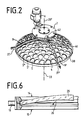
- the high-vacuum deposition system shown in FIG. 1 essentially consists of a recipient 3 with an evaporator source arranged in it, but not shown in more detail, a dome-shaped substrate holder 4 made of a sheet metal blank provided with a plurality of openings 5, 5 ', ... consisting of a drive unit 8 consisting of a motor 6 with a gear 7, a slide or rake 9 rotatable about a vertical axis and mounted above the substrate holder 4 with a lifting motor 10, a backing pump set 11, a diffusion pump 12 and a vacuum valve 13.
- openings 5, 5 ', ... in the substrate holder are used to hold pairs of rings 14, 15, which are connected to each other with the help of wire springs 16, 17 and can be used via pins 18, 19 in bearing forks 20, 21, which are each in pairs in the edge regions of the openings 5, 5 ', ... the substrate holder 4 are located (but not shown in Figure 2 for clarity).
- the first of the two rings 15 is provided on its radially outer circumferential surface 22 with the two diametrically opposite pins 18, 19, the longitudinal axis 24, 24 'and the axis of rotation of the two rings approximately in the plane of contact of these two rings 14, 15 runs.
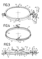
- the spectacle lens 25 is placed on the correspondingly dimensioned chamfer or flange-shaped step 26 of the second ring 15 in a first working step, then in a second working step first ring 15 placed from above on the second ring 15 so that the axes of rotation 27, 27 'of the two rings 14, 15 are aligned or coincide; in a third step, the first ring 14 is rotated relative to the second ring 15 in the direction of arrow A (FIG.
- the two clipped rings 14, 15 are now inserted with their pins 18, 19 in the direction of arrow B into the two fork-shaped or U-shaped bearing forks 20, 21, which are in pairs at each opening 5, 5 ', ... the Substrate holder 4 are.
- the outer diameter of the two rings 14, 15 and the inner diameter of the openings 5, 5 ', ... is dimensioned so that the two clipped rings 14, 15, which together form a pair of rings, in the direction of arrow C or D let the longitudinal axis 24, 24 'rotate (arrow direction C, D in Figure 5).
- This rotary or pivoting movement can be carried out with the aid of a rake 9 stored in the recipient 3 with the process chamber 34 closed.
- the rake 9 which is designed as a semicircular sheet metal blank and strokes the substrate holder 4 about the axis 33, 33 'in the manner of a comb over the top of the substrate holder 4, comes into contact with teeth one on a pin 18 of the first Rings 14 rotatably arranged gear 35 and takes this until the ring pair 14, 15 has performed a 180 ° pivoting movement about the longitudinal axis 24, 24 '.
- a provided on the pin 18 finger 36 lies on the top of the substrate holder 4 and prevents further rotation or is held in this position by one of the magnets 39, 39 ', which are in the plane of the finger 36 at a distance from each other on the Top of the substrate holder 4 are fixed.
- the rake 9 engaging in the gearwheels 35 of the respective ring pairs 14, 15 thus enables a swiveling movement of the ring pairs or the spectacle lens lenses 25 inserted into them during the ongoing coating process, ie with the recipient 3 closed, for which purpose a special lifting motor 10 with a lifting member 41 and a joint 37 is provided, which is articulated to a coupling ring 38, which connects several rakes 9, 9 'with each other, the rakes 9, 9' are connected to each other via a cam ring 40 which is slidably held and guided on the bearing tube 42 of the drive unit 8 .
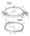
- two tabs 46, 47 are attached to the first ring 45, which parallel to the axis of rotation 57, 57 'downward , ie in the direction of the second ring 48, and which are provided on the mutually facing inner surfaces with grooves 49, 49 ', ... or 50, 50', ... or recesses with resilient tongues 43rd or 44 cooperate, which are attached to the radially outer lateral surface 53 of the second ring 48.
- the second ring 48 After inserting the spectacle lens in the second ring 48 or on the flange-shaped step 51, the second ring 48 can be screwed into the grooves 49 or 50 in the direction of arrow E, E ', depending on the thickness of the spectacle lens one of the lower or one of the upper grooves is used.
Landscapes
- Chemical & Material Sciences (AREA)
- Chemical Kinetics & Catalysis (AREA)
- Engineering & Computer Science (AREA)
- Materials Engineering (AREA)
- Mechanical Engineering (AREA)
- Metallurgy (AREA)
- Organic Chemistry (AREA)
- Physical Vapour Deposition (AREA)
- Grinding And Polishing Of Tertiary Curved Surfaces And Surfaces With Complex Shapes (AREA)
- Lens Barrels (AREA)
- Surface Treatment Of Optical Elements (AREA)
- Eyeglasses (AREA)
Abstract
Description
Die Erfindung betrifft eine Linsenhalterung, insbesondere Halterung für in einer Hochvakuum-Aufdampfanlage oder -Sputteranlage zu beschichtende Brillenglaslinsen, welche im wesentlichen als ein die zu haltende Linse tragender Ring ausgebildet ist, der seinerseits mit einer Trägerplatte verbindbar ist, die in der Prozeßkammer der Hochvakuumanlage in der Nachbarschaft der Beschichtungsquelle gehalten ist.The invention relates to a lens holder, in particular holder for eyeglass lenses to be coated in a high vacuum evaporation system or sputtering system, which is essentially designed as a ring supporting the lens to be held, which in turn can be connected to a carrier plate which is in the process chamber of the high vacuum system in the vicinity of the coating source.
Bekannt ist eine Vakuum-Beschichtungsanlage zum Aufdampfen von Vergütungsschichten auf optische Substrate (DE-OS 37 15 831), wie Kunststoff-Brillengläser, welche auf Trägermittel aufspannbar sind, die in einem evakuierbaren Rezipienten oberhalb von Verdampfungsquellen umlaufen, wobei die Trägermittel eine Mehrzahl wenigstens angenähert kreissegmentförmige, flächige Trägerplatten umfassen, welche zueinander kalottenförmig sowie je um 180° wendbar an einer gemeinsamen Drehachse abgestützt sind, wobei jede Trägerplatte in Öffnungsbereichen eine Mehrzahl mit mindestens einer Haltefeder versehene Substrathalterungen aufweist, von denen mindestens eine nach beiden Seiten aus der Trägerplattenebene bis zu einem vorgegebenen Winkel heraus frei kippbar ist.A vacuum coating system for evaporating coating layers on optical substrates (DE-OS 37 15 831), such as plastic spectacle lenses, is known can be clamped onto carrier means that circulate in an evacuable recipient above evaporation sources, the carrier means comprising a plurality of at least approximately circular segment-shaped, flat carrier plates which are supported in a dome-shaped manner and are each rotatable by 180 ° on a common axis of rotation, each carrier plate in opening areas Has a plurality of substrate holders provided with at least one retaining spring, at least one of which can be freely tilted out of the carrier plate plane up to a predetermined angle on both sides.
Jede frei kippbare Substrathalterung weist dabei eine das aufzunehmende Substrat teilweise umgreifende Fassung auf, in welcher das Substrat unter der Wirkung der Haltefeder steht und welche frei nach beiden Seiten hin kippbar über eine Kippachse an der Trägerplatte befestigt ist.Each freely tiltable substrate holder has a frame that partially encompasses the substrate to be accommodated, in which the substrate is under the action of the retaining spring and which is attached to the support plate so that it can be tilted freely on both sides via a tilting axis.
Weiterhin ist eine Linsenhalterung, insbesondere Halterung für zu reinigende und nachfolgend zu beschichtende Brillenglaslinsen bekannt (EU-PS 0 215 261), welche als ein an seiner Innenseite Gabeln zur Aufnahme der zu haltenden Linsen tragender Ring ausgebildet ist, wobei der Ring elastisch verformbar ist und die Gabeln an zwei einander gegenüberliegenden Abschnitten der Ringinnenseite angeordnet sind.Furthermore, a lens holder, in particular holder for spectacle lens lenses to be cleaned and subsequently coated (EU-PS 0 215 261) is known, which is designed as a ring carrying forks on its inside for receiving the lenses to be held, the ring being elastically deformable and the forks are arranged on two opposite sections of the ring inside.
Der vorliegenden Erfindung liegt nun die Aufgabe zugrunde, eine Linsenhalterung zu schaffen, die einen besonders raschen Austausch von Linsen erlaubt, die die Linsen in einem besonders schmalen Bereich über ihre Außen kanten sicher hält und die ein rasches Wenden der Linse gegenüber der Beschichtungsquelle erlaubt, wobei die jeweils der Quelle zugekehrte eine Außenfläche der Linse den gleichen Abstand zur Quelle haben soll wie die jeweils andere Außenfläche der Linse nach dem Wenden.The present invention has for its object to provide a lens holder that allows a particularly rapid exchange of lenses that the lenses in a particularly narrow area on their outside holds edges securely and which allows the lens to be turned quickly with respect to the coating source, the respective outer surface of the lens facing the source being at the same distance from the source as the other outer surface of the lens after turning.
Erfindungsgemäß wird diese Aufgabe dadurch gelöst, daß die Linse zwischen zwei Ringen eingelegt ist, die über federnde Zungen oder Arme gegeneinander verspannt sind, wobei der erste Ring an seiner äußeren Mantelfläche mit Nocken, Rampen oder Kulissen bzw. mit sich in axialer Richtung erstreckenden Lappen versehen ist, die an ihrer Innenseite Nuten aufweisen, die mit federnden Zungen oder Armen zusammenwirken, die an der äußeren Mantelfläche des zweiten Rings befestigt sind und sich im wesentlichen jeweils längs der Mantelfläche des Rings erstrekken.According to the invention this object is achieved in that the lens is inserted between two rings which are braced against one another via resilient tongues or arms, the first ring being provided on its outer circumferential surface with cams, ramps or scenes or with rags extending in the axial direction which have grooves on its inner side which cooperate with resilient tongues or arms which are fastened to the outer lateral surface of the second ring and each extend essentially in each case along the lateral surface of the ring.
Vorzugsweise ist zumindest einer der beiden Ringe an seiner radial inneren Mantelfläche mit einer umlaufenden Nut, einer Fase oder mit sich radial nach innen zu erstreckenden Vorsprüngen versehen, auf der der äußere Rand der Linse abgestützt ist.At least one of the two rings is preferably provided on its radially inner lateral surface with a circumferential groove, a chamfer or with projections which extend radially inwards and on which the outer edge of the lens is supported.
Um ein rasches Wenden des Ringpaares zu ermöglichen, weist zumindest einer der Ringe an seiner radial äußeren Mantelfläche zwei sich diametral gegenüberliegende Zapfen oder Finger auf, mit denen er sich in korrespondierenden Lagergabeln, die am am Substratträger angebracht sind, abstützt.In order to enable the pair of rings to be turned quickly, at least one of the rings has on its radially outer circumferential surface two diametrically opposed pins or fingers with which it is supported in corresponding bearing forks which are attached to the substrate carrier.
Damit ein sicheres Verklippen der Ringe miteinander ermöglicht wird, ist der eine der beiden Ringe an seiner radial äußeren Mantelfläche mit mindestens zwei einander diametral gegenüberliegenden Nuten versehen, deren Längserstreckungen in einem Winkel von etwa 30° zur Rotationsachse des Rings verlaufen, wobei federnde Zungen aus Drahtenden vorgesehen sind, deren jeweils eines Ende mit dem Ring fest verlötet, verschweißt oder vernietet ist und deren jeweils anderes Ende zu einer Bucht oder Schlinge gebogen ist, die sich in einer Ebene erstreckt, die parallel der Ebene der mit dieser zusammenwirkenden Nut verläuft.So that the rings can be securely clipped together, one of the two rings is on his radially outer circumferential surface with at least two diametrically opposed grooves, the longitudinal extensions of which extend at an angle of approximately 30 ° to the axis of rotation of the ring, resilient tongues of wire ends being provided, one end of which is soldered, welded or riveted to the ring and the other end of which is bent into a bay or loop which extends in a plane which runs parallel to the plane of the groove interacting with it.
Mit Vorteil weist zumindest einer der Zapfen einen Nokken oder Finger auf, der mit einem Paar im Bereich der zugehörigen Lagergabel auf dem Substratträger angeordneten Magneten in der Weise zusammenwirkt, daß der Ring bzw. das Ringpaar nur zwei gegenüber unerwünschten Dreh- bzw. Wendebewegungen stabile Lagen bzw. Positionen einnimmt.Advantageously, at least one of the pins has a cam or finger which interacts with a pair of magnets arranged on the substrate carrier in the area of the associated bearing fork in such a way that the ring or the pair of rings only two positions which are stable with respect to undesired turning or turning movements or occupies positions.
Weitere Einzelheiten und Merkmale sind in den Unteransprüchen gekennzeichnet.Further details and features are characterized in the subclaims.
Die Erfindung läßt die verschiedensten Ausführungsmöglichkeiten zu. Eine davon ist in den anhängenden Zeichnungen schematisch näher dargestellt, und zwar zeigen:
- Fig. 1 eine Hochvakuum-Aufdampfanlage, teilweise im Schnitt,
- Fig. 2 den kalottenförmig gebogenen Substratträger gemäß Figur 1 im vergrößerten Maßstab,
- Fig. 3 und 4 die beiden Ringe zur Halterung der Brillenglaslinse in perspektivischer Darstellung,
- Fig. 5 die beiden miteinander verbundenen Ringe gemäß den Figuren 3 und 4 und deren Lagerung auf dem Substratträger in der Seitenansicht,
- Fig. 6 den Teillängsschnitt durch die beiden Ringe mit eingelegter Brillenglaslinse und
- Fig. 7 und 8 eine alternative Ausführungsform der beiden Ringe zur Halterung der Brillenglaslinse in perspektivischer Darstellung.
- 1 is a high vacuum evaporation system, partly in section,
- 2 the dome-shaped substrate carrier according to FIG. 1 on an enlarged scale,
- 3 and 4, the two rings for holding the spectacle lens in a perspective view,
- 5 shows the two interconnected rings according to FIGS. 3 and 4 and their storage on the substrate carrier in a side view,
- Fig. 6 shows the partial longitudinal section through the two rings with an inserted lens and
- 7 and 8 an alternative embodiment of the two rings for holding the spectacle lens in a perspective view.
Die in Figur 1 dargestellte Hochvakuum-Aufdampfanlage besteht im wesentlichen aus einem Rezipienten 3 mit einer in diesem angeordneten, jedoch nicht näher dargestellten Verdampferquelle, einer kalottenförmig gebogenen Substrathalterung 4 aus einem mit einer Vielzahl von Öffnungen 5, 5′, ... versehenen Blechzuschnitt, aus einer aus einem Motor 6 mit Getriebe 7 bestehenden Antriebseinheit 8, einem um eine vertikale Achse drehbaren, oberhalb der Substrathalterung 4 gelagerten Schieber oder Rechen 9 mit Hubmotor 10, einem Vorpumpsatz 11, einer Diffusionspumpe 12 und einem Vakuumventil 13.The high-vacuum deposition system shown in FIG. 1 essentially consists of a recipient 3 with an evaporator source arranged in it, but not shown in more detail, a dome-
Die aus Figur 2 ersichtlichen Öffnungen 5, 5′, ... in der Substrathalterung (die nur bei einem Abschnitt der Substrathalterung dargestellt sind) dienen der Aufnahme von Ringpaaren 14, 15, die mit Hilfe von Drahtfedern 16, 17 miteinander verbunden sind und über Zapfen 18, 19 in Lagergabeln 20, 21 einsetzbar sind, die sich jeweils paarweise in den Randbereichen der Öffnungen 5, 5′, ... der Substrathalterung 4 befinden (in Figur 2 jedoch der besseren Übersichtlichkeit wegen nicht näher eingezeichnet sind). Gemäß den Figuren 3 und 5 ist der erste der beiden Ringe 15 an seiner radial äußeren Mantelfläche 22 mit den beiden einander diametral gegenüberliegenden Zapfen 18, 19 versehen, wobei die Längsachse 24, 24′ bzw. die Rotationsachse der beiden Ringe etwa in der Berührungsebene dieser beiden Ringe 14, 15 verläuft.The apparent from Figure 2
Um die Brillenglaslinse 25 in die Ringe 14, 15 einlegen und diese anschließend miteinander verbinden zu können, wird die Brillenglaslinse 25 in einem ersten Arbeitsschritt auf die entsprechend bemessene Fase bzw. flanschförmige Stufe 26 des zweiten Rings 15 aufgelegt, dann wird in einem zweiten Arbeitsschritt der erste Ring 15 von oben her auf den zweiten Ring 15 so aufgelegt, daß die Rotationsachsen 27, 27′ der beiden Ringe 14, 15 fluchten bzw. zusammenfallen; in einem dritten Arbeitsschritt wird der erste Ring 14 gegenüber dem zweiten Ring 15 in Pfeilrichtung A (Figur 3) gedreht, und zwar so lange, bis die buchtenförmigen, federnden Enden 16′, 17′ der Drahtfedern 16, 17 in die beiden Nuten 28, 29 hineingleiten, die in die radial äußere Mantelfläche 22 des ersten Rings 14 einander diametral gegenüberliegend eingeschnitten sind. Die buchtenförmigen Enden 16′, 17′ rutschen bei dieser Drehbewegung die Rampen 30, 31 der Nuten 28, 29 entlang, bis sie auf der Oberseite 32 des ersten Rings 14 aufliegen und so beide Ringe 14, 15 mit der dazwischenliegenden Brillenglaslinse 25 zusammenhalten (siehe Figur 5).In order to be able to insert the
Die beiden miteinander verklippten Ringe 14, 15 werden nun mit ihren Zapfen 18, 19 in Pfeilrichtung B in die beiden gabelförmigen bzw. U-förmigen Lagergabeln 20, 21 eingelegt, die sich paarweise jeweils an jeder Öffnung 5, 5′, ... der Substrathalterung 4 befinden. Der Außendurchmesser der beiden Ringe 14, 15 bzw. der Innendurchmesser der Öffnungen 5, 5′, ... ist dabei so bemessen, daß sich die beiden miteinander verklippten Ringe 14, 15, die zusammen ein Ringpaar bilden, in Pfeilrichtung C oder D um die Längsachse 24, 24′ drehen lassen (Pfeilrichtung C, D in Figur 5). Diese Dreh- oder Schwenkbewegung ist mit Hilfe eines im Rezipienten 3 gelagerten Rechen 9 bei geschlossener Prozeßkammer 34 durchführbar. Der Rechen 9, der als halbkreisförmiger Blechzuschnitt ausgebildet ist und bei einer Drehbewegung der Substrathalterung 4 um die Achse 33, 33′ nach Art eines Kamms über die Oberseite der Substrathalterung 4 streicht, gerät dabei in Kontakt mit Zähnen eines auf jeweils einem Zapfen 18 des ersten Rings 14 drehfest angeordneten Zahnrads 35 und nimmt dieses so lange mit, bis das Ringpaar 14, 15 eine 180° Schwenkbewegung um die Längsachse 24, 24′ vollführt hat. Ein am Zapfen 18 vorgesehener Finger 36 legt sich dabei auf die Oberseite der Substrathalterung 4 auf und verhindert eine weitere Drehbewegung bzw. wird in dieser Position von einem der Magnete 39, 39′ gehalten, die in der Ebene des Fingers 36 im Abstand zueinander auf der Oberseite der Substrathalterung 4 fest angeordnet sind. Die beiden Magnete 39, 39′ tragen dafür Sorge, daß das Ringpaar 14, 15 während des Wendevorgangs nicht in einer Zwischenposition bzw. in einer instabilen Position stehen bleibt oder nach dem Wendevorgang in diese zurückschwingt. Der in die Zahnräder 35 der jeweiligen Ringpaare 14, 15 eingreifende Rechen 9 ermöglicht also eine Schwenkbewegung der Ringpaare bzw. der in diese eingelegten Brillenglaslinsen 25 während des laufenden Beschichtungsvorgangs, d. h. bei geschlossenem Rezipienten 3, wozu ein besonderer Hubmotor 10 mit Hubglied 41 und Gelenk 37 vorgesehen ist, der dazu an einen Koppelring 38 angelenkt ist, der mehrere Rechen 9, 9′ miteinander verbindet, wobei die Rechen 9, 9′ über einen Hubring 40 miteinander verbunden sind, der auf dem Lagerrohr 42 der Antriebseinheit 8 verschiebbar gehalten und geführt ist.The two clipped
Bei der Ausführungsform der beiden Ringe 45, 48 nach den Figuren 7 und 8 sind statt der Auflauframpen 30, 31 oder Nuten 28, 29 zwei Lappen 46, 47 am ersten Ring 45 befestigt, die sich parallel zur Rotationsachse 57, 57′ nach unten zu, d. h. in Richtung auf den zweiten Ring 48 zu, erstrecken und die jeweils an den einander zugekehrten Innenflächen mit Nuten 49, 49′, ... bzw. 50, 50′, ... oder Ausnehmungen versehen sind, die mit federnden Zungen 43 bzw. 44 zusammenwirken, die an der radial äußeren Mantelfläche 53 des zweiten Rings 48 befestigt sind. Nach dem Einlegen der Brillenglaslinse in den zweiten Ring 48 bzw. auf die flanschförmige Stufe 51 kann der zweite Ring 48 in Pfeilrichtung E, E′ in die Nuten 49 bzw. 50 eingedreht werden, wobei je nach der Dicke der Brillenglaslinse jeweils eine der unteren oder eine der oberen Nuten benutzt wird.In the embodiment of the two
- 3 Rezipient3 recipient
- 4 Substrathalterung4 substrate holder
- 5, 5′, .. Öffnung5, 5 ′, .. opening
- 6 Motor6 engine
- 7 Getriebe7 gears
- 8 Antriebseinheit8 drive unit
- 9, 9′ Rechen9, 9 ′ rake
- 10 Antriebsmotor10 drive motor
- 11 Vorpumpsatz11 Backing pump set
- 12 Diffusionspumpe12 diffusion pump
- 13 Vakuumventil13 vacuum valve
- 14 erster Ring14 first ring
- 15 zweiter Ring15 second ring
- 16, 16′ Drahtfeder, federnde Zunge16, 16 'wire spring, resilient tongue
- 17, 17′ Drahtfeder, federnde Zunge17, 17 'wire spring, resilient tongue
- 18 Zapfen18 cones
- 19 Zapfen19 cones
- 20 Lagergabel20 storage fork
- 21 Lagergabel21 storage fork
- 22 radial äußere Mantelfläche22 radially outer lateral surface
- 23 radial äußere Mantelfläche23 radially outer lateral surface
- 24, 24′ Längsachse24, 24 'longitudinal axis
- 25 Brillenglaslinse25 spectacle lens
- 26 flanschförmige Stufe26 flange-shaped step
- 27, 27′ Rotationsachse27, 27 ′ axis of rotation
- 28 Nut28 groove
- 29 Nut29 groove
- 30 Rampe30 ramp
- 31 Rampe31 ramp
- 32 Ringoberseite32 top of ring
- 33 Drehachse33 axis of rotation
- 34 Prozeßkammer34 process chamber
- 35 Zahnrad35 gear
- 36 Finger36 fingers
- 37 Gelenk37 joint
- 38 Koppelring38 coupling ring
- 39, 39′ Magnet39, 39 ′ magnet
- 40 Hubring40 lifting ring
- 41 Hubglied41 lifting link
- 42 Lagerrohr42 bearing tube
- 43 Drahtfeder, federnde Zunge43 wire spring, resilient tongue
- 44 Drahtfeder, federnde Zunge44 wire spring, resilient tongue
- 45 erster Ring45 first ring
- 46 Lappen46 rags
- 47 Lappen47 rags
- 48 zweiter Ring48 second ring
- 49, 49′, ... Nut49, 49 ′, ... groove
- 50, 50′, ... Nut50, 50 ′, ... groove
- 51 flanschförmige Stufe51 flange-shaped step
- 52 radial äußere Mantelfläche52 radially outer lateral surface
- 53 radial äußere Mantelfläche53 radially outer lateral surface
- 54 Zapfen54 cones
- 55 Zapfen55 cones
- 56 Finger56 fingers
- 57, 57′ Rotationsachse57, 57 ′ axis of rotation
Claims (9)
Applications Claiming Priority (2)
| Application Number | Priority Date | Filing Date | Title |
|---|---|---|---|
| DE3921671 | 1989-07-01 | ||
| DE3921671A DE3921671A1 (en) | 1989-07-01 | 1989-07-01 | LENS HOLDER, ESPECIALLY HOLDER FOR EYE GLASS LENSES TO BE COATED IN A HIGH VACUUM VACUUM DEVICE OR SPUTTER |
Publications (2)
| Publication Number | Publication Date |
|---|---|
| EP0406484A1 true EP0406484A1 (en) | 1991-01-09 |
| EP0406484B1 EP0406484B1 (en) | 1993-06-16 |
Family
ID=6384096
Family Applications (1)
| Application Number | Title | Priority Date | Filing Date |
|---|---|---|---|
| EP89122630A Expired - Lifetime EP0406484B1 (en) | 1989-07-01 | 1989-12-08 | Mounting for lenses especially for looking glass to be coated in an apparatus for high vacuum evaparation or for sputtering |
Country Status (6)
| Country | Link |
|---|---|
| US (1) | US5124019A (en) |
| EP (1) | EP0406484B1 (en) |
| JP (1) | JP3043373B2 (en) |
| DE (2) | DE3921671A1 (en) |
| ES (1) | ES2041955T3 (en) |
| MY (1) | MY104873A (en) |
Cited By (8)
| Publication number | Priority date | Publication date | Assignee | Title |
|---|---|---|---|---|
| GB2244286A (en) * | 1990-05-22 | 1991-11-27 | Satis Vacuum Ag | Vacuum deposition apparatus for coating one side of optical substrates |
| FR2671738A1 (en) * | 1991-01-22 | 1992-07-24 | Essilor Int | RETURNABLE INDIVIDUAL BRACKET FOR APPLYING A TREATMENT TO ANY SUBSTRATE, ESPECIALLY A GLASS OF GLASSES, AND EQUIPMENT FOR THE IMPLEMENTATION OF SUCH A SUPPORT. |
| EP0547312A1 (en) * | 1991-12-19 | 1993-06-23 | Balzers Aktiengesellschaft | Substrate-holding and -turning device for vacuum processes |
| DE4446179C2 (en) * | 1994-12-23 | 2003-08-21 | Leybold Optics Gmbh | Holder for disc-shaped substrates |
| EP1950323A1 (en) * | 2007-01-25 | 2008-07-30 | Essilor International (Compagnie Generale D'optique) | Optical lens holder |
| EP3689543A1 (en) * | 2019-01-30 | 2020-08-05 | Carl Zeiss Vision International GmbH | Device and method for inserting an optical lens into a turning device |
| WO2022012955A1 (en) * | 2020-07-13 | 2022-01-20 | Carl Zeiss Vision International Gmbh | Apparatus for accommodating an article in a vacuum-coating installation |
| US12129540B2 (en) | 2019-01-30 | 2024-10-29 | Carl Zeiss Vision International Gmbh | Apparatus and method for introducing an optical lens into a turning device |
Families Citing this family (13)
| Publication number | Priority date | Publication date | Assignee | Title |
|---|---|---|---|---|
| US5660693A (en) * | 1991-01-18 | 1997-08-26 | Applied Vision Limited | Ion vapour deposition apparatus and method |
| DE4232902C2 (en) * | 1992-09-30 | 2001-06-28 | Leybold Ag | Substrate holder |
| US5437757A (en) * | 1994-01-21 | 1995-08-01 | Applied Materials, Inc. | Clamp ring for domed pedestal in wafer processing chamber |
| DE4420113A1 (en) * | 1994-06-09 | 1995-12-14 | Leybold Ag | Snap action carrier for cathodic vacuum sputtering plant |
| US5808721A (en) * | 1996-03-22 | 1998-09-15 | Gerber Optical. Inc. | Ophthalmic lens wafers and receiver for registering such wafers |
| CH691308A5 (en) * | 1996-05-10 | 2001-06-29 | Satis Vacuum Ind Vertriebs Ag | Substrate support for vacuum coating equipment. |
| US6017581A (en) * | 1997-04-18 | 2000-01-25 | Semi-Alloys Company | Method for coating lenticular articles |
| US6187159B1 (en) * | 1997-05-16 | 2001-02-13 | Hoya Corporation | Mechanism for setting optical lens base material on holder |
| FR2783055B1 (en) * | 1998-09-04 | 2000-11-24 | Essilor Int | SUPPORT FOR OPTICAL LENS, AND METHOD FOR IMPLEMENTING SAME |
| CH693747A5 (en) * | 1999-05-04 | 2004-01-15 | Satis Vacuum Ind Vetriebs Ag | Vacuum coating system for deposition of Verguetungsschichten on optical substrates. |
| US6972136B2 (en) | 2003-05-23 | 2005-12-06 | Optima, Inc. | Ultra low residual reflection, low stress lens coating and vacuum deposition method for making the same |
| FR2859487B1 (en) * | 2003-09-04 | 2006-12-15 | Essilor Int | METHOD FOR DEPOSITING AN AMORPHOUS LAYER CONTAINING MAJORITARILY FLUORINE AND CARBON AND DEVICE SUITABLE FOR ITS IMPLEMENTATION |
| DE102005063312B4 (en) * | 2005-01-27 | 2007-08-23 | Carl Zeiss Vision Gmbh | Transport device for handling lenses and holding device for this |
Citations (2)
| Publication number | Priority date | Publication date | Assignee | Title |
|---|---|---|---|---|
| US4592308A (en) * | 1983-11-10 | 1986-06-03 | Texas Instruments Incorporated | Solderless MBE system |
| DE3715831A1 (en) * | 1986-07-31 | 1988-02-11 | Satis Vacuum Ag | VACUUM COATING SYSTEM FOR OPTICAL SUBSTRATES |
Family Cites Families (4)
| Publication number | Priority date | Publication date | Assignee | Title |
|---|---|---|---|---|
| US4473455A (en) * | 1981-12-21 | 1984-09-25 | At&T Bell Laboratories | Wafer holding apparatus and method |
| CH659485A5 (en) * | 1984-05-30 | 1987-01-30 | Balzers Hochvakuum | MULTIPLE HOLDING DEVICE FOR SUBSTRATES TO BE TREATED. |
| US4735701A (en) * | 1984-08-21 | 1988-04-05 | Komag, Inc. | Disk carrier |
| EP0215261A3 (en) * | 1985-09-10 | 1989-07-05 | Balzers Aktiengesellschaft | Lens-mounting support, e.g. a moiunting support for ophthalmic lenses which have to be cleaned for a following coating process |
-
1989
- 1989-07-01 DE DE3921671A patent/DE3921671A1/en not_active Withdrawn
- 1989-12-08 DE DE8989122630T patent/DE58904748D1/en not_active Expired - Fee Related
- 1989-12-08 EP EP89122630A patent/EP0406484B1/en not_active Expired - Lifetime
- 1989-12-08 ES ES198989122630T patent/ES2041955T3/en not_active Expired - Lifetime
- 1989-12-26 US US07/456,472 patent/US5124019A/en not_active Expired - Lifetime
- 1989-12-30 MY MYPI89001886A patent/MY104873A/en unknown
-
1990
- 1990-06-29 JP JP2170376A patent/JP3043373B2/en not_active Expired - Fee Related
Patent Citations (2)
| Publication number | Priority date | Publication date | Assignee | Title |
|---|---|---|---|---|
| US4592308A (en) * | 1983-11-10 | 1986-06-03 | Texas Instruments Incorporated | Solderless MBE system |
| DE3715831A1 (en) * | 1986-07-31 | 1988-02-11 | Satis Vacuum Ag | VACUUM COATING SYSTEM FOR OPTICAL SUBSTRATES |
Cited By (15)
| Publication number | Priority date | Publication date | Assignee | Title |
|---|---|---|---|---|
| GB2244286A (en) * | 1990-05-22 | 1991-11-27 | Satis Vacuum Ag | Vacuum deposition apparatus for coating one side of optical substrates |
| FR2671738A1 (en) * | 1991-01-22 | 1992-07-24 | Essilor Int | RETURNABLE INDIVIDUAL BRACKET FOR APPLYING A TREATMENT TO ANY SUBSTRATE, ESPECIALLY A GLASS OF GLASSES, AND EQUIPMENT FOR THE IMPLEMENTATION OF SUCH A SUPPORT. |
| EP0497651A1 (en) * | 1991-01-22 | 1992-08-05 | ESSILOR INTERNATIONAL Compagnie Générale d'Optique | Individual, reversible support for the treatment of a substrate, in particular a spectacle lens, and equipment using such a support |
| EP0547312A1 (en) * | 1991-12-19 | 1993-06-23 | Balzers Aktiengesellschaft | Substrate-holding and -turning device for vacuum processes |
| CH684645A5 (en) * | 1991-12-19 | 1994-11-15 | Balzers Hochvakuum | Substrate holding apparatus for vacuum processes. |
| DE4446179C2 (en) * | 1994-12-23 | 2003-08-21 | Leybold Optics Gmbh | Holder for disc-shaped substrates |
| EP1950323A1 (en) * | 2007-01-25 | 2008-07-30 | Essilor International (Compagnie Generale D'optique) | Optical lens holder |
| WO2008090101A1 (en) * | 2007-01-25 | 2008-07-31 | Essilor International (Compagnie Generale D'optique) | Optical lens holder |
| EP3689543A1 (en) * | 2019-01-30 | 2020-08-05 | Carl Zeiss Vision International GmbH | Device and method for inserting an optical lens into a turning device |
| WO2020157116A1 (en) | 2019-01-30 | 2020-08-06 | Carl Zeiss Vision International Gmbh | Device and method for introducing an optical lens into a turning apparatus |
| CN113853274A (en) * | 2019-01-30 | 2021-12-28 | 卡尔蔡司光学国际有限公司 | Apparatus and method for introducing an optical lens into a rotating device |
| US11555239B2 (en) | 2019-01-30 | 2023-01-17 | Carl Zeiss Vision International Gmbh | Apparatus and method for introducing an optical lens into a turning device |
| CN113853274B (en) * | 2019-01-30 | 2023-10-24 | 卡尔蔡司光学国际有限公司 | Apparatus and method for introducing an optical lens into a rotating device |
| US12129540B2 (en) | 2019-01-30 | 2024-10-29 | Carl Zeiss Vision International Gmbh | Apparatus and method for introducing an optical lens into a turning device |
| WO2022012955A1 (en) * | 2020-07-13 | 2022-01-20 | Carl Zeiss Vision International Gmbh | Apparatus for accommodating an article in a vacuum-coating installation |
Also Published As
| Publication number | Publication date |
|---|---|
| DE58904748D1 (en) | 1993-07-22 |
| JP3043373B2 (en) | 2000-05-22 |
| EP0406484B1 (en) | 1993-06-16 |
| MY104873A (en) | 1994-06-30 |
| DE3921671A1 (en) | 1991-01-03 |
| JPH0344606A (en) | 1991-02-26 |
| US5124019A (en) | 1992-06-23 |
| ES2041955T3 (en) | 1993-12-01 |
Similar Documents
| Publication | Publication Date | Title |
|---|---|---|
| EP0406483B1 (en) | Apparatus for supporting and turning lenses, particularly for spectacle lenses to be coated in a high vacuum sputtering or evaporation plant | |
| EP0406484B1 (en) | Mounting for lenses especially for looking glass to be coated in an apparatus for high vacuum evaparation or for sputtering | |
| CH668430A5 (en) | VACUUM COATING SYSTEM FOR OPTICAL SUBSTRATES. | |
| DE3200780C2 (en) | Wiper device | |
| DE3650509T2 (en) | Zoom microscope with crank and linkage mechanism | |
| DE102005038237A1 (en) | Mechanism for assembly-side focus adjustment of a zoom lens | |
| DE4115175C2 (en) | Vacuum coating system for optical substrates | |
| DE3411208A1 (en) | HOLDING DEVICE FOR SUBSTRATES, ESPECIALLY IN VACUUM COATING SYSTEMS | |
| EP0547312A1 (en) | Substrate-holding and -turning device for vacuum processes | |
| DE102015105520A1 (en) | transmission | |
| DE2917841A1 (en) | EVAPORATOR FOR VACUUM EVAPORATION SYSTEMS | |
| EP1181463A1 (en) | Assembled flange-bearing shell | |
| DE69318374T2 (en) | Lamp holder for motor vehicle headlights | |
| DE1622868A1 (en) | Rotatable magazine for slides | |
| DE69200590T2 (en) | Single reversible holder for the treatment of a substrate, in particular a spectacle lens, and system for using such a holder. | |
| DE4446179C2 (en) | Holder for disc-shaped substrates | |
| DE102004006849B4 (en) | Device for coating substrates | |
| DE8003643U1 (en) | ADJUSTING DEVICE FOR A PANCRATIC LENS OF A STEREOMICROSCOPE | |
| DE10015186B4 (en) | lens Mounting | |
| DE3206704A1 (en) | REMOVAL AND DELIVERY DEVICE FOR LABELS OR THE LIKE | |
| DE102020201706A1 (en) | Extractor device with front flap | |
| DE3143999C2 (en) | ||
| EP0908640A1 (en) | Release device for vehicle clutch actuator | |
| DE2504310A1 (en) | Attachment for microscope filter adjustment - enables one or two filter discs to be moved into or from field of view | |
| EP0450167A1 (en) | Watch |
Legal Events
| Date | Code | Title | Description |
|---|---|---|---|
| PUAI | Public reference made under article 153(3) epc to a published international application that has entered the european phase |
Free format text: ORIGINAL CODE: 0009012 |
|
| AK | Designated contracting states |
Kind code of ref document: A1 Designated state(s): BE CH DE ES FR GB IT LI NL SE |
|
| 17P | Request for examination filed |
Effective date: 19901210 |
|
| 17Q | First examination report despatched |
Effective date: 19920813 |
|
| GRAA | (expected) grant |
Free format text: ORIGINAL CODE: 0009210 |
|
| AK | Designated contracting states |
Kind code of ref document: B1 Designated state(s): BE CH DE ES FR GB IT LI NL SE |
|
| ITF | It: translation for a ep patent filed | ||
| REF | Corresponds to: |
Ref document number: 58904748 Country of ref document: DE Date of ref document: 19930722 |
|
| ET | Fr: translation filed | ||
| GBT | Gb: translation of ep patent filed (gb section 77(6)(a)/1977) |
Effective date: 19930917 |
|
| REG | Reference to a national code |
Ref country code: ES Ref legal event code: FG2A Ref document number: 2041955 Country of ref document: ES Kind code of ref document: T3 |
|
| PLBE | No opposition filed within time limit |
Free format text: ORIGINAL CODE: 0009261 |
|
| STAA | Information on the status of an ep patent application or granted ep patent |
Free format text: STATUS: NO OPPOSITION FILED WITHIN TIME LIMIT |
|
| 26N | No opposition filed | ||
| EAL | Se: european patent in force in sweden |
Ref document number: 89122630.0 |
|
| REG | Reference to a national code |
Ref country code: CH Ref legal event code: PFA Free format text: LEYBOLD AKTIENGESELLSCHAFT TRANSFER- BALZERS UND LEYBOLD DEUTSCHLAND HOLDING AKTIENGESELLSCHAFT |
|
| NLT1 | Nl: modifications of names registered in virtue of documents presented to the patent office pursuant to art. 16 a, paragraph 1 |
Owner name: BALZERS UND LEYBOLD DEUTSCHLAND HOLDING AKTIENGESE |
|
| REG | Reference to a national code |
Ref country code: ES Ref legal event code: PC2A |
|
| REG | Reference to a national code |
Ref country code: FR Ref legal event code: CD |
|
| REG | Reference to a national code |
Ref country code: GB Ref legal event code: IF02 |
|
| PGFP | Annual fee paid to national office [announced via postgrant information from national office to epo] |
Ref country code: FR Payment date: 20031110 Year of fee payment: 15 |
|
| PGFP | Annual fee paid to national office [announced via postgrant information from national office to epo] |
Ref country code: NL Payment date: 20031117 Year of fee payment: 15 Ref country code: CH Payment date: 20031117 Year of fee payment: 15 |
|
| PGFP | Annual fee paid to national office [announced via postgrant information from national office to epo] |
Ref country code: SE Payment date: 20031118 Year of fee payment: 15 Ref country code: GB Payment date: 20031118 Year of fee payment: 15 |
|
| PGFP | Annual fee paid to national office [announced via postgrant information from national office to epo] |
Ref country code: DE Payment date: 20031125 Year of fee payment: 15 |
|
| PGFP | Annual fee paid to national office [announced via postgrant information from national office to epo] |
Ref country code: ES Payment date: 20031205 Year of fee payment: 15 |
|
| PGFP | Annual fee paid to national office [announced via postgrant information from national office to epo] |
Ref country code: BE Payment date: 20031217 Year of fee payment: 15 |
|
| PG25 | Lapsed in a contracting state [announced via postgrant information from national office to epo] |
Ref country code: GB Free format text: LAPSE BECAUSE OF NON-PAYMENT OF DUE FEES Effective date: 20041208 |
|
| PG25 | Lapsed in a contracting state [announced via postgrant information from national office to epo] |
Ref country code: SE Free format text: LAPSE BECAUSE OF NON-PAYMENT OF DUE FEES Effective date: 20041209 Ref country code: ES Free format text: LAPSE BECAUSE OF NON-PAYMENT OF DUE FEES Effective date: 20041209 |
|
| PG25 | Lapsed in a contracting state [announced via postgrant information from national office to epo] |
Ref country code: LI Free format text: LAPSE BECAUSE OF NON-PAYMENT OF DUE FEES Effective date: 20041231 Ref country code: CH Free format text: LAPSE BECAUSE OF NON-PAYMENT OF DUE FEES Effective date: 20041231 Ref country code: BE Free format text: LAPSE BECAUSE OF NON-PAYMENT OF DUE FEES Effective date: 20041231 |
|
| BERE | Be: lapsed |
Owner name: *BALZERS UND LEYBOLD DEUTSCHLAND HOLDING A.G. Effective date: 20041231 |
|
| PG25 | Lapsed in a contracting state [announced via postgrant information from national office to epo] |
Ref country code: NL Free format text: LAPSE BECAUSE OF NON-PAYMENT OF DUE FEES Effective date: 20050701 Ref country code: DE Free format text: LAPSE BECAUSE OF NON-PAYMENT OF DUE FEES Effective date: 20050701 |
|
| GBPC | Gb: european patent ceased through non-payment of renewal fee |
Effective date: 20041208 |
|
| EUG | Se: european patent has lapsed | ||
| REG | Reference to a national code |
Ref country code: CH Ref legal event code: PL |
|
| PG25 | Lapsed in a contracting state [announced via postgrant information from national office to epo] |
Ref country code: FR Free format text: LAPSE BECAUSE OF NON-PAYMENT OF DUE FEES Effective date: 20050831 |
|
| NLV4 | Nl: lapsed or anulled due to non-payment of the annual fee |
Effective date: 20050701 |
|
| REG | Reference to a national code |
Ref country code: FR Ref legal event code: ST |
|
| PG25 | Lapsed in a contracting state [announced via postgrant information from national office to epo] |
Ref country code: IT Free format text: LAPSE BECAUSE OF NON-PAYMENT OF DUE FEES Effective date: 20051208 |
|
| REG | Reference to a national code |
Ref country code: ES Ref legal event code: FD2A Effective date: 20041209 |
|
| BERE | Be: lapsed |
Owner name: *BALZERS UND LEYBOLD DEUTSCHLAND HOLDING A.G. Effective date: 20041231 |