EP0406252B1 - ELEMENT FOR LIMIT-CURRENT SENSORS FOR DETERMINING THE $g(l) VALUE OF A GAS MIXTURE - Google Patents
ELEMENT FOR LIMIT-CURRENT SENSORS FOR DETERMINING THE $g(l) VALUE OF A GAS MIXTURE Download PDFInfo
- Publication number
- EP0406252B1 EP0406252B1 EP89902373A EP89902373A EP0406252B1 EP 0406252 B1 EP0406252 B1 EP 0406252B1 EP 89902373 A EP89902373 A EP 89902373A EP 89902373 A EP89902373 A EP 89902373A EP 0406252 B1 EP0406252 B1 EP 0406252B1
- Authority
- EP
- European Patent Office
- Prior art keywords
- sensor element
- electrode
- element according
- diffusion
- pumping electrode
- Prior art date
- Legal status (The legal status is an assumption and is not a legal conclusion. Google has not performed a legal analysis and makes no representation as to the accuracy of the status listed.)
- Expired - Lifetime
Links
- 239000000203 mixture Substances 0.000 title claims description 8
- 238000009792 diffusion process Methods 0.000 claims abstract description 57
- 238000007650 screen-printing Methods 0.000 claims abstract description 12
- 239000007789 gas Substances 0.000 claims description 29
- BASFCYQUMIYNBI-UHFFFAOYSA-N platinum Chemical compound [Pt] BASFCYQUMIYNBI-UHFFFAOYSA-N 0.000 claims description 25
- 239000007784 solid electrolyte Substances 0.000 claims description 16
- 239000004020 conductor Substances 0.000 claims description 15
- 230000004888 barrier function Effects 0.000 claims description 14
- 229910052751 metal Inorganic materials 0.000 claims description 12
- 239000002184 metal Substances 0.000 claims description 12
- 238000000034 method Methods 0.000 claims description 10
- 239000011148 porous material Substances 0.000 claims description 10
- 229910052697 platinum Inorganic materials 0.000 claims description 9
- 229910044991 metal oxide Inorganic materials 0.000 claims description 5
- 150000004706 metal oxides Chemical class 0.000 claims description 5
- 238000002485 combustion reaction Methods 0.000 claims description 3
- 238000005086 pumping Methods 0.000 claims 12
- 239000010970 precious metal Substances 0.000 claims 2
- 238000005516 engineering process Methods 0.000 abstract description 10
- 239000000919 ceramic Substances 0.000 abstract description 8
- 238000004519 manufacturing process Methods 0.000 abstract description 7
- 238000003475 lamination Methods 0.000 abstract description 2
- 229910000510 noble metal Inorganic materials 0.000 abstract 1
- 239000007787 solid Substances 0.000 abstract 1
- YAPQBXQYLJRXSA-UHFFFAOYSA-N theobromine Chemical compound CN1C(=O)NC(=O)C2=C1N=CN2C YAPQBXQYLJRXSA-UHFFFAOYSA-N 0.000 description 14
- 239000011888 foil Substances 0.000 description 11
- MCMNRKCIXSYSNV-UHFFFAOYSA-N Zirconium dioxide Chemical compound O=[Zr]=O MCMNRKCIXSYSNV-UHFFFAOYSA-N 0.000 description 10
- 238000005245 sintering Methods 0.000 description 8
- 239000000463 material Substances 0.000 description 7
- 238000005259 measurement Methods 0.000 description 7
- 229960004559 theobromine Drugs 0.000 description 7
- PNEYBMLMFCGWSK-UHFFFAOYSA-N aluminium oxide Inorganic materials [O-2].[O-2].[O-2].[Al+3].[Al+3] PNEYBMLMFCGWSK-UHFFFAOYSA-N 0.000 description 5
- QVGXLLKOCUKJST-UHFFFAOYSA-N atomic oxygen Chemical compound [O] QVGXLLKOCUKJST-UHFFFAOYSA-N 0.000 description 5
- 229910052593 corundum Inorganic materials 0.000 description 5
- 229910052760 oxygen Inorganic materials 0.000 description 5
- 239000001301 oxygen Substances 0.000 description 5
- 239000000843 powder Substances 0.000 description 5
- 229910001845 yogo sapphire Inorganic materials 0.000 description 5
- 239000000446 fuel Substances 0.000 description 4
- 239000011777 magnesium Substances 0.000 description 4
- 239000000523 sample Substances 0.000 description 4
- 229910052596 spinel Inorganic materials 0.000 description 4
- 239000011029 spinel Substances 0.000 description 4
- 229910045601 alloy Inorganic materials 0.000 description 3
- 239000000956 alloy Substances 0.000 description 3
- 238000009413 insulation Methods 0.000 description 3
- 150000002739 metals Chemical class 0.000 description 3
- 239000000758 substrate Substances 0.000 description 3
- ATRRKUHOCOJYRX-UHFFFAOYSA-N Ammonium bicarbonate Chemical compound [NH4+].OC([O-])=O ATRRKUHOCOJYRX-UHFFFAOYSA-N 0.000 description 2
- FYYHWMGAXLPEAU-UHFFFAOYSA-N Magnesium Chemical compound [Mg] FYYHWMGAXLPEAU-UHFFFAOYSA-N 0.000 description 2
- 229910001260 Pt alloy Inorganic materials 0.000 description 2
- GWEVSGVZZGPLCZ-UHFFFAOYSA-N Titan oxide Chemical compound O=[Ti]=O GWEVSGVZZGPLCZ-UHFFFAOYSA-N 0.000 description 2
- 235000012501 ammonium carbonate Nutrition 0.000 description 2
- 239000001099 ammonium carbonate Substances 0.000 description 2
- 239000006229 carbon black Substances 0.000 description 2
- CETPSERCERDGAM-UHFFFAOYSA-N ceric oxide Chemical compound O=[Ce]=O CETPSERCERDGAM-UHFFFAOYSA-N 0.000 description 2
- 229910000422 cerium(IV) oxide Inorganic materials 0.000 description 2
- 238000010438 heat treatment Methods 0.000 description 2
- 229910052749 magnesium Inorganic materials 0.000 description 2
- RVTZCBVAJQQJTK-UHFFFAOYSA-N oxygen(2-);zirconium(4+) Chemical compound [O-2].[O-2].[Zr+4] RVTZCBVAJQQJTK-UHFFFAOYSA-N 0.000 description 2
- 229910002076 stabilized zirconia Inorganic materials 0.000 description 2
- 229910052727 yttrium Inorganic materials 0.000 description 2
- VWQVUPCCIRVNHF-UHFFFAOYSA-N yttrium atom Chemical compound [Y] VWQVUPCCIRVNHF-UHFFFAOYSA-N 0.000 description 2
- 229910004369 ThO2 Inorganic materials 0.000 description 1
- BKTIBMYPJBJMNV-UHFFFAOYSA-N [U+6].[O-2].[Sc+3] Chemical class [U+6].[O-2].[Sc+3] BKTIBMYPJBJMNV-UHFFFAOYSA-N 0.000 description 1
- 239000000654 additive Substances 0.000 description 1
- 239000011230 binding agent Substances 0.000 description 1
- 150000004649 carbonic acid derivatives Chemical class 0.000 description 1
- 239000000969 carrier Substances 0.000 description 1
- 239000011195 cermet Substances 0.000 description 1
- 238000006243 chemical reaction Methods 0.000 description 1
- 238000000354 decomposition reaction Methods 0.000 description 1
- 230000001419 dependent effect Effects 0.000 description 1
- 230000000694 effects Effects 0.000 description 1
- 239000003792 electrolyte Substances 0.000 description 1
- CJNBYAVZURUTKZ-UHFFFAOYSA-N hafnium(IV) oxide Inorganic materials O=[Hf]=O CJNBYAVZURUTKZ-UHFFFAOYSA-N 0.000 description 1
- 150000002500 ions Chemical class 0.000 description 1
- 229910001092 metal group alloy Inorganic materials 0.000 description 1
- 239000002245 particle Substances 0.000 description 1
- 230000010287 polarization Effects 0.000 description 1
- 238000003825 pressing Methods 0.000 description 1
- 238000007639 printing Methods 0.000 description 1
- 229910001404 rare earth metal oxide Inorganic materials 0.000 description 1
- 230000001105 regulatory effect Effects 0.000 description 1
- 239000004071 soot Substances 0.000 description 1
- ZCUFMDLYAMJYST-UHFFFAOYSA-N thorium dioxide Chemical compound O=[Th]=O ZCUFMDLYAMJYST-UHFFFAOYSA-N 0.000 description 1
Images
Classifications
-
- G—PHYSICS
- G01—MEASURING; TESTING
- G01N—INVESTIGATING OR ANALYSING MATERIALS BY DETERMINING THEIR CHEMICAL OR PHYSICAL PROPERTIES
- G01N27/00—Investigating or analysing materials by the use of electric, electrochemical, or magnetic means
- G01N27/26—Investigating or analysing materials by the use of electric, electrochemical, or magnetic means by investigating electrochemical variables; by using electrolysis or electrophoresis
- G01N27/416—Systems
-
- G—PHYSICS
- G01—MEASURING; TESTING
- G01N—INVESTIGATING OR ANALYSING MATERIALS BY DETERMINING THEIR CHEMICAL OR PHYSICAL PROPERTIES
- G01N27/00—Investigating or analysing materials by the use of electric, electrochemical, or magnetic means
-
- G—PHYSICS
- G01—MEASURING; TESTING
- G01N—INVESTIGATING OR ANALYSING MATERIALS BY DETERMINING THEIR CHEMICAL OR PHYSICAL PROPERTIES
- G01N27/00—Investigating or analysing materials by the use of electric, electrochemical, or magnetic means
- G01N27/26—Investigating or analysing materials by the use of electric, electrochemical, or magnetic means by investigating electrochemical variables; by using electrolysis or electrophoresis
- G01N27/403—Cells and electrode assemblies
- G01N27/406—Cells and probes with solid electrolytes
- G01N27/407—Cells and probes with solid electrolytes for investigating or analysing gases
- G01N27/4071—Cells and probes with solid electrolytes for investigating or analysing gases using sensor elements of laminated structure
- G01N27/4072—Cells and probes with solid electrolytes for investigating or analysing gases using sensor elements of laminated structure characterized by the diffusion barrier
Definitions
- the invention is based on a sensor element for limit current sensors according to the preamble of the main claim.
- sensor elements of this type which operate according to the diffusion limit current principle
- the diffusion limit current is measured at a constant voltage applied to the two electrodes of the sensor element. This current is dependent on the oxygen concentration in an exhaust gas generated during combustion processes, as long as the diffusion of the gas to the pump electrode determines the speed of the reaction taking place.
- the known limit current sensors are generally used to determine the ⁇ value of gas mixtures, which denotes the ratio "total oxygen / oxygen required for complete combustion of the fuel" of the air / fuel mixture burning in a cylinder, the sensors determining the oxygen content of the exhaust gas via an electrochemical Determine pump current measurement.
- planar sensor elements can be started from platelet-shaped or foil-shaped oxygen-conducting solid electrolytes, e.g. Made of stabilized zirconia, which are coated on both sides with an inner and outer pump electrode with associated conductor tracks.
- the inner pump electrode is advantageously located in the edge region of a diffusion channel through which the measurement gas is supplied and which serves as a gas diffusion resistor.
- sensor elements and detectors which have in common that they each have a pump cell and a sensor cell made of platelet or consist of film-shaped oxygen-conducting solid electrolytes and two electrodes arranged thereon and have a common diffusion channel.
- the broadband sensor known from DE-OS 35 43 759 and constructed using planar technology, has a pump cell and a concentration cell arranged parallel thereto, which delimit an intermediate diffusion channel. Layer thicknesses of about 20 ⁇ m are given for the electrodes, compared to about 0.1 mm for the diffusion channel. The electrodes, and thus the inner pump electrode, are therefore thin in comparison to the diffusion channel.
- the broadband sensor described functions in a known manner by regulating the current flowing through the pump cell so that the voltage across the concentration cell is constant.
- the current flowing through the pump cell provides the output signal.
- EP-A 0 141 993 describes several variants of planar probes for oxygen measurement, including an embodiment with a pump cell and concentration cell, an inner electrode of the pump cell and an electrode of the concentration cell being arranged in a diffusion channel for the measurement gas.
- the electrode layer thickness is small compared to the height of the diffusion channel.
- a disadvantage of sensor elements according to the preamble of the main claim is that the front part of the inner pump electrode facing the supplied measuring gas is subjected to greater stress than the rear part of the pump electrode facing away from the measuring gas supplied. This leads to a high electrode polarization, which requires a high pump voltage. The latter in turn harbors the risk of electrolyte decomposition in the area of the inner pump electrode.
- the sensor element according to the invention with the characterizing features of the main claim has the advantage that the resilience is increased by the special design of the inner pump electrode due to its larger electrode area and the life of the sensor element is improved. Another advantage results from the fact that the inner pump electrode assumes a supporting function in the production of the sensor element in ceramic foil and screen printing technology during lamination and pressing.
- the sensor element according to the invention can be used in place of known sensor elements with a planar structure in limit current sensors of conventional design. Broadband sensors ( ⁇ ⁇ 1) and lean sensors ( ⁇ > 1) come into question.
- the sensor element according to the invention can thus be designed as a pump cell, optionally with a heating element, for. B. as a lean sensor for diesel engines, and as such in a conventional sensor housing, for. B. of the type known from DE-OS 32 06 903 and 35 37 051 installed and used to measure the air-fuel ratio in a lean exhaust gas.
- the sensor element according to the invention can also additionally have a sensor cell (Nernst cell) which is provided with an additional air reference channel and whose one electrode is arranged in the region of the pump electrode in the diffusion channel of the pump cell and whose other electrode is located in the air reference channel and for measurement of the air-fuel ratio be used in a lean or rich exhaust gas.
- a sensor cell Nest cell
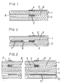
- FIG. 1 is a schematic, greatly enlarged illustration of a section through a sensor element according to the invention that can be produced in ceramic film and screen printing technology. It essentially consists of ceramic films 1 and 2, onto which the inner three-dimensional pump electrode 3 and the outer pump electrode are screened 4 and associated conductor tracks 5, 5 'have been printed on and which are laminated together by means of a customary interlaminar binder, forming the diffusion channel 6 forming a tunnel.
- the sensor element shown schematically in FIG. 2 differs from the sensor element shown in FIG. 1 only in that a porous filling 7 is provided in the diffusion channel 6, which serves as a diffusion barrier for the measuring gas.
- FIG. 3 is a further schematic, greatly enlarged illustration of a section through another advantageous embodiment of a sensor element according to the invention that can be produced in ceramic film and screen printing technology, in which the inner three-dimensional pump electrode 3 and the outer pump electrode 4 are arranged in a ring around the sample gas supply 8 . It essentially consists of four solid electrolyte foils 1, 2, 9 and 10 laminated together with the punched-out sample gas supply 8, the ring-shaped outer pump electrode 4 and the three-dimensional inner pump electrode 3 arranged in the diffusion channel 6.
- the sensor element also has a heater 11. The slides 9 and 10 with the heater are not absolutely necessary.
- the annular electrodes 3 and 4 are connected to conductor tracks 5 and 5 ', which are compared to the solid electrolyte foils by means of insulating layers, not shown in the drawing, for. B. Al2O3 layers are isolated.
- the conductor tracks are connected to a voltage source, not shown, for. B. a battery with a constant working voltage in the range of 0.5 to 1.0 volts.
- the outer pump electrode 4 and the associated conductor 5 ' are again with a porous cover layer, not shown, for. B. made of magnesium spinel covered.
- oxygen-ion-conducting solid electrolytes are in particular those based on ZrO2, HfO2, CeO2 and ThO2.
- YSZ zirconium dioxide
- the platelets and foils preferably have a thickness of 0.25 to 0.3 mm.
- the outer pump electrode 4 preferably consists of a metal from the platinum group, in particular platinum, or from alloys of metals from the platinum group or alloys from metals from the platinum group with other metals.
- the electrode can optionally also contain a ceramic scaffold material, as is also used to produce the inner pump electrode.
- the outer pump electrode 4 is, however, more of a two-dimensional two-dimensional electrode, ie an electrode of the usual type, which is generally thinner than the inner pump electrode and preferably has a thickness of 8 to 15 ⁇ m.
- the inner, three-dimensional pump electrode 3 preferably consists of a mixture of a metal of the platinum group, in particular platinum, or of an alloy, such as can also be used to produce the outer pump electrode, and a supporting framework material, such as, for. B. with Y2O3 stabilized zirconia.
- the metal of the platinum group can be wholly or partly by an electron-conducting metal or metal oxide, such as. B. TiO2 or Perovskite, or by a mixed conductive (ie electrode and ion conductive) metal oxide, such as. B. CeO2 or other rare earth oxides and mixed oxides such. B. uranium scandium oxides to be replaced.
- the volume fraction of scaffold material is expediently 20 to 60%, preferably 35 to 45%. It has also proven to be advantageous if the degree of porosity of the inner pump electrode is 10 to 40%. At least some of the pores preferably have a pore diameter of greater than 1 ⁇ m. The average pore diameter of the inner pump electrode is preferably 2 to 10 ⁇ m.
- the porous support structure can be produced by using known pore-forming powders, which are added to the mixture of metal component and support structure component and other customary additives used to produce the electrode, and are burned or evaporated during the manufacture of the sensor element. Typical pore formers that can be used successfully are z. B. theobromine and carbon black and carbonates.
- the pore size of the support structure can be controlled by the particle size of the pore former powder used.
- the use of pore formers is not absolutely necessary. Rather, it is also possible, for example, to produce a porous support structure by using a support structure material with comparatively low sintering activity.
- the masses used to produce the electrodes can be prepared by customary known methods and applied, preferably printed, onto the platelet-shaped or foil-shaped solid electrolytes.
- the inner three-dimensional pump electrode 3 is preferably directly opposite the outer pump electrode 4. It can cover the same, a smaller or larger area of the solid electrolyte than the outer pump electrode 4.
- the inner pump electrode 3 can accordingly only fill a comparatively small part of the diffusion channel 6 or a comparatively large part of the diffusion channel 6.
- the inner pump electrode 3 occupies only a part of the space of the diffusion channel 6 and a diffusion barrier 7 is arranged in the diffusion channel 6 in front of the inner pump electrode 3, as is shown schematically in FIG. 2, for example.
- Such a diffusion barrier consists of a porous material, i. H. a material that at the sintering temperature of the substrate, e.g. B. ZrO substrate, not yet dense, e.g. B. from coarse-grained ZrO2, Mg spinel or Al2O3 with a grain size of, for example, about 10 microns.
- pore formers can optionally be added, e.g. B. thermal carbon black that burns out during the sintering process, theobromine or ammonium carbonate.
- a channel system acting as a diffusion barrier for the measurement gas for a mixed diffusion of Knudsen and gas phase diffusion can be arranged in front of the inner pump electrode 3.
- This channel system can e.g. B. consist of porous filled diffusion channels for a Knudsen diffusion and hollow channels for a gas phase diffusion.
- Such channel systems acting as diffusion barriers for the measuring gas are described in more detail in DE-OS 37 28 289.
- the diffusion barrier can advantageously contain platinum or a platinum alloy or another catalytically active metal for the purpose of improving the measurement accuracy in order to achieve an equilibrium in the diffusion channel reaching gas.
- the volume fraction of catalytically active metal or metal alloy can be 10 to 90%.
- the diffusion barrier can occupy the entire space of the diffusion channel, which is left free by the inner pump electrode 3, or only part of the same. For example, a free space can also remain between the inner pump electrode 3 and the diffusion barrier 7.
- the diffusion barrier 7, like the inner pump electrode 3, can advantageously be produced using thick-film technology.
- the conductor tracks 5 and 5 'belonging to the pump electrodes 3 and 4 are preferably also made of platinum or a platinum alloy.
- Pump electrodes and conductor tracks can be applied to the solid electrolyte body by known methods, for example by screen printing. Between the outer pump electrode with a voltage source not shown in the drawing interconnect and the solid electrolyte carrier there is usually an insulation layer, for. B. from Al2O3. For example, it can have a thickness of approximately 15 ⁇ m.
- the inner conductor track is preferably insulated from solid electrolyte carriers in a similar manner.
- the union of the individual, the sensor element forming films or plates can be effected by means of a screen printing technique in the ceramic foil and usual method in which the film brought together and are heated to temperatures of about 100 ° C.
- the diffusion channel can be prepared at the same time. This is advantageously introduced using thick-film technology, for example through a theobromine screen printing layer, the theobromine being evaporated during the later sintering process. Thermal soot powders, for example, which burn out during the sintering process or ammonium carbonate, which evaporates, can also be used to produce the diffusion channel.
- the diffusion channel is to have a porous diffusion barrier
- a theobromine screen printing layer for example a layer of theobromine or another evaporable or combustible material and a material that does not yet sinter tightly at the applied sintering temperature of the solid electrolyte substrate, e.g. B. coarse-grained ZrO2, magnesium spinel or Al2O3 with a grain size of z. B. 10 microns can be used.
- films made of zirconium dioxide stabilized with yttrium and having a layer thickness of 0.3 mm were used.
- the outer pump electrode 4, which is made of platinum, and the inner platinum support frame electrode 3 were applied to the carrier foils using known screen printing technology, the surface of the carrier foil 1 carrying the outer puncture electrode 4 in the region of the conductor track 5 ′ of the outer pump electrode 4 being approximately 20 ⁇ m thick Al2O3 insulation layer was applied.
- the conductor track 5 was also insulated with appropriate insulation layers.
- the ring-shaped pump electrodes 3 and 4 had an outer diameter of 2.8 mm and an inner diameter of 1.4 mm with a thickness of the outer pump electrode of 12 ⁇ m and the inner pump electrode of 40 ⁇ m.
- the inner pump electrode was produced from a screen printing mass, which corresponded to the mass used to produce the outer pump electrode, with the difference that it contained such an amount of ZrO2 stabilized with Y2O3 that an electrode porosity degree of about 30% was achieved.
- the conductor tracks were produced from a conventional Pt cermet paste from 85 parts by weight of Pt powder and 15 parts by weight of YSZ powder.
- the diffusion channel 6 was placed in thick-film technology by a theobromine-screen-printed layer, wherein the theobromine during the subsequent sintering process in the temperature range of 300 o C under a Hinerarteries about 30 microns high and 1.3 mm deep annular gap was evaporated.
- the central sample gas feed opening had a diameter of 0.25 mm.
- the sensor elements produced were installed in the sensor housing of the type known from DE-OS 32 06 903 and 35 37 051 and used to measure the fuel-air ratio in lean and rich exhaust gases.
Landscapes
- Chemical & Material Sciences (AREA)
- Life Sciences & Earth Sciences (AREA)
- Health & Medical Sciences (AREA)
- Physics & Mathematics (AREA)
- Chemical Kinetics & Catalysis (AREA)
- Electrochemistry (AREA)
- Analytical Chemistry (AREA)
- Biochemistry (AREA)
- General Health & Medical Sciences (AREA)
- General Physics & Mathematics (AREA)
- Immunology (AREA)
- Pathology (AREA)
- Molecular Biology (AREA)
- Measuring Oxygen Concentration In Cells (AREA)
- Investigating Or Analyzing Materials By The Use Of Fluid Adsorption Or Reactions (AREA)
Abstract
Description
Die Erfindung geht aus von einem Sensorelement für Grenzstromsensoren nach der Gattung des Hauptanspruchs. Bei derartigen Sensorelementen, die nach dem Diffusionsgrenzstromprinzip arbeiten, wird der Diffusionsgrenzstrom bei einer konstanten, an den beiden Elektroden des Sensorelementes anliegenden Spannung gemessen. Dieser Strom ist in einem bei Verbrennungsvorgängen entstehenden Abgas von der Sauerstoffkonzentration solange abhängig, wie die Diffusion des Gases zur Pumpelektrode die Geschwindigkeit der ablaufenden Reaktion bestimmt. Es ist bekannt, derartige, nach dem polarographischen Meßprinzip arbeitende Sensoren in der Weise aufzubauen, daß sowohl Anode als auch Kathode dem zu messenden Gas ausgesetzt sind, wobei die Kathode eine Diffusionsbarriere aufweist, um ein Arbeiten im Diffusionsgrenzstrombereich zu erzielen.The invention is based on a sensor element for limit current sensors according to the preamble of the main claim. In sensor elements of this type which operate according to the diffusion limit current principle, the diffusion limit current is measured at a constant voltage applied to the two electrodes of the sensor element. This current is dependent on the oxygen concentration in an exhaust gas generated during combustion processes, as long as the diffusion of the gas to the pump electrode determines the speed of the reaction taking place. It is known to construct such sensors, which operate according to the polarographic measuring principle, in such a way that both the anode and the cathode are exposed to the gas to be measured, the cathode having a diffusion barrier in order to achieve work in the diffusion limit current range.
Die bekannten Grenzstromsensoren dienen in der Regel zur Bestimmung des λ-Wertes von Gasgemischen, der das Verhältnis "Gesamtsauerstoff/zur vollständigen Verbrennung des Kraftstoffs benötigten Sauerstoff" des in einem Zylinder verbrennenden Luft/Kraftstoffgemisches bezeichnet, wobei die Sensoren den Sauerstoffgehalt des Abgases über eine elektrochemische Pumpstrommessung ermitteln.The known limit current sensors are generally used to determine the λ value of gas mixtures, which denotes the ratio "total oxygen / oxygen required for complete combustion of the fuel" of the air / fuel mixture burning in a cylinder, the sensors determining the oxygen content of the exhaust gas via an electrochemical Determine pump current measurement.
Aufgrund einer vereinfachten und kostengünstigen Herstellungsweise hat sich in der Praxis in den letzten Jahren die Herstellung von in Keramikfolien- und Siebdrucktechnik herstellbaren Sensorelementen durchgesetzt.Due to a simplified and inexpensive production method, the production of sensor elements that can be produced using ceramic film and screen printing technology has become established in practice in recent years.
In einfacher und rationeller Weise lassen sich planare Sensorelemente ausgehend von plättchen- oder folienförmigen sauerstoffleitenden Festeleketrolyten, z.B. aus stabilisiertem Zirkondioxid, herstellen, die beidseitig mit je einer inneren und äußeren Pumpelektrode mit dazugehörigen Leiterbahnen beschichtet werden. Die innere Pumpelektrode befindet sich dabei in vorteilhafter Weise im Randbereich eines Diffusionskanals, durch den das Meßgas zugeführt wird, und der als Gasdiffusionswiderstand dient.In a simple and efficient manner, planar sensor elements can be started from platelet-shaped or foil-shaped oxygen-conducting solid electrolytes, e.g. Made of stabilized zirconia, which are coated on both sides with an inner and outer pump electrode with associated conductor tracks. The inner pump electrode is advantageously located in the edge region of a diffusion channel through which the measurement gas is supplied and which serves as a gas diffusion resistor.
Aus der DE-OS 35 43 759 sowie den EP-A 0 142 993, 0 188 900 und 0 194 082 sind ferner Sensorelemente und Detektoren bekannt, denen gemein ist, daß sie jeweils eine Pumpzelle und eine Sensorzelle aufweisen, die aus plättchen- oder folienförmigen sauerstoffleitenden Festelektrolyten und zwei hierauf angeordneten Elektroden bestehen und einen gemeinsamen Diffusionskanal aufweisen.From DE-OS 35 43 759 and EP-A 0 142 993, 0 188 900 and 0 194 082 sensor elements and detectors are also known, which have in common that they each have a pump cell and a sensor cell made of platelet or consist of film-shaped oxygen-conducting solid electrolytes and two electrodes arranged thereon and have a common diffusion channel.
Der aus der DE-OS 35 43 759 bekannte, in Planartechnik aufgebaute Breitbandsensor, weist eine Pumpzelle und eine parallel dazu angeordnete Konzentrationszelle auf, die einen dazwischenliegenden Diffusionskanal begrenzen. Für die Elektroden werden Schichtdicken von etwa 20 µm angegeben, gegenüber etwa 0,1 mm für den Diffusionskanal. Die Elektroden, somit auch die innere Pumpelektrode, sind also dünn im Vergleich zum Diffusionskanal.The broadband sensor, known from DE-OS 35 43 759 and constructed using planar technology, has a pump cell and a concentration cell arranged parallel thereto, which delimit an intermediate diffusion channel. Layer thicknesses of about 20 µm are given for the electrodes, compared to about 0.1 mm for the diffusion channel. The electrodes, and thus the inner pump electrode, are therefore thin in comparison to the diffusion channel.
Der beschriebene Breitbandsensor funktioniert in bekannter Weise, indem der durch die Pumpzelle fließende Strom so geregelt wird, daß die Spannung über der Konzentrationszelle konstant ist. Der über die Pumpzelle fließende Strom liefert das Ausgangssignal.The broadband sensor described functions in a known manner by regulating the current flowing through the pump cell so that the voltage across the concentration cell is constant. The current flowing through the pump cell provides the output signal.
Die EP-A 0 141 993 beschreibt mehrere Varianten von Planarsonden zur Sauerstoffmessung, darunter auch eine Ausführungsform mit Pumpzelle und Konzentrationszelle, wobei jeweils eine innere Elektrode der Pumpzelle und eine Elektrode der Konzentrationszelle in einem Diffusionskanal für das Meßgas angeordnet sind. Wie aus den Abbildungen ersichtlich ist jedoch die Elektrodenschichtdicke klein im Vergleich zur Höhe des Diffusionskanals.EP-A 0 141 993 describes several variants of planar probes for oxygen measurement, including an embodiment with a pump cell and concentration cell, an inner electrode of the pump cell and an electrode of the concentration cell being arranged in a diffusion channel for the measurement gas. However, as can be seen from the figures, the electrode layer thickness is small compared to the height of the diffusion channel.
Nachteilig an Sensorelementen nach der Gattung des Hauptanspruchs ist, daß der vordere, dem zugeführten Meßgas zugewandte Teil der inneren Pumpelektrode stärker als der hintere, dem zugeführten Meßgas abgewandte Teil der Pumpelektrode beansprucht wird. Dies führt zu einer hohen Elektrodenpolarisation, die eine hohe Pumpspannung erfordert. Letztere wiederum birgt die Gefahr einer Elektrolytzersetzung im Bereich der inneren Pumpelektrode in sich.A disadvantage of sensor elements according to the preamble of the main claim is that the front part of the inner pump electrode facing the supplied measuring gas is subjected to greater stress than the rear part of the pump electrode facing away from the measuring gas supplied. This leads to a high electrode polarization, which requires a high pump voltage. The latter in turn harbors the risk of electrolyte decomposition in the area of the inner pump electrode.
In der DE-A 37 28 618 veröffentlicht aus 4.8.88 wird daher vorgeschlagen, in einem Sensorelement für Grenzstromsensoren zur Bestimmung des λ-Wertes von Gasgemischen mit auf einem 0²⁻-Ionen leitenden plättchen- oder folienförmigen Festelektrolyten angeordneten äußeren und inneren Pumpelektroden, von denen die innere Pumpelektrode auf dem plättchen- oder folienförmigen Festelektrolyten in einem Diffusionskanal für das Meßgas angeordnet ist, sowie mit Leiterbahnen für die Pumpelektroden, in dem Diffusionskanal auf der der inneren Pumpelektrode gegenüberliegenden Seite mindestens eine zweite innere Pumpelektrode anzuordnen, die mit der ersten inneren Pumpelektrode kurzgeschlossen ist.In DE-A 37 28 618 published from 4.8.88 it is therefore proposed to use a sensor element for limit current sensors to determine the λ value of gas mixtures with outer and inner solid electrolytes arranged on a platelet or film-shaped solid electrolyte that conduct 0²⁻ ions Pump electrodes, of which the inner pump electrode is arranged on the platelet-shaped or film-shaped solid electrolyte in a diffusion channel for the measuring gas, and with conductor tracks for the pump electrodes, in the diffusion channel on the side opposite the inner pump electrode to arrange at least one second inner pump electrode which is connected to the first inner pump electrode is short-circuited.
Das erfindungsgemäße Sensorelement mit den kennzeichnenden Merkmalen des Hauptanspruchs hat demgegenüber den Vorteil, daß durch die besondere Ausgestaltung der inneren Pumpelektrode infolge ihrer größeren Elektrodenfläche ihre Belastbarkeit erhöht und die Lebensdauer des Sensorelementes verbessert wird. Ein weiterer Vorteil ergibt sich daraus, daß die innere Pumpelektrode bei der Herstellung des Sensorelementes in Keramikfolien- und Siebdrucktechnik beim Laminieren und Pressen eine Stützfunktion übernimmt.The sensor element according to the invention with the characterizing features of the main claim has the advantage that the resilience is increased by the special design of the inner pump electrode due to its larger electrode area and the life of the sensor element is improved. Another advantage results from the fact that the inner pump electrode assumes a supporting function in the production of the sensor element in ceramic foil and screen printing technology during lamination and pressing.
Das erfindungsgemäße Sensorelement läßt sich anstelle bekannter Sensorelemente planarer Struktur in Grenzstromsensoren üblicher Bauart verwenden. In Frage kommen dabei Breitbandsensoren (λ ≷ 1) und Magersensoren (λ > 1). Das erfindungsgemäße Sensorelement kann somit allein als Pumpzelle gegebenenfalls mit einem Heizelement, ausgebildet sein, z. B. als Magersensor für Dieselmotoren, und als solches in ein übliches Sensorgehäuse, z. B. des aus den DE-OS 32 06 903 und 35 37 051 bekannten Typs eingebaut und zur Messung des Kraftstoff-Luft-Verhältnisses in einem mageren Abgas verwendet werden. Das erfindungsgemäße Sensorelement kann jedoch auch außer der Pumpzelle zusätzlich noch eine Sensorzelle (Nernstzelle) aufweisen, die mit einem zusätzlichen Luftreferenzkanal versehen ist und deren eine Elektrode im Bereich der Pumpelektrode im Diffusionskanal der Pumpzelle angeordnet ist und deren andere Elektrode sich im Luftreferenzkanal befindet und zur Messung des Kraftstoff-Luft-Verhältnisses in einem mageren oder fetten Abgas verwendet werden.The sensor element according to the invention can be used in place of known sensor elements with a planar structure in limit current sensors of conventional design. Broadband sensors (λ ≷ 1) and lean sensors (λ> 1) come into question. The sensor element according to the invention can thus be designed as a pump cell, optionally with a heating element, for. B. as a lean sensor for diesel engines, and as such in a conventional sensor housing, for. B. of the type known from DE-OS 32 06 903 and 35 37 051 installed and used to measure the air-fuel ratio in a lean exhaust gas. However, in addition to the pump cell, the sensor element according to the invention can also additionally have a sensor cell (Nernst cell) which is provided with an additional air reference channel and whose one electrode is arranged in the region of the pump electrode in the diffusion channel of the pump cell and whose other electrode is located in the air reference channel and for measurement of the air-fuel ratio be used in a lean or rich exhaust gas.
In der Zeichnung sind vorteilhafte Ausführungsformen erfindungsgemäßer Sensorelemente dargestellt.Advantageous embodiments of sensor elements according to the invention are shown in the drawing.
Fig. 1 ist eine schematische, stark vergrößerte Darstellung eines Schnitts durch ein in Keramikfolien- und Siebdrucktechnik herstellbares Sensorelement nach der Erfindung, Es besteht im wesentlichen aus den Keramikfolien 1 und 2, auf die nach dem Siebdruckverfahren die innere dreidimensionale Pumpelektrode 3 sowie die äußere Pumpelektrode 4 nebst dazugehörigen Leiterbahnen 5, 5' aufgedruckt worden sind und die unter Ausbildung des einen Tunnel bildenden Diffusionskanals 6 mittels eines üblichen interlaminaren Binders zusammenlaminiert sind. In vorteilhafter Weise sind die äußere Pumpelektrode 4 und die dazugehörige Leiterbahn 5' mit einer nicht dargestellten porösen Deckschicht, z. B. aus Mg-Spinell, abgedeckt.1 is a schematic, greatly enlarged illustration of a section through a sensor element according to the invention that can be produced in ceramic film and screen printing technology. It essentially consists of
Das in Fig. 2 schematisch dargestellte Sensorelement unterscheidet sich von dem in Fig. 1 dargestellten Sensorelement lediglich dadurch, daß in dem Diffusionskanal 6 eine poröse Füllung 7 vorgesehen ist, die als Diffusionsbarriere für das Meßgas dient.The sensor element shown schematically in FIG. 2 differs from the sensor element shown in FIG. 1 only in that a porous filling 7 is provided in the
Fig. 3 ist eine weitere schematische, stark vergrößerte Darstellung eines Schnitts durch eine andere in Keramikfolien- und Siebdrucktechnik herstellbare, vorteilhafte Ausführungsform eines Sensorelementes nach der Erfindung, bei dem die innere dreidimensionale Pumpelektrode 3 sowie die äußere Pumpelektrode 4 ringförmig um die Meßgaszuführung 8 angeordnet sind. Es besteht im wesentlichen aus vier zusammenlaminierten Festelektrolytfolien 1, 2, 9 und 10 mit der ausgestanzten Meßgaszuführung 8, der ringförmigen äußeren Pumpelektrode 4 und der dreidimensionalen, im Diffusionskanal 6 angeordneten inneren Pumpelektrode 3. Im Falle der in Fig. 3 dargestellten Ausführungsform weist das Sensorelement ferner einen Heizer 11 auf. Die Folien 9 und 10 mit den Heizer sind jedoch nicht zwingend erforderlich. Die ringförmigen Elektroden 3 und 4 sind an Leiterbahnen 5 und 5' angeschlossen, die gegenüber den Festelektrolytfolien mittels in der Zeichnung nicht dargestellter Isolierschichten, z. B. Al₂O₃-Schichten, isoliert sind. Die Leiterbahnen sind an eine nicht dargestellte Spannungsquelle angeschlossen, z. B. eine Batterie mit einer konstanten Arbeitsspannung im Bereich von 0,5 bis 1,0 Volt. In vorteilhafter Weise sind die äußere Pumpelektrode 4 und die dazugehörige Leiterbahn 5' wiederum mit einer nicht dargestellten porösen Deckschicht, z. B. aus Magnesium-Spinell, abgedeckt.3 is a further schematic, greatly enlarged illustration of a section through another advantageous embodiment of a sensor element according to the invention that can be produced in ceramic film and screen printing technology, in which the inner three-
Zur Herstellung erfindungsgemäßer Sensorelemente geeignete sauerstoffionenleitende Festelektrolyte sind insbesondere solche auf Basis von ZrO₂, HfO₂, CeO₂ und ThO₂. Als besonders vorteilhaft hat sich die Verwendung von Plättchen und Folien aus mit Yttrium stabilisiertem Zirkoniumdioxid (YSZ) erwiesen.Suitable for the production of sensor elements according to the invention oxygen-ion-conducting solid electrolytes are in particular those based on ZrO₂, HfO₂, CeO₂ and ThO₂. The use of platelets and foils made of zirconium dioxide (YSZ) stabilized with yttrium has proven to be particularly advantageous.
Die Plättchen und Folien haben dabei vorzugsweise eine Dicke von 0,25 bis 0,3 mm.The platelets and foils preferably have a thickness of 0.25 to 0.3 mm.
Die äußere Pumpelektrode 4 besteht vorzugsweise aus einem Metall der Platingruupe, insbesondere Platin, oder aus Legierungen von Metallen der Platingruppe oder Legierungen von Metallen der Platingruppe mit anderen Metallen. Die Elektrode kann gegebenenfalls auch ein keramisches Stützgerüstmaterial, wie es auch zur Erzeugung der inneren Pumpelektrode verwendet wird, enthalten. Im Gegensatz zu der hier als "dreidimensional" bezeichneten inneren Pumpelektrode 3 stellt die äußere Pumpelektrode 4 jedoch eher eine mehr flächige zweidimensionale Elektrode, d. h. eine Elektrode üblichen Typs dar, die in der Regel dünner als die innere Pumpelektrode ist und vorzugsweise eine Dicke von 8 bis 15 µm aufweist.The
Die innere, dreidimensionale Pumpelektrode 3 besteht vorzugsweise aus einer Mischung aus einem Metall der Platingruppe, insbesondere Platin, oder aus einer Legierung, wie sie auch zur Erzeugung der äußeren Pumpelektrode verwendet werden kann, und einem Stützgerüstmaterial, wie z. B. mit Y₂O₃ stabilisiertem Zirkondioxid. Gegebenenfalls kann das Metall der Platingruppe ganz oder teilweise durch ein elektronenleitendes Metall bzw. Metalloxid, wie z. B. TiO₂ oder Perovskite, oder durch ein gemischtleitendes (d. h. elektroden- und ionenleitendes)Metalloxid, wie z. B. CeO₂ oder andere Oxide der seltenen Erden sowie Mischoxide wie z. B. Uran-Scandium-Oxide, ersetzt werden. Der Volumenanteil an Stützgerüstmaterial liegt zweckmäßig bei 20 bis 60 %, vorzugsweise bei 35 bis 45 %. Als vorteilhaft hat es sich ferner erwiesen, wenn der Porositätsgrad der inneren Pumpelektrode bei 10 bis 40 % liegt. Mindestens ein Teil der Poren weist dabei vorzugsweise einen Porendurchmesser von größer als 1 µm auf. Der mittlere Porendurchmesser der inneren Pumpelektrode liegt dabei vorzugsweise bei 2 bis 10 µm. Das poröse Stützgerüst läßt sich dabei durch Einsatz bekannter Porenbildnerpulver erzeugen, die der zur Erzeugung der Elektrode verwendeten Mischung aus Metallkomponente und Stützgerüstkomponente sowie anderen üblichen Zusätzen zugesetzt werden und bei der Herstellung des Sensorelementes verbrannt oder verdampft werden.Typische Porenbildner, die mit Erfolg eingesetzt werden können, sind z. B. Theobromin und Ruß sowie Carbonate. Die Porengröße des Stützgerüstes läßt sich dabei durch die Teilchengröße des eingesetzten Porenbildnerpulvers steuern. Die Verwendnung von Porenbildnern ist jedoch nicht unbedingt erforderlich Vielmehr ist es beispielsweise auch möglich, ein poröses Stützgerüst durch Verwendung eines Stützgerüstmaterials mit vergleichsweise geringer Sinteraktivität zu erzeugen. Die zur Erzeugung der Elektroden verwendeten Massen lassen sich nach üblichen bekannten Methoden zubereiten und auf die plättchen- oder folienförmigen Festelektrolyten aufbringen, vorzugsweise aufdrucken.The inner, three-
Die innere dreidimensionale Pumpelektrode 3 liegt der äußeren Pumpelektrode 4 vorzugsweise direkt gegenüber. Sie kann die gleiche, eine kleinere oder größere Fläche des Festelektrolyten bedecken als die äußere Pumpelektrode 4. Die innere Pumpelektrode 3 kann dementsprechend nur einen vergleichsweise kleinen Teil des Diffusionskanals 6 oder einen vergleichsweise großen Teil des Diffusionskanals 6 ausfüllen.The inner three-
Gemäß einer besonders vorteilhaften Ausgestaltung der Erfindung nimmt die innere Pumpelektrode 3 nur einen Teil des Raumes des Diffusionskanals 6 ein und im Diffusionskanal 6 ist vor der inneren Pumpelektrode 3 eine Diffusionsbarriere 7 angeordnet, wie es beispielsweise in Fig. 2 schematisch dargestellt ist.According to a particularly advantageous embodiment of the invention, the
Eine solche Diffusionsbarriere besteht aus einem porösen Material, d. h. einem Material, das bei der Sintertemperatur des Substrates, z. B. ZrO-Substrates, noch nicht dicht sintert, z. B. aus grobkörnigem ZrO₂, Mg-Spinell oder Al₂O₃ mit einer Korngröße von beispielsweise etwa 10 µm. Zur Ausbildung einer ausreichenden Porosität können gegebenenfalls Porenbildner zugesetzt werden, z. B. Thermalrußpulver, das beim Sinterprozeß ausbrennt, Theobromin oder Ammoniumcarbonat. Gemäß einer besonders vorteilhaften Ausgestaltung der Erfindung kann vor der inneren Pumpelektrode 3 ein als Diffusionsbarriere für das Meßgas wirkendes Kanalsystem für eine Mischdiffusion aus Knudsen- und Gasphasendiffusion angeordnet sein. Dieses Kanalsystem kann z. B. aus porös gefüllten Diffusionskanälen für eine Knudsendiffusion und hohlen Kanälen für eine Gasphasendiffusion bestehen. Derartige als Diffusionsbarrieren für das Meßgas wirkende Kanalsysteme werden näher in der DE-OS 37 28 289 beschrieben.Such a diffusion barrier consists of a porous material, i. H. a material that at the sintering temperature of the substrate, e.g. B. ZrO substrate, not yet dense, e.g. B. from coarse-grained ZrO₂, Mg spinel or Al₂O₃ with a grain size of, for example, about 10 microns. To form a sufficient porosity, pore formers can optionally be added, e.g. B. thermal carbon black that burns out during the sintering process, theobromine or ammonium carbonate. According to a particularly advantageous embodiment of the invention, a channel system acting as a diffusion barrier for the measurement gas for a mixed diffusion of Knudsen and gas phase diffusion can be arranged in front of the
In vorteilhafter Weise kann die Diffusionsbarriere zum Zwecke der Verbesserung der Meßgenauigkeit Platin oder eine Platinlegierung oder ein anderes katalytisch wirkendes Metall enthalten, um eine Gleichgewichtseinstellung des in den Diffusionskanal gelangenden Gases zu erreichen. Der Volumenanteil an katalytisch wirkendem Metall oder Metallegierung kann bei 10 bis 90 % liegen. Die Diffusionsbarriere kann den gesamten, von der inneren Pumpelektrode 3 freigelassenen Raum des Diffusionskanals einnehmen oder nur einen Teil desselben. So kann beispielsweise auch zwischen der inneren Pumpelektrode 3 und der Diffusionsbarriere 7 ein freier Raum verbleiben. Die Diffusionsbarriere 7 läßt sich wie die innere Pumpelektrode 3 in vorteilhafter Weise in Dickschichttechnik erzeugen.The diffusion barrier can advantageously contain platinum or a platinum alloy or another catalytically active metal for the purpose of improving the measurement accuracy in order to achieve an equilibrium in the diffusion channel reaching gas. The volume fraction of catalytically active metal or metal alloy can be 10 to 90%. The diffusion barrier can occupy the entire space of the diffusion channel, which is left free by the
Die zu den Pumpelektroden 3 und 4 gehörenden Leiterbahnen 5 und 5' bestehen vorzugsweise ebenfalls aus Platin oder einer Platinlegierung. Pumpelektroden und Leiterbahnen können mittels bekannter Verfahren auf den Festelektrolytkörper aufgebracht werden, beispielsweise durch Siebdrucken. Zwischen der die äußere Pumpelektrode mit einer in der Zeichnung nicht dargestellten Spannungsquelle verbindenden Leiterbahn und dem Festelektrolytträger befindet sich in der Regel eine Isolationsschicht, z. B. aus Al₂O₃. Sie kann beispielsweise eine Stärke von etwa 15 µm haben. Vorzugsweise ist die innere Leiterbahn auf ähnliche Weise von Festelektrolytträger isoliert. Die Vereinigung der einzelnen, das Sensorelement bildenden Folien oder Plättchen kann mittels eines in der Keramikfolien- und Siebdrucktechnik üblichen Verfahrens erfolgen, bei dem die Folien zusammengeführt und auf Temperaturen von etwa 100 oC erhitzt werden. Dabei kann gleichzeitig der Diffusionskanal vorbereitet werden. In vorteilhafter Weise wird dieser in Dickschichttechnik eingebracht, beispielsweise durch eine Theobrominsiebdruckschicht, wobei das Theobromin beim späteren Sinterprozeß verdampft wird. Zur Erzeugung des Diffusionskanals ebenfalls verwendbar sind beispielsweise Thermalrußpulver, die beim Sinterprozeß ausbrennen oder Ammoniumcarbonat, das verdampft.The conductor tracks 5 and 5 'belonging to the
Soll der Diffusionskanal eine poröse Diffusionsbarriere aufweisen, so kann beispielsweise anstelle einer Theobrominsiebdruckschicht eine Schicht aus Theobromin oder einem anderen verdampf- oder verbrennbaren Material und einem Material, das bei der angewandten Sintertemperatur des Festelektrolytsubstrates noch nicht dicht sintert, z. B. grobkörniges ZrO₂, Magnesiumspinell oder Al₂O₃ mit einer Korngröße von z. B. 10 µm verwendet werden.If the diffusion channel is to have a porous diffusion barrier, then instead of a theobromine screen printing layer, for example a layer of theobromine or another evaporable or combustible material and a material that does not yet sinter tightly at the applied sintering temperature of the solid electrolyte substrate, e.g. B. coarse-grained ZrO₂, magnesium spinel or Al₂O₃ with a grain size of z. B. 10 microns can be used.
Zur Herstellung eines Sensorelementes des in Fig. 3 schematisch dargestellten Typs wurden Folien aus mit Yttrium stabilisiertem Zirkondioxid einer Schichtstärke von 0,3 mm verwendet. Das Aufbringen der aus Platin bestehenden äußeren Pumpelektrode 4 und der inneren Platin-Stützgerüstelektrode 3 auf die Trägerfolien erfolgte in bekannter Siebdrucktechnik, wobei auf die die äußere Punpelektrode 4 tragende Oberfläche der Trägerfolie 1 im Bereich der Leiterbahn 5' der äußeren Pumpelektrode 4 zuvor eine etwa 20 µm dicke Al₂O₃-Isolationsschicht aufgetragen wurde. Mit entsprechenden Isolationsschichten wurde ferner die Leiterbahn 5 isoliert. Die ringförmigen Pumpelektroden 3 und 4 hatten einen Außendurchmesser von 2,8 mm und einen Innendurchmesser von 1,4 mm bei einer Dicke der äußeren Pumpelektrode von 12 µm und der inneren Pumpelektrode von 40 µm. Die innere Pumpelektrode wurde ausgehend von einer Siebdruckmasse erzeugt, die der zur Erzeugung der äußeren Pumpelektrode verwendeten Masse entsprach mit dem Unterschied, daß sie eine solche Menge an mit Y₂O₃ stabilisiertem ZrO₂ enthielt, daß ein Elektroden-Porositätsgrad von etwa 30 % erzielt wurde. Die Leiterbahnen wurden ausgehend von einer üblichen Pt-Cermetpaste aus 85 Gew.-Teilen Pt-Pulver und 15 Gew.-Teilen YSZ-Pulver erzeugt. Der Diffusionskanal 6 wurde in Dickschichttechnik durch eine Theobromin-Siebdruckschicht eingebracht, wobei das Theobromin beim späteren Sinterprozeß im Temperaturbereich um 300 oC unter Hinerlassen eines etwa 30 µm hohen und 1,3 mm tiefen Ringspaltes verdampft wurde. Die zentrale Meßgaszufuhröffnung hatte einen Durchmesser von 0,25 mm. Nach dem Bedrucken der Trägerfolien, d. h. nach Aufbringen der Elektroden, Leiterbahnen, Isolierschichten sowie gegebenenfalls einer Deckschicht auf die äußere Pumpelektrode wurden die Folien nach Zusammenfügen einem Sinterprozeß unterworfen, bei dem sie etwa 3 Stunden lang auf eine Temperatur im Bereich von 1380 oC erhitzt wurden.For the production of a sensor element of the type shown schematically in FIG. 3, films made of zirconium dioxide stabilized with yttrium and having a layer thickness of 0.3 mm were used. The
Zur Herstellung eines weiteren Sensorelementes mit einem Heizer, wie in Fig. 3 schematisch dargestellt, wurden vor dem Erhitzen weitere Folien mit einem aufgedruckten Heizer zulaminiert.To produce a further sensor element with a heater, as shown schematically in FIG. 3, further foils were laminated with a printed heater before heating.
Die hergestellten Sensorelemente wurden im Sensorgehäuse des aus den DE-OS 32 06 903 und 35 37 051 bekannten Typs eingebaut und zur Messung des Kraftstoff-Luft-Verhältnisses in mageren und fetten Abgasen verwendet.The sensor elements produced were installed in the sensor housing of the type known from DE-OS 32 06 903 and 35 37 051 and used to measure the fuel-air ratio in lean and rich exhaust gases.
Claims (11)
- Sensor element for limiting current sensors for determining the lambda value of gas mixtures, in particular of exhaust gases of internal-combustion engines, which sensor element has on a solid electrolyte (1) conducting O²⁻ ions and in platelet or sheet form at least one outer pumping electrode (4) and at least one inner pumping electrode (3), of which the inner pumping electrode (3) is arranged on the solid electrolyte (1) in platelet or sheet form in a diffusion channel (6) for the gas to be measured, as well as conductor tracks (5, 5') for the pumping electrodes, characterised in that the inner pumping electrode (3), arranged in the diffusion channel (6), comprises a three-dimensional, porous electrode of precious metal and/or metal oxide, having a supporting framework and with a thickness corresponding to the height of the diffusion channel (6).
- Sensor element according to Claim 1, characterised in that the height of the diffusion channel, and consequently the thickness of the inner pumping electrode, is 30 to 100 µm.
- Sensor element according to Claim 1, characterised in that the inner pumping electrode (3) comprises a three-dimensional platinum electrode having a supporting framework.
- Sensor element according to Claim 3, characterised in that the platinum in the electrode is substituted completely or partially by an electron-conducting metal or metal oxide and/or by a mixed-conducting (i.e electron- and ion-conducting) metal or metal oxide.
- Sensor element according to one of Claims 1 to 4, characterised in that the inner pumping electrode has a degree of porosity of 10 to 40%.
- Sensor element according to one of Claims 1 to 5, characterised in that the average pore diameter of the inner pumping electrode is around 2 to 10 µm.
- Sensor element according to one of Claims 1 to 6, characterised in that a porous diffusion barrier (7) is arranged ahead of the inner three-dimensional pumping electrode (3) arranged in the diffusion channel (6).
- Sensor element according to Claim 7, characterised in that, for equilibrium adjustment of the gas mixture passing into the diffusion channel, the porous diffusion barrier (7) contains a precious metal, in particular platinum.
- Sensor element according to one of Claims 1 to 8, characterised in that the sensor element is produced by the ceramic-sheet and screen-printing technique.
- Sensor element according to one of Claims 1 to 9, characterised in that the outer pumping electrode (4) and the inner pumping electrode (3) are arranged annularly around the feed (8) for the gas to be measured.
- Sensor element according to Claims 7 and 8, characterised in that the diffusion barrier (7) has a system of channels for a mixed diffusion of Knudsen and gas-phase diffusion.
Applications Claiming Priority (2)
| Application Number | Priority Date | Filing Date | Title |
|---|---|---|---|
| DE3809154A DE3809154C1 (en) | 1988-03-18 | 1988-03-18 | |
| DE3809154 | 1988-03-18 |
Publications (2)
| Publication Number | Publication Date |
|---|---|
| EP0406252A1 EP0406252A1 (en) | 1991-01-09 |
| EP0406252B1 true EP0406252B1 (en) | 1993-05-05 |
Family
ID=6350114
Family Applications (1)
| Application Number | Title | Priority Date | Filing Date |
|---|---|---|---|
| EP89902373A Expired - Lifetime EP0406252B1 (en) | 1988-03-18 | 1989-02-23 | ELEMENT FOR LIMIT-CURRENT SENSORS FOR DETERMINING THE $g(l) VALUE OF A GAS MIXTURE |
Country Status (8)
| Country | Link |
|---|---|
| US (1) | US5137615A (en) |
| EP (1) | EP0406252B1 (en) |
| JP (1) | JP2654212B2 (en) |
| KR (1) | KR0148683B1 (en) |
| AU (1) | AU613453B2 (en) |
| DE (2) | DE3809154C1 (en) |
| ES (1) | ES2010896A6 (en) |
| WO (1) | WO1989008840A1 (en) |
Cited By (1)
| Publication number | Priority date | Publication date | Assignee | Title |
|---|---|---|---|---|
| DE102010012889B4 (en) * | 2009-03-27 | 2021-05-06 | Ngk Spark Plug Co., Ltd. | Gas sensor |
Families Citing this family (34)
| Publication number | Priority date | Publication date | Assignee | Title |
|---|---|---|---|---|
| DE3841611A1 (en) * | 1988-12-10 | 1990-06-13 | Bosch Gmbh Robert | SENSOR ELEMENT FOR LIMIT CURRENT SENSORS FOR DETERMINING THE (LAMBDA) VALUE OF GAS MIXTURES |
| DE3908393A1 (en) * | 1989-03-15 | 1990-09-27 | Bosch Gmbh Robert | SENSOR ELEMENT FOR LIMIT CURRENT SENSORS FOR DETERMINING THE (LAMBDA) VALUE OF GAS MIXTURES |
| DE3941837C2 (en) * | 1989-12-19 | 1994-01-13 | Bosch Gmbh Robert | Resistance sensor for detecting the oxygen content in gas mixtures and process for its production |
| DE4032436A1 (en) * | 1990-10-12 | 1992-04-16 | Bosch Gmbh Robert | SENSOR ELEMENT FOR LIMIT CURRENT SENSORS FOR DETERMINING THE (GAMMA) VALUE OF GAS MIXTURES |
| DE4231966A1 (en) * | 1992-09-24 | 1994-03-31 | Bosch Gmbh Robert | Planar polarographic probe for determining the lambda value of gas mixtures |
| DE4238688A1 (en) * | 1992-11-17 | 1994-05-19 | Bosch Gmbh Robert | Sintered solid electrolyte with high oxygen ion conductivity |
| JP3314426B2 (en) * | 1992-12-25 | 2002-08-12 | 株式会社デンソー | Oxygen sensor |
| CA2262755A1 (en) * | 1996-04-30 | 1997-11-06 | Fernando H. Garzon | Solid-state gas sensor |
| WO1998020334A1 (en) * | 1996-11-06 | 1998-05-14 | Robert Bosch Gmbh | Electrochemical sensor |
| US5887240A (en) * | 1998-05-11 | 1999-03-23 | General Motors Corporation | Method of manufacturing a platinum electrode |
| DE19834276A1 (en) * | 1998-07-30 | 2000-02-10 | Bosch Gmbh Robert | Flue gas probe |
| DE19857471A1 (en) * | 1998-12-14 | 2000-06-15 | Bosch Gmbh Robert | Solid electrolyte lambda sensor for exhaust gases includes diffusion barrier set back from inner wall of gas entry hole, and chambers formed by cores vaporized during sintering process |
| DE10020082B4 (en) * | 2000-04-22 | 2012-04-05 | Robert Bosch Gmbh | Electrochemical sensor |
| DE10033906A1 (en) | 2000-07-12 | 2002-02-28 | Bosch Gmbh Robert | Platinum metal-containing ceramite electrodes for the electrochemical reduction of oxygen |
| DE10121889C2 (en) * | 2001-05-05 | 2003-07-24 | Bosch Gmbh Robert | sensor element |
| DE10122271B4 (en) * | 2001-05-08 | 2006-06-29 | Robert Bosch Gmbh | sensor elements |
| DE10146545A1 (en) * | 2001-09-21 | 2003-04-10 | Merck Patent Gmbh | microcomponent |
| JP4416551B2 (en) * | 2004-03-29 | 2010-02-17 | 日本碍子株式会社 | Porous electrode, electrochemical cell using the same, and NOx sensor element |
| EP1605255A1 (en) * | 2004-06-10 | 2005-12-14 | Hitachi, Ltd. | Oxygen-concentration detecting element and method of producing same |
| DE102005006501A1 (en) * | 2005-02-14 | 2006-08-24 | Robert Bosch Gmbh | Gas sensor |
| DE102005052430A1 (en) * | 2005-11-03 | 2007-05-10 | Robert Bosch Gmbh | sensor element |
| US20070245803A1 (en) * | 2006-02-23 | 2007-10-25 | Tan Siong S | Oxygen sensor with a protective layer |
| DE102007049713A1 (en) | 2006-12-29 | 2008-07-03 | Robert Bosch Gmbh | Sensor element for use in lambda oxygen sensor of motor vehicle, has electrode separated from gas chamber by partition that is selectively permeable for gas component i.e. oxygen, to be detected |
| DE102007049716A1 (en) | 2006-12-29 | 2008-07-03 | Robert Bosch Gmbh | Sensor e.g. pump sensor, unit for determining physical characteristic i.e. oxygen concentration, of gas i.e. exhaust gas, in measuring gas chamber, has gas-tightly closed cavity provided such that electrode is arranged in cavity |
| DE102006062056A1 (en) | 2006-12-29 | 2008-07-03 | Robert Bosch Gmbh | Sensor unit e.g. lambda sensor, for determining oxygen concentration in exhaust gas of e.g. petrol engine, of motor vehicle, has flow and diffusion units designed such that current of electrode is smaller than current of other electrode |
| DE102007054391A1 (en) | 2007-11-14 | 2009-05-20 | Robert Bosch Gmbh | Gas sensor with time-varying reference potential |
| DE102007061947A1 (en) | 2007-12-21 | 2009-06-25 | Robert Bosch Gmbh | Physical characteristics i.e. oxygen concentration, determining method for exhaust gas in measuring gas chamber of internal combustion engine, involves charging cell with voltages, where electrodes have partial electrodes for pressurization |
| DE102007062800A1 (en) | 2007-12-27 | 2009-07-02 | Robert Bosch Gmbh | Method for determining a gas composition in a sample gas space |
| DE102007062733A1 (en) | 2007-12-27 | 2009-07-02 | Robert Bosch Gmbh | Sensor element with improved poisoning resistance |
| DE102009026418B4 (en) | 2009-05-22 | 2023-07-13 | Robert Bosch Gmbh | Conditioning of a sensor element in a burner test stand at at least 1000°C and conditioning current |
| DE102009028755A1 (en) * | 2009-08-20 | 2011-06-09 | Robert Bosch Gmbh | Method for producing porous cermet electrode of sensor element of electro chemical gas sensor that is utilized for detecting e.g. nitrogen oxide in exhaust gas of internal combustion engine, involves sintering electrode material mixture |
| DE102011086144A1 (en) * | 2011-11-11 | 2013-05-16 | Robert Bosch Gmbh | Method for correcting measured values of a sensor element |
| JP5945113B2 (en) * | 2011-11-11 | 2016-07-05 | 株式会社デンソー | Gas sensor electrode and gas sensor element |
| US9890730B2 (en) * | 2011-11-24 | 2018-02-13 | Toyota Jidosha Kabushiki Kaisha | Air-fuel ratio detection device and air-fuel ratio detection method |
Family Cites Families (11)
| Publication number | Priority date | Publication date | Assignee | Title |
|---|---|---|---|---|
| DE2852638C2 (en) * | 1978-12-06 | 1986-01-16 | Robert Bosch Gmbh, 7000 Stuttgart | Gas sensor with cermet electrodes |
| DE2913633C2 (en) * | 1979-04-05 | 1986-01-23 | Robert Bosch Gmbh, 7000 Stuttgart | Electrochemical measuring sensor for the determination of the oxygen content in gases, in particular in exhaust gases from internal combustion engines, as well as a method for producing the same |
| US4579643A (en) * | 1983-11-18 | 1986-04-01 | Ngk Insulators, Ltd. | Electrochemical device |
| JPS61138156A (en) * | 1984-12-11 | 1986-06-25 | Ngk Spark Plug Co Ltd | Air-fuel ratio detector |
| JPS61147155A (en) * | 1984-12-20 | 1986-07-04 | Ngk Insulators Ltd | Electrochemical device |
| US4645572A (en) * | 1985-02-23 | 1987-02-24 | Ngk Insulators, Ltd. | Method of determining concentration of a component in gases and electrochemical device suitable for practicing the method |
| JPS61195338A (en) * | 1985-02-25 | 1986-08-29 | Ngk Spark Plug Co Ltd | Air fuel ratio sensor |
| JPH065222B2 (en) * | 1985-05-09 | 1994-01-19 | 日本碍子株式会社 | Electrochemical device |
| JPH0664009B2 (en) * | 1986-03-28 | 1994-08-22 | 日本碍子株式会社 | Gas sensor element |
| JPS62238455A (en) * | 1986-04-09 | 1987-10-19 | Ngk Insulators Ltd | Method and apparatus for analyzing oxygen |
| JPS6321549A (en) * | 1986-07-15 | 1988-01-29 | Ngk Insulators Ltd | Threshold current measuring circuit |
-
1988
- 1988-03-18 DE DE3809154A patent/DE3809154C1/de not_active Expired
-
1989
- 1989-02-23 WO PCT/DE1989/000102 patent/WO1989008840A1/en active IP Right Grant
- 1989-02-23 JP JP1502174A patent/JP2654212B2/en not_active Expired - Fee Related
- 1989-02-23 EP EP89902373A patent/EP0406252B1/en not_active Expired - Lifetime
- 1989-02-23 KR KR1019890702144A patent/KR0148683B1/en not_active IP Right Cessation
- 1989-02-23 DE DE8989902373T patent/DE58904290D1/en not_active Expired - Fee Related
- 1989-02-23 US US07/566,376 patent/US5137615A/en not_active Expired - Fee Related
- 1989-02-23 AU AU30618/89A patent/AU613453B2/en not_active Ceased
- 1989-03-16 ES ES8900967A patent/ES2010896A6/en not_active Expired
Cited By (1)
| Publication number | Priority date | Publication date | Assignee | Title |
|---|---|---|---|---|
| DE102010012889B4 (en) * | 2009-03-27 | 2021-05-06 | Ngk Spark Plug Co., Ltd. | Gas sensor |
Also Published As
| Publication number | Publication date |
|---|---|
| DE3809154C1 (en) | 1988-12-08 |
| US5137615A (en) | 1992-08-11 |
| EP0406252A1 (en) | 1991-01-09 |
| KR0148683B1 (en) | 1998-08-17 |
| DE58904290D1 (en) | 1993-06-09 |
| WO1989008840A1 (en) | 1989-09-21 |
| ES2010896A6 (en) | 1989-12-01 |
| KR900700878A (en) | 1990-08-17 |
| JP2654212B2 (en) | 1997-09-17 |
| JPH03503084A (en) | 1991-07-11 |
| AU3061889A (en) | 1989-10-05 |
| AU613453B2 (en) | 1991-08-01 |
Similar Documents
| Publication | Publication Date | Title |
|---|---|---|
| EP0406252B1 (en) | ELEMENT FOR LIMIT-CURRENT SENSORS FOR DETERMINING THE $g(l) VALUE OF A GAS MIXTURE | |
| EP0386006B1 (en) | Sensor element for limit sensors for determining the lambda value of gaseous mixtures | |
| EP0552174B1 (en) | Sensing element for boundary-flow sensors for determining the lambda-value of gas mixtures | |
| EP0437433B1 (en) | PLANAR POLAROGRAPHIC PROBE FOR DETERMINING THE $g(l) VALUE OF GASEOUS MIXTURES | |
| EP0449846B1 (en) | Sensor element for boundary flow sensors to determine the lambda value of gas mixtures | |
| DE3783103T2 (en) | ELECTROCHEMICAL GAS SENSOR AND METHOD FOR THE PRODUCTION THEREOF. | |
| DE3876013T2 (en) | ELECTROCHEMICAL ELEMENTS. | |
| EP0519933B1 (en) | Oxygen sensor for lambda value determination | |
| DE3834987C2 (en) | ||
| DE3728289C1 (en) | Limit current probe working according to the polarographic measuring principle | |
| EP0462989B1 (en) | SENSOR ELEMENT FOR LIMIT CURRENT SENSORS FOR DETERMINING $g(l)-VALUES OF MIXTURES OF GASES | |
| DE19817012A1 (en) | Sensing element especially for lambda sensor | |
| WO1990003570A1 (en) | A magerast-type probe for determining the oxygen concentration in exhaust gases | |
| DE3942773A1 (en) | PLATE-SHAPED BROADBAND PROBE FOR DETERMINING THE OXYGEN CONCENTRATION IN EXHAUST GASES | |
| EP1506391A1 (en) | Sensor for an electrochemical detecting element |
Legal Events
| Date | Code | Title | Description |
|---|---|---|---|
| PUAI | Public reference made under article 153(3) epc to a published international application that has entered the european phase |
Free format text: ORIGINAL CODE: 0009012 |
|
| 17P | Request for examination filed |
Effective date: 19900831 |
|
| AK | Designated contracting states |
Kind code of ref document: A1 Designated state(s): DE FR GB IT SE |
|
| RAP3 | Party data changed (applicant data changed or rights of an application transferred) |
Owner name: ROBERT BOSCH GMBH |
|
| 17Q | First examination report despatched |
Effective date: 19920410 |
|
| GRAA | (expected) grant |
Free format text: ORIGINAL CODE: 0009210 |
|
| AK | Designated contracting states |
Kind code of ref document: B1 Designated state(s): DE FR GB IT SE |
|
| ET | Fr: translation filed | ||
| GBT | Gb: translation of ep patent filed (gb section 77(6)(a)/1977) |
Effective date: 19930504 |
|
| REF | Corresponds to: |
Ref document number: 58904290 Country of ref document: DE Date of ref document: 19930609 |
|
| ITF | It: translation for a ep patent filed | ||
| PLBE | No opposition filed within time limit |
Free format text: ORIGINAL CODE: 0009261 |
|
| STAA | Information on the status of an ep patent application or granted ep patent |
Free format text: STATUS: NO OPPOSITION FILED WITHIN TIME LIMIT |
|
| 26N | No opposition filed | ||
| EAL | Se: european patent in force in sweden |
Ref document number: 89902373.3 |
|
| PGFP | Annual fee paid to national office [announced via postgrant information from national office to epo] |
Ref country code: GB Payment date: 19980205 Year of fee payment: 10 |
|
| PGFP | Annual fee paid to national office [announced via postgrant information from national office to epo] |
Ref country code: SE Payment date: 19980224 Year of fee payment: 10 |
|
| PGFP | Annual fee paid to national office [announced via postgrant information from national office to epo] |
Ref country code: FR Payment date: 19980225 Year of fee payment: 10 |
|
| PG25 | Lapsed in a contracting state [announced via postgrant information from national office to epo] |
Ref country code: GB Free format text: LAPSE BECAUSE OF NON-PAYMENT OF DUE FEES Effective date: 19990223 |
|
| PG25 | Lapsed in a contracting state [announced via postgrant information from national office to epo] |
Ref country code: SE Free format text: LAPSE BECAUSE OF NON-PAYMENT OF DUE FEES Effective date: 19990224 |
|
| GBPC | Gb: european patent ceased through non-payment of renewal fee |
Effective date: 19990223 |
|
| PG25 | Lapsed in a contracting state [announced via postgrant information from national office to epo] |
Ref country code: FR Free format text: LAPSE BECAUSE OF NON-PAYMENT OF DUE FEES Effective date: 19991029 |
|
| EUG | Se: european patent has lapsed |
Ref document number: 89902373.3 |
|
| REG | Reference to a national code |
Ref country code: FR Ref legal event code: ST |
|
| PGFP | Annual fee paid to national office [announced via postgrant information from national office to epo] |
Ref country code: DE Payment date: 20030325 Year of fee payment: 15 |
|
| PG25 | Lapsed in a contracting state [announced via postgrant information from national office to epo] |
Ref country code: DE Free format text: LAPSE BECAUSE OF NON-PAYMENT OF DUE FEES Effective date: 20040901 |
|
| PG25 | Lapsed in a contracting state [announced via postgrant information from national office to epo] |
Ref country code: IT Free format text: LAPSE BECAUSE OF NON-PAYMENT OF DUE FEES Effective date: 20050223 |