EP0406054B1 - Access and tracking apparatus for optical disc - Google Patents
Access and tracking apparatus for optical disc Download PDFInfo
- Publication number
- EP0406054B1 EP0406054B1 EP19900401673 EP90401673A EP0406054B1 EP 0406054 B1 EP0406054 B1 EP 0406054B1 EP 19900401673 EP19900401673 EP 19900401673 EP 90401673 A EP90401673 A EP 90401673A EP 0406054 B1 EP0406054 B1 EP 0406054B1
- Authority
- EP
- European Patent Office
- Prior art keywords
- coil
- magnetic circuit
- access
- fixed
- motor
- Prior art date
- Legal status (The legal status is an assumption and is not a legal conclusion. Google has not performed a legal analysis and makes no representation as to the accuracy of the status listed.)
- Expired - Lifetime
Links
Images


Classifications
-
- G—PHYSICS
- G11—INFORMATION STORAGE
- G11B—INFORMATION STORAGE BASED ON RELATIVE MOVEMENT BETWEEN RECORD CARRIER AND TRANSDUCER
- G11B7/00—Recording or reproducing by optical means, e.g. recording using a thermal beam of optical radiation by modifying optical properties or the physical structure, reproducing using an optical beam at lower power by sensing optical properties; Record carriers therefor
- G11B7/12—Heads, e.g. forming of the optical beam spot or modulation of the optical beam
-
- G—PHYSICS
- G11—INFORMATION STORAGE
- G11B—INFORMATION STORAGE BASED ON RELATIVE MOVEMENT BETWEEN RECORD CARRIER AND TRANSDUCER
- G11B7/00—Recording or reproducing by optical means, e.g. recording using a thermal beam of optical radiation by modifying optical properties or the physical structure, reproducing using an optical beam at lower power by sensing optical properties; Record carriers therefor
- G11B7/08—Disposition or mounting of heads or light sources relatively to record carriers
- G11B7/085—Disposition or mounting of heads or light sources relatively to record carriers with provision for moving the light beam into, or out of, its operative position or across tracks, otherwise than during the transducing operation, e.g. for adjustment or preliminary positioning or track change or selection
- G11B7/0857—Arrangements for mechanically moving the whole head
- G11B7/08582—Sled-type positioners
Definitions
- the present invention relates to a device for accessing and controlling a track carried by a readable and / or optically recordable information medium by focused radiation such as an optical disc.
- these devices of the prior art generally comprise three separate motor devices.
- each coil being integral with an element of the optical head itself.
- the structure of the access and control device thus produced increases the unbalance of the movable element and therefore the mass of the balancing counterweight, which has for main disadvantage of increasing the weight of the head.
- the access device comprises a sliding device 43, an optical head 30 and at least one suspension arm 44 connecting the head to the sliding device providing access.
- a specific coil provides access and another coil allows radial tracking.
- the subject of the present invention is a device for accessing and controlling a track carried by a readable information medium and / or optically recordable by a focused radiation, the information medium comprising a plurality of concentric tracks or in spirals, said device comprising an optical head with an optical axis orthogonal to the plane of the support, the optical head comprising a focusing objective and a reflecting means for reflecting the light beam coming towards the middle, substantially along the axis optical, the objective and the reflection means being rigidly fixed to each other, at least a first fixed magnetic circuit comprising at least one core extending in a radial direction relative to said tracks, a first motor device allowing access to a track, the first drive device consisting of at least one first coil mounted so as to move on the core of the magnetic circuit and a second motor device for focusing the light beam on the track, the second motor device consisting of a second coil cooperating with a magnetic circuit, characterized in that the optical head, the coil (s) of the first motor device and the coil of the second
- the moving equipment is in one piece. It can therefore be made very compactly and therefore have a very low mass. This makes it possible to obtain very high accelerations and consequently very short access times.
- the device comprises two magnetic circuits each cooperating with a coil of the motor devices.
- the first coil consists of a cylindrical coil whose active conductors are directed along the optical axis of the optical head and the second coil consists of a boblne, preferably flat, whose active conductors are directed perpendicular to the optical axis.
- the second coil is rigidly fixed to the cylindrical coil by means of at least one support element such as spacers or rigid suspension elements.
- the access and servo-control device also comprises at least one anti-pitching device.
- This anti-pitching device improves the angular stability between the moving element and the disc.
- the anti-pitching device consists of a rod fixed to one end of the movable assembly and comprising at its other end at least one means sliding in a slide parallel to the core of the first magnetic circuit.
- small pieces of material with a low coefficient of friction for example "teflon" are fixed to the access and radial servo coil and to the focusing coil
- FIG. 1 a device for accessing and controlling a track of an optical disc 1 rotating around an axis of rotation A in accordance with the present invention.
- the information to be read or written is recorded in concentric circles or on a spiral forming the track.
- this track is represented diagrammatically by grooves or towers 2 in FIG. 1.
- the access and servo device is brought in front of the groove 2 and then the device is servo-tracked radially so that it remains correctly positioned relative to the runway.
- the access and servo device comprises at least one optical head 3 which will be described in more detail below, a first coil 4 for access and radial tracking and a second coil 5 for focus.
- This set forms a mobile crew.
- the head 3 is fixedly connected to the access and radial tracking coil as well as to the focusing coil 5.
- This mobile assembly is brought to move in translation in the air gaps of two fixed magnetic circuits.
- the central core 6 of the first fixed magnetic circuit has been shown. This core 6 intersects all of the grooves or turns 2 of the disc 1 and extends over a length equal to at least the useful recording length increased by the length of the moving equipment, except the anti-pitching device.
- the information is recorded conventionally according to a circular crown.
- the first magnetic circuit in association with the coil 4 forms the first motor device allowing access and tracking.
- the second magnetic circuit in association with the coil 5 forms the second motor device allowing focusing.
- the movable assembly is provided with an anti-pitching device 7.
- This device 7 consists, in the embodiment shown, of a slide 8 in which can slide a rod 9 fixed at one end to the movable assembly and carrying at its other end specific anti-pitching means whose shape corresponds to the shape of the slide 8 and which will be described in more detail below.
- the optical head 3 is more particularly constituted by a cylindrical element 30 carrying at its upper end a focusing objective 31 and at its lower end a deflection mirror 32 intended to reflect the beam coming from the laser source to the disc.
- the axis B of the head is placed orthogonally to the plane of the disc.
- This head 3 is fixed to a rigid support element 33 which is secured to the coil 4 of the motor device allowing access and radial tracking of the track.
- this coil 4 can be constituted by a cylindrical frame, of axis parallel to a radius of the disc, on which is wound at least one conductor, whose turns are directed, in their active part, along the optical axis of the head, that is to say perpendicular to the axis of the cylindrical coil.
- the coil 4 is self-supporting, that is to say that it has no frame and its rigidity is ensured by the only bonding of the turns of its conductor.
- the coil 4 surrounds the central core 6 of the first magnetic circuit over which it is caused to slide.
- the first magnetic circuit comprises, in addition to the central core 6, right and left magnets 12 fixed on pole pieces 13.
- the pole pieces 13 and the central core 6 are secured together by bars end 14 which allow the closure of the field at the ends of this motor device.
- the field lines have the shape represented by the lines with arrows 15.
- the moving element is caused to move radially to the left or towards the right in FIG. 1 so as to position itself in front of a groove 2 to make the access and then to follow this groove as a function of the control signals sent.
- a coil 5 used to achieve focusing.
- This coil 5 is constituted by a flat coil of substantially elliptical shape in the mode of embodiment of FIG. 2.
- This coil has conductors directed perpendicular to the optical axis of the optical head 3.
- the lower part of the coil 5, namely the lower strands of the conductors 5 is positioned in the air gap of a second fixed magnetic circuit whose air gap 18 is parallel to the air gaps of the first magnetic circuit.
- This second magnetic circuit comprises a magnet 19 and two pole pieces 20, the assembly having a shape of C, in the example described.
- the magnetic field lines are represented by the reference 21.
- the device of the present invention comprises an anti-pitching device 7 constituted by a rod 9 provided at its end with a ball 10 brought to slide in a slide 8 with a substantially axis parallel to a radius of the disc.
- the anti-pitching device is constituted by an element with three branches 10 ′ which slides in a slide formed by a tube 8.
- the anti-pitching device consists of two cylindrical pins 10a, 10b connected by spacers to the rod 9 and brought to slide in two semi-cylindrical slides 8a, 8b.
- a spacer 10 ⁇ of rectangular section is fixed to the end of the rod 9 and is caused to slide in two slides 8′a, 8′b of section substantially U-shaped.
- the anti-pitching device consists of two branches which can be directed in the direction of the center of the recording-reading device and pass on each side of the motor axis A thereby reducing the size of the device.
- the two slides 8 ⁇ a and 8 ⁇ b are similar to those of FIG. 5C.
- the two nipples 10 ⁇ a and 10 ⁇ b are of parallelepiped shape.
- This device provides both anti-pitch and anti-roll protection, as also allowed by the devices of FIGS. 5B and 5C. With these three devices, the anti-roll guide elements placed on either side of the focusing coil can be eliminated.
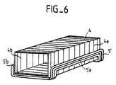
- Figure 6 shows in perspective the relative position of the coil 4 of access and radial servo and a coil 5 'of focus. Only the coils are shown schematically to simplify the figure.
- the sides 4a and 4b are the active portions of the conductor or conductors of the coil 4.
- the parts 5′a and 5′b are the active portions of the conductor, or conductors of the coil 5 ′.
- This embodiment makes it possible to have only one magnetic circuit 13, 12, 6.
- the coil 5 can be constituted by a flat coil folded in a U so as to come to fit under the box 4 d 'access.
- the access and servo device in accordance with the present invention has the advantage of being in one piece and of being able to be produced in a very compact manner, which makes it possible to significantly reduce its weight.
- this device it was possible to eliminate the flexible connections, between the coil 4 and the sliding elements, by using the dynamic viscosity produced by the simultaneous movement of the first motor device and the second motor device.
Description
La présente invention concerne un dispositif d'accès et d'asservissement à une piste portée par un support d'informations lisibles et/ou enregistrables optiquement par un rayonnement focalisé tel qu'un disque optique.The present invention relates to a device for accessing and controlling a track carried by a readable and / or optically recordable information medium by focused radiation such as an optical disc.
En effet, dans le cas de l'écriture et/ou de la lecture d'un disque optique, il est nécessaire à la fois d'accéder à une zone du disque puis de se maintenir dans cette zone avec une bonne précision aussi bien radialement que perpendiculairement à la surface du disque. Ainsi, ces dispositifs de l'art antérieur comportent en général trois dispositifs-moteur séparés.Indeed, in the case of writing and / or reading an optical disc, it is necessary both to access an area of the disc and then to maintain itself in this area with good precision both radially than perpendicular to the surface of the disc. Thus, these devices of the prior art generally comprise three separate motor devices.
Or, pour réaliser l'ensemble des trois fonctions ci-dessus, on a déjà décrit dans le brevet français N°82 03425 un dispositif d'accès et d'asservissement n'utilisant que deux dispositifs- moteur. Dans ce cas, la bobine d'accès est utilisée pour réaliser à la fois les fonctions d'accès et de suivi radial. Toutefois, pour obtenir un bon fonctionnement, il est prévu des moyens de liaison souples entre la bobine et les éléments de glissement de la bobine réalisant l'accès et le suivi radial dans l'entrefer d'un circuit magnétique fixe. En effet, l'utilisation de moyens en simple glissement ne permettait pas d'obtenir une précision de suivi de piste satisfaisante. D'autre part, dans le brevet français N°82 03425, pour éviter que l'opération de focalisation ne s'accompagne d'un effet de diaphragme sur l'optique, les bobines des deux dispositifs moteurs sont reliées l'une à l'autre par l'intermédiaire d'une fixation souple, chaque bobine étant solidaire d'un élément de la tête optique proprement dite. La structure du dispositif d'accès et d'asservissement ainsi réalisé accroît le balourd de l'élément mobile et donc la masse du contre-poids d'équilibrage, ce qui a pour principal inconvénient d'augmenter le poids de la tête.However, to achieve all of the above three functions, there has already been described in French patent No. 82 03425 an access and control device using only two motor devices. In this case, the access coil is used to perform both the access and radial tracking functions. However, to obtain proper operation, flexible connection means are provided between the coil and the sliding elements of the coil providing access and radial tracking in the air gap of a fixed magnetic circuit. Indeed, the use of simple sliding means did not make it possible to obtain satisfactory tracking accuracy. On the other hand, in French patent N ° 82 03425, to prevent the focusing operation from being accompanied by a diaphragm effect on the optics, the coils of the two motor devices are connected to each other. 'other through a flexible attachment, each coil being integral with an element of the optical head itself. The structure of the access and control device thus produced increases the unbalance of the movable element and therefore the mass of the balancing counterweight, which has for main disadvantage of increasing the weight of the head.
On connaît aussi par le brevet Européen A 0287235 un dispositif d'accès et d'asservissement pour disque optique. Dans ce cas, le dispositif d'accès comporte un dispositif de glissement 43, une tête optique 30 et au moins un bras de suspension 44 connectant la tête au dispositif de glissement réalisant l'accès. De plus, une bobine spécifique réalise l'accès et une autre bobine permet le suivi radial.Also known from European patent A 0287235 is an access and servo device for an optical disc. In this case, the access device comprises a
En poursuivant des études sur les dispositifs d'accès et d'asservissement pour disque optique, la Demanderesse s'est aperçue qu'en utilisant une structure monobloc pour l'ensemble formé de la tête optique et des deux bobines prévues dans les dispositifs-moteur pour réaliser l'asservissement et l'accès, il est possible, en utilisant que deux bobines comme cela sera expliqué plus loin, d'éliminer les moyens souples de liaison tout en conservant une excellente précision du positionnement et ainsi d'alléger l'élément mobile, ce qui permet d'accélérer l'accès à la piste.While pursuing studies on the access and servo devices for optical disc, the Applicant has noticed that by using a monobloc structure for the assembly formed by the optical head and the two coils provided in the motor devices to achieve the enslavement and access, it is possible, using only two coils as will be explained below, to eliminate the flexible connecting means while retaining excellent positioning accuracy and thus lighten the element mobile, which speeds up access to the runway.
En conséquence, la présente invention a pour objet un dispositif d'accès et d'asservissement à une piste portée par un support d'informations lisibles et/ou enregistrables optiquement par un rayonnement focalisé, le support d'information comprenant une pluralité de pistes concentriques ou en spirales, ledit dispositif comportant une tête optique d'axe optique orthogonal au plan du support, la tête optique comportant un objectif de focalisation et un moyen de réflection pour réfléchir le faisceau lumineux venant vers le milieu, sensiblement le long de l'axe optique, l'objectif et le moyen de réflexion étant rigidement fixé l'un à l'autre, au moins un premier circuit magnétique fixe comportant au moins un noyau s'étendant dans une direction radiale par rapport auxdites pistes, un premier dispositif moteur permettant l'accès à une piste, le premier dispositif moteur étant constitué par au moins une première bobine montée de manière à se déplacer sur le noyau du circuit magnétique et un deuxième dispositif moteur permettant la focalisation du faisceau lumineux sur la piste, le deuxième dispositif moteur étant constitué d'une deuxième bobine coopérant avec un circuit magnétique, caractérisé en ce que la tête optique, la ou les bobine(s) du premier dispositif moteur et la bobine du second dispositif moteur sont fixées rigidement les unes avec les autres de manière à former un seul équipage mobile.Consequently, the subject of the present invention is a device for accessing and controlling a track carried by a readable information medium and / or optically recordable by a focused radiation, the information medium comprising a plurality of concentric tracks or in spirals, said device comprising an optical head with an optical axis orthogonal to the plane of the support, the optical head comprising a focusing objective and a reflecting means for reflecting the light beam coming towards the middle, substantially along the axis optical, the objective and the reflection means being rigidly fixed to each other, at least a first fixed magnetic circuit comprising at least one core extending in a radial direction relative to said tracks, a first motor device allowing access to a track, the first drive device consisting of at least one first coil mounted so as to move on the core of the magnetic circuit and a second motor device for focusing the light beam on the track, the second motor device consisting of a second coil cooperating with a magnetic circuit, characterized in that the optical head, the coil (s) of the first motor device and the coil of the second motor device are attached rigidly with each other so as to form a single mobile assembly.
Ainsi, avec le dispositif ci-dessus, il n'est plus nécessaire d'utiliser des moyens de liaison souples intercalés entre l'équipage mobile, et les moyens de glissement sur le circuit magnétique d'accès et de suivi radial. En effet, le mouvement d'asservissement de focalisatlon crée une viscosité dynamique sur le suivi radial ou sur le mouvement d'accès et vice et versa. Cette viscosité dynamique s'explique de la façon suivante.Thus, with the above device, it is no longer necessary to use flexible connecting means interposed between the mobile assembly, and the sliding means on the magnetic access and radial tracking circuit. Indeed, the focusing servo movement creates a dynamic viscosity on the radial tracking or on the access movement and vice versa. This dynamic viscosity can be explained as follows.
Lorsqu'un corps solide est en mouvement en s'appuyant sur un autre corps solide, comme le fait la bobine d'accès et d'asservissement radial sur le noyau de son circuit magnétique, une force de frottement, dont la grandeur dépend de la vitesse relative des deux solides, existe à leur surface de contact, que l'on suppose plane. Cette force de frottement solide limite, comme cela est bien connu, la précision de positionnement relatif de ces deux solides.When a solid body is in motion by resting on another solid body, as does the access and radial servo coil on the core of its magnetic circuit, a friction force, the magnitude of which depends on the relative speed of the two solids, exists at their contact surface, which is assumed to be plane. This solid friction force limits, as is well known, the relative positioning precision of these two solids.
Si l'on ajoute maintenant au mouvement utile décrit ci-dessus, un autre mouvement indépendant de ce premier mouvement et lui aussi situé dans le plan de contact des deux solides, le caractère de frottement solide du mouvement utile disparait : une relation linéaire existe alors entre force de frottement et vitesse pour ce mouvement utile, comme dans le cas d'un frottement visqueux. Ce cas de figure s'obtient si l'on superpose sur le même solide les forces générées dans les bobines respectivement utilisées pour la focalisation d'une part et pour l'accès et l'asservissement radial d'autre part.If we now add to the useful movement described above, another movement independent of this first movement and also located in the contact plane of the two solids, the solid friction character of the useful movement disappears: a linear relationship then exists between friction force and speed for this useful movement, as in the case of a viscous friction. This scenario is obtained if one superimposes on the same solid the forces generated in the coils respectively used for the focusing on the one hand and for the access and the radial control on the other hand.
Ainsi, la possibilité d'éliminer les éléments de liaison souples simplifie la réalisation du dispositif d'accès et d'asservissement et permet de plus d'obtenir une meilleure stabilité de la boucle de focalisation.Thus, the possibility of eliminating the flexible connecting elements simplifies the production of the access and control device and also makes it possible to obtain better stability of the focusing loop.
D'autre part, l'équipage mobile est monobloc. Il peut donc être réalisé de façon très compacte et avoir en conséquence une masse très faible. Cela permet d'obtenir des accélérations très élevées et par suite des temps d'accès très courts.On the other hand, the moving equipment is in one piece. It can therefore be made very compactly and therefore have a very low mass. This makes it possible to obtain very high accelerations and consequently very short access times.
Selon une caractéristique de l'invention, le dispositif comporte deux circuits magnétiques coopérant chacun avec une bobine des dispositifs-moteur.According to a characteristic of the invention, the device comprises two magnetic circuits each cooperating with a coil of the motor devices.
D'autre part, selon un mode de réalisation préférentiel, la première bobine est constituée par une bobine cylindrique dont les conducteurs actifs sont dirigés selon l'axe optique de la tête optique et la deuxième bobine est constituée par une boblne, de préférence plate, dont les conducteurs actifs sont dirigés perpendiculairement à l'axe optique. De préférence, la deuxième bobine est fixée rigidement à la bobine cylindrique par l'intermédiaire d'au moins un élément support tel que des entretoises ou des éléments de suspension rigides.On the other hand, according to an embodiment preferably, the first coil consists of a cylindrical coil whose active conductors are directed along the optical axis of the optical head and the second coil consists of a boblne, preferably flat, whose active conductors are directed perpendicular to the optical axis. Preferably, the second coil is rigidly fixed to the cylindrical coil by means of at least one support element such as spacers or rigid suspension elements.
Selon une autre caractéristique de la présente invention, le dispositif d'accès et d'asservissement comporte de plus au moins un dispositif anti-tangage. Ce dispositif anti-tangage entraîne une amélioration de la stabilité angulaire entre l'équipage mobile et le disque.According to another characteristic of the present invention, the access and servo-control device also comprises at least one anti-pitching device. This anti-pitching device improves the angular stability between the moving element and the disc.
Selon un mode de réalisation préférentiel, le dispositif anti-tangage est constitué par une tige fixée à une extrémité de l'équipage mobile et comportant à son autre extrémité au moins un moyen coulissant dans une glissière parallèlement au noyau du premier circuit magnétique.According to a preferred embodiment, the anti-pitching device consists of a rod fixed to one end of the movable assembly and comprising at its other end at least one means sliding in a slide parallel to the core of the first magnetic circuit.
Selon une autre caractéristique supplémentaire de la présente invention, pour localiser le frottement de guidage et améliorer la stabilité angulaire dans les axes correspondant au roulis et au lacet, des petites pièces de matériau à faible coefficient de frottement, par exemple du "téflon", sont fixées à la bobine d'accès et d'asservissement radial et à la bobine de focalisationAccording to another additional characteristic of the present invention, to locate the guide friction and improve the angular stability in the axes corresponding to the roll and the yaw, small pieces of material with a low coefficient of friction, for example "teflon", are fixed to the access and radial servo coil and to the focusing coil
D'autres caractéristiques et avantages de la présente invention apparaîtront à la lecture de la description d'un mode de réalisation préférentiel faite avec référence aux dessins ci-annexés dans lesquels :
- la figure 1 est une vue en coupe schématique d'un dispositif d'accès et d'asservissement pour disque optique incorporé dans le dispositif d'enregistrement-lecture du disque ;
- la figure 2 est une vue en coupe longitudinale d'un dispositif d'accès et d'asservissement conforme à la présente invention ;
- la figure 3 est une vue en coupe transversale du dispositif de figure 2 ;
- la figure 4 est une vue en plan de dessus du premier circuit magnétique,
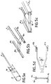
- les figures 5A à 5D représentent différents modes de réalisation d'un dispositif anti-tangage, et
- la figure 6 est une vue en perspective simplifiée d'une variante du dispositif d'accès et d'asservissement suivant l'invention.
- Figure 1 is a schematic sectional view of an access and servo device for optical disc incorporated in the record-read device of the disc;
- Figure 2 is a longitudinal sectional view of an access and servo device according to the present invention;
- Figure 3 is a cross-sectional view of the device Figure 2;
- FIG. 4 is a top plan view of the first magnetic circuit,
- FIGS. 5A to 5D represent different embodiments of an anti-pitching device, and
- Figure 6 is a simplified perspective view of a variant of the access and control device according to the invention.
On a représenté schématiquement sur la figure 1 un dispositif d'accès et d'asservissement à une piste d'un disque optique 1 tournant autour d un axe de rotation A conforme à la présente invention.There is shown diagrammatically in FIG. 1 a device for accessing and controlling a track of an
De manière connue, les informations à lire ou à écrire sont enregistrées selon des cercles concentriques ou sur une spirale formant la piste. A titre d'exemple, cette piste est représentée schématiquement par des sillons ou tours 2 sur la figure 1.In known manner, the information to be read or written is recorded in concentric circles or on a spiral forming the track. As an example, this track is represented diagrammatically by grooves or
Pour lire ou écrire une information et supposant que la focalisation est déjà acquise, on amène le dispositif d'accès et d'asservissement en face du sillon 2 puis l'on asservit en suivi radial le dispositif de manière à ce qu'il reste correctement positionné par rapport à la piste.To read or write information and assuming that focus has already been acquired, the access and servo device is brought in front of the
Comme représenté sur la figure 1, le dispositif d'accès et d'asservissement comporte au moins une tête optique 3 qui sera décrite plus en détail ci-après, une première bobine 4 d'accès et de suivi radial et une deuxième bobine 5 de focalisation. Cet ensemble forme un équipage mobile. Conformément à la présente invention, la tête 3 est connectée de manière fixe à la bobine d'accès et de suivi radial ainsi qu'à la bobine 5 de focalisation. Cet équipage mobile est amené à se déplacer en translation dans les entrefers de deux circuits magnétiques fixes. Pour simplifier le dessin de la figure 1, seul le noyau central 6 du premier circuit magnétique fixe a été représenté. Ce noyau 6 est sécant à tous les sillons ou tours 2 du disque 1 et s'étend sur une longueur égale à au moins la longueur utile d'enregistrement augmentée de la longueur de l'équipage mobile, hormis le dispositif anti-tangage. En effet, les informations sont enregistrées classiquement selon une couronne circulaire. Le premier circuit magnétique en association avec la bobine 4 forme le premier dispositif-moteur permettant l'accès et le suivi de piste. Le deuxième circuit magnétique en association avec la bobine 5 forme le deuxième dispositif-moteur permettant la focalisation. On a omis de représenter sur la figure 1 la source laser, les lentilles de focalisation ou les circuits électroniques associés avec les bobines 4 et 5 pour réaliser les asservissements, car ces circuits sont bien connus de l'homme de l'art.As shown in FIG. 1, the access and servo device comprises at least one
D'autre part, comme représenté sur la figure 1, l'équipage mobile est muni d'un dispositif anti-tangage 7. Ce dispositif 7 est constitué, dans le mode de réalisation représenté, d'une glissière 8 dans laquelle peut coulisser une tige 9 fixée à une extrémité sur l'équipage mobile et portant à son autre extrémité des moyens spécifiques d'anti-tangage dont la forme correspond à la forme de la glissière 8 et qui seront décrits plus en détail ci-après.On the other hand, as shown in Figure 1, the movable assembly is provided with an anti-pitching device 7. This device 7 consists, in the embodiment shown, of a
On décrira maintenant de manière plus détaillée avec référence aux figures 2 à 4, l'équipage mobile et les deux circuits magnétiques fixes permettant de réaliser les deux dispositifs-moteur nécessaires à l'accès et au suivi radial ainsi qu'à la focalisation. Comme représenté sur les figures 2 et 3, la tête optique 3 est constituée plus particulièrement par un élément cylindrique 30 portant à son extrémité supérieure un objectif 31 de focalisation et à son extrémité inférieure un miroir de renvoi 32 destiné à réfléchir le faisceau issu de la source laser vers le disque. L'axe B de la tête est placé orthogonalement au plan du disque. Cette tête 3 est fixée sur un élément support rigide 33 qui est solidarisé avec la bobine 4 du dispositif moteur permettant l'accès et le suivi radial de piste. Comme représenté sur les différentes figures, cette bobine 4 peut être constituée par un bâti cylindrique, d'axe parallèle à un rayon du disque, sur lequel est bobiné au moins un conducteur, dont les spires sont dirigées, dans leur partie active, selon l'axe optique de la tête, c'est-à-dire perpendiculairement à l'axe de la bobine cylindrique. De préférence, la bobine 4 est auto-porteuse, c'est-à-dire qu'elle ne possède pas de bâti et sa rigidité est assurée par le seul collage des spires de son conducteur. Comme représenté sur les figures 3 et 4, la bobine 4 entoure le noyau central 6 du premier circuit magnétique sur lequel elle est amenée à glisser.A more detailed description will now be given with reference to FIGS. 2 to 4, the mobile assembly and the two fixed magnetic circuits making it possible to produce the two motor devices necessary for access and for radial tracking as well as for focusing. As shown in FIGS. 2 and 3, the
D'autre part, comme représenté à la figure 3, deux pièces 40 et 41 sont fixées à la bobine 4 d'accès et de suivi radial. Ces pièces 40 et 41 assurent le guidage de cette bobine sur le noyau 6 de son circuit magnétique pour tout mouvement aussi bien dans la direction d'accès ou radiale que dans la direction de focalisatlon. Associées au dispositif anti-tangage 7, elles permettent de limiter le mouvement de lacet de l'équipage mobile. Comme représenté plus particulièrement à la figure 4, le premier circuit magnétique comporte, en plus du noyau central 6, des aimants droit et gauche 12 fixés sur des pièces polaires 13. Les pièces polaires 13 et le noyau central 6 sont solidarisés ensemble par des barres d'extrémité 14 qui permettent la fermeture du champ aux extrémités de ce dispositif moteur. Dans ce cas, les lignes de champ ont la forme représentée par les lignes avec des flèches 15. En fonction du sens du courant I appliqué aux conducteurs de la bobine 4, l'équipage mobile est amené à se déplacer radialement vers la gauche ou vers la droite sur la figure 1 de manière à venir se positionner en face d'un sillon 2 pour réaliser l'accès puis ensuite à suivre ce sillon en fonction des signaux d'asservissement envoyés.On the other hand, as shown in Figure 3, two
D'autre part, en dessous de la bobine 4 est fixée rigidement par l'intermédiaire d'un système de fixation 17 tel que des équerres ou des éléments rigides, une bobine 5 utilisée pour réaliser la focalisation. Cette bobine 5 est constituée par une bobine plate de forme sensiblement elliptique sur le mode de réalisation de la figure 2. Cette bobine comporte des conducteurs dirigés perpendiculairement à l'axe optique de la tête optique 3. Comme représenté sur la figure 3, la partie inférieure de la bobine 5, à savoir les brins inférieurs des conducteurs 5, est positionnée dans l'entrefer d'un second circuit magnétique fixe dont l'entrefer 18 est parallèle aux entrefers du premier circuit magnétique. Ce second circuit magnétique comporte un aimant 19 et deux pièces polaires 20, l'ensemble présentant une forme de C, dans l'exemple décrit. Dans ce cas, les lignes de champ magnétique sont représentées par la référence 21. Ainsi, lorsque la bobine 5 est parcourue par un courant électrique I, il y a création d'une force F dirigée suivant la direction verticale. Ceci permet de réaliser facilement l'asservissement en focalisation. D'autre part, deux pièces 42 et 43 sont fixées à la bobine de focalisation 5. Elles assurent le guidage de cette bobine dans son circuit magnétique. Associées aux pièces 40 et 41, elles permettent de limiter le mouvement de roulis de l'équipage mobile.On the other hand, below the
D'autre part, comme représenté sur la figure 2, le dispositif de la présente invention comporte un dispositif anti-tangage 7 constitué par une tige 9 munie à son extrémité d'une bille 10 amenée à glisser dans une glissière 8 d'axe sensiblement parallèle à un rayon du disque.On the other hand, as shown in FIG. 2, the device of the present invention comprises an anti-pitching device 7 constituted by a
Comme représenté sur les figures 5A à 5D, différents modes de réalisation peuvent être envisagés pour le dispositif anti-tangage.As shown in FIGS. 5A to 5D, different embodiments can be envisaged for the anti-pitching device.
Dans le mode de réalisation de la figure 5A, le dispositif anti-tangage est constitué par un élément à trois branches 10′ qui coulisse dans une glissière formée par un tube 8.In the embodiment of FIG. 5A, the anti-pitching device is constituted by an element with three
Sur la figure 5B, le dispositif anti-tangage est constitué par deux tétons cylindriques 10a, 10b reliés par des entretoises à la tige 9 et amenés à coulisser dans deux glissières 8a, 8b semi-cylindriques.In FIG. 5B, the anti-pitching device consists of two
Dans le dispositif de la figure 5C, une entretoise 10˝ de section rectangulaire est fixée à l'extrémité de la tige 9 et est amenée à glisser dans deux glissières 8′a, 8′b de section sensiblement en U.In the device of FIG. 5C, a
Sur la figure 5D, le dispositif anti-tangage est constitué de deux branches qui peuvent être dirigées en direction du centre du dispositif d'enregistrement-lecture et passer de chaque côté de l'axe moteur A dimInuant ainsi l'encombrement du dispositif.In FIG. 5D, the anti-pitching device consists of two branches which can be directed in the direction of the center of the recording-reading device and pass on each side of the motor axis A thereby reducing the size of the device.
Les deux glissières 8˝a et 8˝b Sont analogues à celles de la figure 5C. Les deux tétons 10˝a et 10˝b sont de forme parallèlépipédique.The two
Ce dispositif assure à la fois une protection anti-tangage et anti-roulis, comme le permettent aussi les dispositifs des figures 5B et 5C. Avec ces trois dispositifs, les éléments de guidage anti-roulis placés de part et d'autre de la bobine de focalisation peuvent être supprimés.This device provides both anti-pitch and anti-roll protection, as also allowed by the devices of FIGS. 5B and 5C. With these three devices, the anti-roll guide elements placed on either side of the focusing coil can be eliminated.
Il est à noter qu'avec le dispositif anti-tangage dirigé vers le centre du disque, les défauts d'inclinaison de la face du disque, situés dans un plan radial passant par l'axe du disque, peuvent être partiellement corrigés.It should be noted that with the anti-pitching device directed towards the center of the disc, the inclinations of the face of the disc, located in a radial plane passing through the axis of the disc, can be partially corrected.
Il est évident pour l'homme de l'art que d'autres modes de réalisation peuvent être envisagés pour le dispositif anti-tangage.It is obvious to those skilled in the art that other embodiments can be envisaged for the anti-pitching device.
La figure 6 représente en perspective la position relative de la bobine 4 d'accès et d'asservissement radial et d'une bobine 5′ de focalisation. Seules les bobines sont schématisées pour simplifier la figure. Les côtés 4a et 4b sont les portions actives du conducteur ou des conducteurs de la bobine 4. Les parties 5′a et 5′b sont les portions actives du conducteur, ou des conducteurs de la bobine 5′. Ce mode de réalisation permet de n'avoir qu'un seul circuit magnétique 13, 12, 6. Dans ce cas, la bobine 5 peut être constituée par une bobine plate pliée en U de manière à venir s'emboîter sous la boblne 4 d'accès.Figure 6 shows in perspective the relative position of the
Le dispositif d'accès et d'asservissement conforme à la présente invention présente l'avantage d'être monobloc et de pouvoir être réalisé de manière très compacte ce qui permet de diminuer sensiblement son poids. Dans ce dispositif, il a été possible d'éliminer les liaisons souples, entre la bobine 4 et les éléments de glissement, en utilisant la viscosité dynamique produite par le mouvement simultané du premier dispositif moteur et du second dispositif moteur.The access and servo device in accordance with the present invention has the advantage of being in one piece and of being able to be produced in a very compact manner, which makes it possible to significantly reduce its weight. In this device, it was possible to eliminate the flexible connections, between the
Ainsi, à titre d'exemple, en utilisant un objectif de diamètre 6 mm, d'ouverture numérique 0,47 à 0,55, un prisme à réflexion totale pour réaliser la fonction de miroir radiale et des bobinages en fil d'aluminium, on a pu obtenir un équipage mobile présentant une longueur (selon la direction du déplacement radial) de 15 mm, une hauteur (direction de l'axe de rotation du disque) de 26 mm, une largeur de 10 mm et une masse de 3 gr permettant des accélérations de 2000 mètres par seconde au carré.Thus, by way of example, using a 6 mm diameter objective, digital aperture 0.47 to 0.55, a prism with total reflection to perform the function of radial mirror and coils in aluminum wire, it was possible to obtain a mobile assembly having a length (in the direction of the radial displacement) of 15 mm, a height (direction of the axis of rotation of the disc) of 26 mm, a width of 10 mm and a mass of 3 gr allowing accelerations of 2000 meters per second squared.
Claims (11)
- Device for access and for slaving to a track carried by a medium for information which can be read and/or recorded optically by focused radiation, the information medium comprising a plurality of concentric or spiral tracks, the said device including an optical head (3) with optical axis (B) orthogonal to the plane of the medium (1), the optical head including a focusing lens and a reflection means for reflecting the light beam coming towards the medium, substantially along the optical axis, the lens and the reflection means being rigidly fixed to one another, at least one first fixed magnetic circuit (12, 13) including at least one core (6) extending in a radial direction with respect to the said tracks, a first motor device allowing track access and radial tracking, the first motor device consisting of at least one first coil (4) mounted so as to move on the core of the magnetic circuit and a second motor device allowing focusing of the light beam onto the track, the second motor device consisting of a second coil (5) interacting with a magnetic circuit, characterized in that the optical head (3), the coil or coils (4) of the first motor device and the coil (5) of the second motor device are fixed rigidly to one another so as to form a single moving assembly.
- Device according to Claim 1, characterized in that it includes a second fixed magnetic circuit (9, 10) the gap of which forms a plane substantially perpendicular to the medium and crossing all the tracks in which the coil (5) of the second motor device moves.
- Device according to Claim 1, characterized in that it includes a single fixed magnetic circuit (12, 13) consisting of at least one core (6) secant to all the tracks in the gaps of which the coils (4, 5′) of the two motor devices move.
- Device according to either of Claims 1 and 3, characterized in that the first coil (4) consists of a cylindrical coil the active conductors (4a, 4b) of which are directed along the optical axis.
- Device according to any one of Claims 1 to 3, characterized in that the second coil (5) consists of a coil the active conductors of which are directed perpendicularly to the optical axis.
- Device according to either of Claims 4 and 5, characterized in that the second coil is fixed rigidly to the cylindrical coil by means of at least one support element.
- Device according to either of Claims 4 and 5, characterized in that the second coil is shaped so as to fit inside the first coil.
- Device according to any one of Claims 1 to 7, characterized in that it further includes at least one anti-pitch device (7).
- Device according to Claim 8, characterized in that the anti-pitch device consists of at least one rod (9) fixed at one end to the moving assembly and including, at its other end, at least one means (10) sliding in at least one slideway (8) parallel to the core of the first magnetic circuit.
- Device according to any one of Claims 1 to 8, characterized in that it further includes anti-roll and anti-yaw means (40, 41, 42, 43).
- Device according to Claim 10, characterized in that the anti-roll and anti-yaw means consist of pieces made of a material with a low coefficient of friction which are fixed to the coils.
Applications Claiming Priority (2)
| Application Number | Priority Date | Filing Date | Title |
|---|---|---|---|
| FR8908800 | 1989-06-30 | ||
| FR8908800A FR2649238B1 (en) | 1989-06-30 | 1989-06-30 | ACCESS AND CONTROL DEVICE FOR OPTICAL DISC |
Publications (2)
| Publication Number | Publication Date |
|---|---|
| EP0406054A1 EP0406054A1 (en) | 1991-01-02 |
| EP0406054B1 true EP0406054B1 (en) | 1995-11-08 |
Family
ID=9383329
Family Applications (1)
| Application Number | Title | Priority Date | Filing Date |
|---|---|---|---|
| EP19900401673 Expired - Lifetime EP0406054B1 (en) | 1989-06-30 | 1990-06-15 | Access and tracking apparatus for optical disc |
Country Status (5)
| Country | Link |
|---|---|
| EP (1) | EP0406054B1 (en) |
| JP (1) | JPH03130931A (en) |
| CA (1) | CA2019630A1 (en) |
| DE (1) | DE69023397T2 (en) |
| FR (1) | FR2649238B1 (en) |
Families Citing this family (2)
| Publication number | Priority date | Publication date | Assignee | Title |
|---|---|---|---|---|
| FR2683932B1 (en) * | 1991-11-19 | 1993-12-24 | Atg Sa | DEVICE FOR ACCESSING AND TRACKING TRACKS FOR OPTICAL DISCS. |
| JPH08501650A (en) * | 1992-09-23 | 1996-02-20 | コナー ペリフェラルズ インコーポレイテッド | Low height disk drive with 2 1/2 inch form factor |
Family Cites Families (5)
| Publication number | Priority date | Publication date | Assignee | Title |
|---|---|---|---|---|
| JPS57200948A (en) * | 1981-06-02 | 1982-12-09 | Toshiba Corp | Optical information reader |
| JPS6242121U (en) * | 1985-08-30 | 1987-03-13 | ||
| JPS62223822A (en) * | 1986-03-25 | 1987-10-01 | Mitsubishi Electric Corp | Objective lens driving device |
| JPS63257927A (en) * | 1987-04-15 | 1988-10-25 | Pioneer Electronic Corp | Pickup actuator |
| JPS6421728A (en) * | 1987-07-16 | 1989-01-25 | Oki Electric Ind Co Ltd | Optical head |
-
1989
- 1989-06-30 FR FR8908800A patent/FR2649238B1/en not_active Expired - Fee Related
-
1990
- 1990-06-15 DE DE1990623397 patent/DE69023397T2/en not_active Expired - Fee Related
- 1990-06-15 EP EP19900401673 patent/EP0406054B1/en not_active Expired - Lifetime
- 1990-06-22 CA CA 2019630 patent/CA2019630A1/en not_active Abandoned
- 1990-06-29 JP JP17256290A patent/JPH03130931A/en active Pending
Also Published As
| Publication number | Publication date |
|---|---|
| CA2019630A1 (en) | 1990-12-31 |
| FR2649238A1 (en) | 1991-01-04 |
| FR2649238B1 (en) | 1994-06-10 |
| JPH03130931A (en) | 1991-06-04 |
| EP0406054A1 (en) | 1991-01-02 |
| DE69023397T2 (en) | 1996-06-27 |
| DE69023397D1 (en) | 1995-12-14 |
Similar Documents
| Publication | Publication Date | Title |
|---|---|---|
| EP0088662B1 (en) | Optical unit associated with an optical head for reading/writing an optical disc | |
| EP0088010A1 (en) | Device with an optical writing/reading head for an optical disc | |
| EP0055646B1 (en) | Device for optically accessing a track on a movable information carrier | |
| EP0012650A1 (en) | Device for acceding to a track on an optically recordable or readable carrier and optical system comprising such a device | |
| FR2642530A1 (en) | Focusing mechanism and optical head | |
| EP0033052A1 (en) | Optical recording-reproducing device of record carriers and optical memory system comprising such a device | |
| EP0127516A1 (en) | Adjustable mount for a pivoting mirror and optical recording playback head using such a mount | |
| RU2428750C2 (en) | Optical device of information reading, optical disc drive and optical information device | |
| EP0180489B1 (en) | Apparatus for recording and reading information on a magnetic tape | |
| KR19990044345A (en) | Optical scanning device and device provided with the device | |
| EP0406054B1 (en) | Access and tracking apparatus for optical disc | |
| JPS5811692B2 (en) | The current state of affairs | |
| FR2519458A1 (en) | OPTICAL HEAD, IN PARTICULAR FOR READING INFORMATION | |
| EP1449207A2 (en) | Methods and apparatus for optical disk drives | |
| EP0543707B1 (en) | Track access and tracking system for optical disc | |
| FR2615963A1 (en) | DEVICE FOR CONTROLLING THE MOVEMENT OF AN OPTICAL LENS | |
| FR2621411A1 (en) | ASSISTED DEVICE FOR OPTICALLY READING AND MAGNETIC WRITING OF AN INFORMATION CARRIER | |
| EP0036341A1 (en) | Optical system for the realization of special effects on films | |
| US5410433A (en) | Access and follower control device for optical disk | |
| JP2560797Y2 (en) | Optical head device | |
| JPS60254425A (en) | Objective lens driving device used for optical information reader | |
| JP2002156570A (en) | Optical unit supporting device | |
| JP2563768B2 (en) | Objective lens drive | |
| EP0516813A1 (en) | Control device for optical disks | |
| FR2621412A1 (en) | DEVICE FOR OPTICALLY READING AND MAGNETIC WRITING OF AN INFORMATION CARRIER |
Legal Events
| Date | Code | Title | Description |
|---|---|---|---|
| PUAI | Public reference made under article 153(3) epc to a published international application that has entered the european phase |
Free format text: ORIGINAL CODE: 0009012 |
|
| AK | Designated contracting states |
Kind code of ref document: A1 Designated state(s): DE GB IT NL SE |
|
| 17P | Request for examination filed |
Effective date: 19910122 |
|
| 17Q | First examination report despatched |
Effective date: 19930920 |
|
| GRAA | (expected) grant |
Free format text: ORIGINAL CODE: 0009210 |
|
| AK | Designated contracting states |
Kind code of ref document: B1 Designated state(s): DE GB IT NL SE |
|
| REF | Corresponds to: |
Ref document number: 69023397 Country of ref document: DE Date of ref document: 19951214 |
|
| ITF | It: translation for a ep patent filed |
Owner name: BARZANO' E ZANARDO MILANO S.P.A. |
|
| GBT | Gb: translation of ep patent filed (gb section 77(6)(a)/1977) |
Effective date: 19960122 |
|
| PLBE | No opposition filed within time limit |
Free format text: ORIGINAL CODE: 0009261 |
|
| STAA | Information on the status of an ep patent application or granted ep patent |
Free format text: STATUS: NO OPPOSITION FILED WITHIN TIME LIMIT |
|
| 26N | No opposition filed | ||
| PGFP | Annual fee paid to national office [announced via postgrant information from national office to epo] |
Ref country code: GB Payment date: 19991214 Year of fee payment: 10 |
|
| PGFP | Annual fee paid to national office [announced via postgrant information from national office to epo] |
Ref country code: SE Payment date: 19991217 Year of fee payment: 10 |
|
| PGFP | Annual fee paid to national office [announced via postgrant information from national office to epo] |
Ref country code: DE Payment date: 19991224 Year of fee payment: 10 |
|
| PGFP | Annual fee paid to national office [announced via postgrant information from national office to epo] |
Ref country code: NL Payment date: 19991231 Year of fee payment: 10 |
|
| PG25 | Lapsed in a contracting state [announced via postgrant information from national office to epo] |
Ref country code: GB Free format text: LAPSE BECAUSE OF NON-PAYMENT OF DUE FEES Effective date: 20000615 |
|
| PG25 | Lapsed in a contracting state [announced via postgrant information from national office to epo] |
Ref country code: SE Free format text: LAPSE BECAUSE OF NON-PAYMENT OF DUE FEES Effective date: 20000616 |
|
| PG25 | Lapsed in a contracting state [announced via postgrant information from national office to epo] |
Ref country code: NL Free format text: LAPSE BECAUSE OF NON-PAYMENT OF DUE FEES Effective date: 20010101 |
|
| GBPC | Gb: european patent ceased through non-payment of renewal fee |
Effective date: 20000615 |
|
| EUG | Se: european patent has lapsed |
Ref document number: 90401673.0 |
|
| NLV4 | Nl: lapsed or anulled due to non-payment of the annual fee |
Effective date: 20010101 |
|
| PG25 | Lapsed in a contracting state [announced via postgrant information from national office to epo] |
Ref country code: DE Free format text: LAPSE BECAUSE OF NON-PAYMENT OF DUE FEES Effective date: 20010403 |
|
| PG25 | Lapsed in a contracting state [announced via postgrant information from national office to epo] |
Ref country code: IT Free format text: LAPSE BECAUSE OF NON-PAYMENT OF DUE FEES Effective date: 20050615 |