EP0405906A2 - Elektrische Sicherung - Google Patents
Elektrische Sicherung Download PDFInfo
- Publication number
- EP0405906A2 EP0405906A2 EP90306961A EP90306961A EP0405906A2 EP 0405906 A2 EP0405906 A2 EP 0405906A2 EP 90306961 A EP90306961 A EP 90306961A EP 90306961 A EP90306961 A EP 90306961A EP 0405906 A2 EP0405906 A2 EP 0405906A2
- Authority
- EP
- European Patent Office
- Prior art keywords
- seal
- fuse
- end terminal
- annular groove
- groove
- Prior art date
- Legal status (The legal status is an assumption and is not a legal conclusion. Google has not performed a legal analysis and makes no representation as to the accuracy of the status listed.)
- Withdrawn
Links
Images
Classifications
-
- H—ELECTRICITY
- H01—ELECTRIC ELEMENTS
- H01H—ELECTRIC SWITCHES; RELAYS; SELECTORS; EMERGENCY PROTECTIVE DEVICES
- H01H85/00—Protective devices in which the current flows through a part of fusible material and this current is interrupted by displacement of the fusible material when this current becomes excessive
- H01H85/02—Details
- H01H85/04—Fuses, i.e. expendable parts of the protective device, e.g. cartridges
- H01H85/05—Component parts thereof
- H01H85/143—Electrical contacts; Fastening fusible members to such contacts
-
- H—ELECTRICITY
- H01—ELECTRIC ELEMENTS
- H01H—ELECTRIC SWITCHES; RELAYS; SELECTORS; EMERGENCY PROTECTIVE DEVICES
- H01H85/00—Protective devices in which the current flows through a part of fusible material and this current is interrupted by displacement of the fusible material when this current becomes excessive
- H01H85/0013—Means for preventing damage, e.g. by ambient influences to the fuse
- H01H85/0021—Means for preventing damage, e.g. by ambient influences to the fuse water or dustproof devices
- H01H85/003—Means for preventing damage, e.g. by ambient influences to the fuse water or dustproof devices casings for the fusible element
Definitions
- This invention relates to electric fuses.
- an electric fuse it is desirable for an electric fuse to be designed such that the fuse casing and end terminals cooperate with one another to prevent the loss of the pulverulent arc-quenching filler contained with the fuse casing, and, to prevent the escape of products of arcing when the fuse "blows" in response to overcurrent conditions.
- the problem the fuse designer faces is how to prevent the escape of such products of arcing and the arc-quenching filler through the fine annular gap formed between the outer peripheral surface of the plug and the inner surface of the fuse casing.
- US Patent No: 3 250 879 Electric Fuse Comprising Plug Terminals Having an Improved Seal and Pinning Means, proposes an electric fuse having a plug type terminal having a plurality of annular grooves therein for forming a seal with the fuse casing.
- An appropriate sealing medium is introduced through an opening in the fuse casing sidewall which fills the annular grooves to effect a seal.
- the seal material also extends into the openings in the lateral side walls of the fuse casing to effect a "pinning" of the plug terminal to the fuse casing.
- US Patent No: 4 044 326 Hermetic Seal between Telescoping Cylinders of a Fuse Housing, proposes a seal arrangement for a plug type terminal which is achieved by a combination of a resilient gasket member and a settable adhesive filling an annular space between the resilient gasket member and a second gasket member or a structural flange or the like.
- injection techniques wherein the injection is carried out through openings formed in a lateral surface of the fuse casing require compromise of the structural integrity of the casing and lead to a potential vent path for the high pressure products of arcing from the fuse casing, if the seal is not perfectly established.
- an improved sealing arrangement is provided for an electric fuse of the type which has a tubular fuse casing and a fuse end terminal telescopically received within the fuse casing.
- the fuse has an annular seal between the fuse casing and the end terminal which is contained within an annular groove formed in the end terminal.
- the seal is formed from a settable material which has been injected into the groove.
- such an electric fuse is provided with a seal injection opening in the end terminal which extends from the axial outer end of the end terminal and into fluid communication with the annular groove provided in the end terminal.
- a seal material bleed opening is provided in the end terminal which also extends from the axial outer end of the end terminal and into fluid communication with the annular groove. The bleed opening is positioned substantially diametrically opposed to the injection opening.
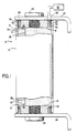
- the fuse 10 is encased in a tubular casing 12 capable of resisting high internal pressures and is made from an electric insulating material such as, for instance, a synthetic resin glass-cloth laminate.
- the laminate in a preferred embodiment, may be a melamine glass-cloth laminate.
- the casing or fuse tube 12 is filled with a granular arc-quenching filler material 14, preferably quartz sand.
- a plurality of steel pins 18 project through openings 20 in the casing 12 and into axially aligned openings 22 in the end terminals 16 to structurally interconnect the end terminals 16 and the casing 12.
- Angular mounting brackets 24, made from silver plated copper, are fixed by means of hex screws 26 to the axial outer surfaces of the terminal plugs 16.
- the fuse casing 12 houses a single longitudinally extending scalloped fusible element 28.
- the fusible element is typically made from a low resistance material such as copper or silver.
- the ends of the fusible element are electrically conductively attached to the inner surfaces 31 of the end terminals by silver plated brass screws 30 threaded into mating openings in the end terminals.
- the connection is heated and a suitable solder 32, is applied to the connection.
- the fuse casing 10 is completely filled with a granular arc-quenching filler 14, in which the fusible element is embedded.
- the filler material is a 30/40 quartz sand.
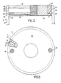
- each terminal is provided with a first circumferentially extending annular groove 36 which is machined into the lateral wall of the end terminal 16 at a position nearet to the interior of the fuse.
- a second circumferentially extending annular groove 38 is machined in the lateral wall of the end terminal 16 at a location spaced axially from the first groove 36 in the direction toward the outer ends of the end terminals 16.
- the first annular groove 36 is approximately .125 inches (0.3175cm) wide, at the end terminals outer lateral surface, and tapers inwardly to a narrower width at its maximum depth. The depth of the groove 36 is also .125 inches (0.3175cm).
- the inward taper of the groove 36 is accomplished by inclining only the sidewall 40 of the groove which is nearest the axial inward end of the end terminal.
- the axial outer side wall 42 of the groove 36 defines a 90 degree angle with respect to the lateral outside wall of the end terminal, while the taper of the inclined side wall 40, is 15 degrees from the horizontal, as viewed in Figure 2.
- This design configuration allows the maximum seal width of .125 inches (0.3175cm) at the interface with the inner surface 44 of the fuse casing 12. At the same time, this allows the root portion of the lower flange like portion of the end terminal to be sufficiently thick to provide it with the necessary structural rigidity to contain the seal as will be described below.
- This arrangement taken with the positioning of the second groove 38, near the outer axial end of the end terminal 16, ensures that, the lateral wall portion 46, which lies between the grooves 36 and 38, is of sufficient width and strength to provide the structural integrity necessary to receive the fuse casing attaching pins 18 described above.
- FIG. 1 shows a schematic representation 52 of the sealant injection apparatus wherein a supply 54 of a settable sealant material, preferably RTV silicone rubber adhesive sealant, has an elongated seal injection nozzle 56 attached thereto which is adapted to be received in the passageway 50, which is designated as the seal injection opening.
- a settable sealant material preferably RTV silicone rubber adhesive sealant
- the lower end 58 of the nozzle 56 is positioned at a location partially extending into the first groove 36 which is designated as the primary seal groove.
- sealant is injected through the nozzle and into the primary seal groove 36.
- the sealant material travels from the point of injection around the first annular groove 36 in both direction at substantially the same rate of travel thereby completely filling the groove 36 with sealant when the two semi-circular paths of sealant material meet one another at the other passageway 48, which is designated as the seal material bleed opening. While Figure 1 shows the seal material being injected into a fuse 10 which is otherwise fully assembled, it should be understood that the seal may be injected at any time during the assembly of the fuse as long as the end terminals have been inserted into and pinned to the fuse casing.
- the sealant may begin to flow into that region. It has been found however, that after the sealant flows into such a region for a short distance, the presence of the sealant material within the region itself, and, the friction of the sealant material with the lateral wall of the plug and the inner wall of the fuse casing begins to display sufficient resistance to sealant flow so that the sealant is prevented from flowing any further into this region. At this time, the path of least resistance, again, continues to be the open unfilled portion of the primary seal groove 36 and the sealant continues to flow into this region.
- the sealant material is RTV 103 Black, silicone rubber adhesive sealant, which is a product of General Electric Company. It has been found that, for any given sealant material, have a given viscosity, there is a minimum cross sectional area of the channel 36 into which the sealant is to be injected that will allow free flow of the material within the channel. For the RTV 103 material such minimum cross sectional area is .0135 in2 (0.087cm2) which is the cross sectional area of the channel 36 described above.
- the above described embodiment provided an effective, low cost, clean and fast arrangement for establishing a reliable, high-integrity seal between an end terminal block and the interior of the fuse casing of an electric fuse into which the block is received.
- Such seal is established in a manner wherein the parts may be handled immediately after injection of the sealant material and wherein the injection technique allows at most a minimal amount of the injected sealant material to pass into the interior of the fuse casing and no sealant material whatsoever may pass through to the axial outer end of the fuse casing or end terminal.
Landscapes
- Fuses (AREA)
Applications Claiming Priority (2)
| Application Number | Priority Date | Filing Date | Title |
|---|---|---|---|
| US372984 | 1989-06-28 | ||
| US07/372,984 US4910490A (en) | 1989-06-28 | 1989-06-28 | End terminal seal for an electric fuse |
Publications (2)
| Publication Number | Publication Date |
|---|---|
| EP0405906A2 true EP0405906A2 (de) | 1991-01-02 |
| EP0405906A3 EP0405906A3 (en) | 1992-04-08 |
Family
ID=23470450
Family Applications (1)
| Application Number | Title | Priority Date | Filing Date |
|---|---|---|---|
| EP19900306961 Withdrawn EP0405906A3 (en) | 1989-06-28 | 1990-06-26 | Electric fuse |
Country Status (4)
| Country | Link |
|---|---|
| US (1) | US4910490A (de) |
| EP (1) | EP0405906A3 (de) |
| JP (1) | JPH0340330A (de) |
| MX (1) | MX172589B (de) |
Families Citing this family (3)
| Publication number | Priority date | Publication date | Assignee | Title |
|---|---|---|---|---|
| JP4175844B2 (ja) * | 2002-08-05 | 2008-11-05 | 大東通信機株式会社 | ヒューズ |
| EP2781269A1 (de) | 2013-03-20 | 2014-09-24 | Eurodrill GmbH | Schwingungserreger, insbesondere für eine Baumaschine |
| DE102015002580B4 (de) | 2015-02-27 | 2019-10-24 | Kathrein Se | Verklebung von Gehäuseteilen |
Family Cites Families (5)
| Publication number | Priority date | Publication date | Assignee | Title |
|---|---|---|---|---|
| US2639350A (en) * | 1950-08-11 | 1953-05-19 | Electric fuse | |
| US2837614A (en) * | 1953-10-19 | 1958-06-03 | Mc Graw Edison Co | Protectors for electric circuits |
| US3250879A (en) * | 1964-06-29 | 1966-05-10 | Chase Shawmut Co | Electric fuse comprising plug terminals having an improved seal and pinning means |
| US4044326A (en) * | 1975-10-09 | 1977-08-23 | General Electric Company | Hermetic seal between telescoping cylinders of a fuse housing |
| US4146862A (en) * | 1977-08-29 | 1979-03-27 | Rte Corporation | Energy limiting oil immersible fuse |
-
1989
- 1989-06-28 US US07/372,984 patent/US4910490A/en not_active Expired - Lifetime
-
1990
- 1990-05-18 JP JP2128952A patent/JPH0340330A/ja active Pending
- 1990-06-20 MX MX021240A patent/MX172589B/es unknown
- 1990-06-26 EP EP19900306961 patent/EP0405906A3/en not_active Withdrawn
Also Published As
| Publication number | Publication date |
|---|---|
| US4910490A (en) | 1990-03-20 |
| JPH0340330A (ja) | 1991-02-21 |
| MX172589B (es) | 1994-01-03 |
| EP0405906A3 (en) | 1992-04-08 |
Similar Documents
| Publication | Publication Date | Title |
|---|---|---|
| US4553807A (en) | Separable electrical connectors with fluid escape path | |
| US10224166B2 (en) | High-current fuse with endbell assembly | |
| DE69700369T2 (de) | Isolierende Zündkerzenkappe | |
| US5046968A (en) | Electrical connector contact having an electrical component disposed in a central internal cavity | |
| KR900013684A (ko) | 차폐단부 접속장치용 댐 | |
| US4910490A (en) | End terminal seal for an electric fuse | |
| US4146862A (en) | Energy limiting oil immersible fuse | |
| WO1990011495A1 (en) | Mounting head for a resistance-tape level sensor | |
| US3558800A (en) | Sealing pigtail connector construction | |
| US5936822A (en) | Coaxial surge arrester | |
| US3277350A (en) | Wet electrolytic encapsulated capacitor | |
| US2333354A (en) | Electric fuse of cartridge type | |
| US3250879A (en) | Electric fuse comprising plug terminals having an improved seal and pinning means | |
| KR20190003083A (ko) | 고전압 퓨즈 | |
| DE29502004U1 (de) | Explosionsgeschützte elektrische Maschine | |
| DE69033410T2 (de) | Zündkerzstecker | |
| US6290239B1 (en) | Seal construction of connector | |
| US4189695A (en) | Current limiting fuse device employing cooling and insulating medium | |
| DE3232333C2 (de) | Niveaufühler für Flüssigkeiten, insbesondere zur Bestimmung des Füllstandes der Bremsflüssigkeit oder des Tankinhaltes in Kraftfahrzeugen | |
| EP0033399A1 (de) | Explosionsgeschützte Halbleiterbauelement-Anordnung | |
| US7122743B2 (en) | Seal for cables and conduits | |
| GB1597506A (en) | Submersible fuse | |
| US3892462A (en) | Plastic high voltage receptacle with embedded metal flange | |
| KR102438378B1 (ko) | 방압 장치를 구비한 서지 피뢰기 | |
| US4401963A (en) | Resistor insertion fuse |
Legal Events
| Date | Code | Title | Description |
|---|---|---|---|
| PUAI | Public reference made under article 153(3) epc to a published international application that has entered the european phase |
Free format text: ORIGINAL CODE: 0009012 |
|
| AK | Designated contracting states |
Kind code of ref document: A2 Designated state(s): DE FR GB |
|
| 17P | Request for examination filed |
Effective date: 19901224 |
|
| PUAL | Search report despatched |
Free format text: ORIGINAL CODE: 0009013 |
|
| AK | Designated contracting states |
Kind code of ref document: A3 Designated state(s): DE FR GB |
|
| STAA | Information on the status of an ep patent application or granted ep patent |
Free format text: STATUS: THE APPLICATION HAS BEEN WITHDRAWN |
|
| 18W | Application withdrawn |
Withdrawal date: 19940504 |