EP0405773A1 - Exterior view mirror for a motor vehicle - Google Patents
Exterior view mirror for a motor vehicle Download PDFInfo
- Publication number
- EP0405773A1 EP0405773A1 EP90306228A EP90306228A EP0405773A1 EP 0405773 A1 EP0405773 A1 EP 0405773A1 EP 90306228 A EP90306228 A EP 90306228A EP 90306228 A EP90306228 A EP 90306228A EP 0405773 A1 EP0405773 A1 EP 0405773A1
- Authority
- EP
- European Patent Office
- Prior art keywords
- formation
- housing
- view mirror
- clutch
- exterior view
- Prior art date
- Legal status (The legal status is an assumption and is not a legal conclusion. Google has not performed a legal analysis and makes no representation as to the accuracy of the status listed.)
- Granted
Links
Images

Classifications
-
- B—PERFORMING OPERATIONS; TRANSPORTING
- B60—VEHICLES IN GENERAL
- B60R—VEHICLES, VEHICLE FITTINGS, OR VEHICLE PARTS, NOT OTHERWISE PROVIDED FOR
- B60R1/00—Optical viewing arrangements; Real-time viewing arrangements for drivers or passengers using optical image capturing systems, e.g. cameras or video systems specially adapted for use in or on vehicles
- B60R1/02—Rear-view mirror arrangements
- B60R1/06—Rear-view mirror arrangements mounted on vehicle exterior
- B60R1/062—Rear-view mirror arrangements mounted on vehicle exterior with remote control for adjusting position
- B60R1/07—Rear-view mirror arrangements mounted on vehicle exterior with remote control for adjusting position by electrically powered actuators
- B60R1/074—Rear-view mirror arrangements mounted on vehicle exterior with remote control for adjusting position by electrically powered actuators for retracting the mirror arrangements to a non-use position alongside the vehicle
Definitions
- This invention relates to an exterior view mirror for a motor vehicle of the type which is adapted to be mounted on the side of the vehicle and to be foldable to a position closely adjacent to the side of the vehicle to facilitate passage of the vehicle through narrow passageways and parking of the vehicle in confined spaces.
- Patent Specification SU-A-1137264 discloses a clutch having a component formed from shape memory alloy and arranged so that when the component is heated by an electrical heater, the driving and driven elements of the clutch disengage from one another. It is also known from Patent Specification EP-A-0173433 that the electrical resisitivity of shape memory alloys of nickel and titanium is such that an element formed therefrom can conveniently be transformed from its relaxed phase to its force-exerting phase by passing an electric current through it.
- a rear view mirror for a motor vehicle comprises a base adapted to mounted on the side of a motor vehicle; a housing pivotally mounted on the base for angular movement between a position in which it projects laterally from the side of the vehicle and a position in which it is located in close proximity to the side of the vehicle, a clutch for securing the housing at a pre-determined orientation relative to the base and remotely operable release means for causing disengagement of the clutch.
- the mirror includes means for causing displacement of the housing away from said predetermined orientation when the clutch is disengaged.
- the mirror may further include remotely operable means for returning the housing to said predetermined orientation.
- the remotely operable return means may comprise a shape memory alloy wire arranged, when heated, to pull the housing into said predetermined orientation.
- the release means may also include a shape memory alloy wire adapted, when heated, to cause disengagement of the clutch.
- a clutch in another aspect, comprises a first member carrying a detent formation, a second member journalled on the first member so as to be axially movable relative thereto to bring the detent formation into engagement with a complementary formation on the second member, a spring for causing relative axial movement between the first member and the second member to bring the detent formation into engagement with the complementary formation and a shape memory alloy wire arranged when heated to oppose the spring to cause disengagement of the detent formation from the complimentary formation.
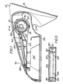
- Figure 1 shows a mirror assembly comprising a base member 12 having a face 14 adapted to abut against the side of a vehicle body.
- a housing 16 is pivotally mounted on base member 12 for angular movement about a vertical axle 18.
- the housing 16 is fixed to an internal frame member 20 which has a hollow cylindrical boss 22 at one end embracing the axle 18 and which carries means 24 (not shown in detail) supporting a reflective member 26 so as to permit adjustment of the orientation of the latter relative to the housing 16.
- the base member 12 has an outwardly projecting portion 30 containing a vertical hole 32.
- a hollow cylindrical member 34 is journalled in the hole 32.
- Figure 4 shows the cylindrical member 34 schmatically and it will be seen that there are four uniformly spaced grooves 36, 38, 40 and 42 in the cylindrical face extending parallel to the cylinder axis.
- the cylindrical member 34 On its lower end, has a flange 44 which is secured to the surface surrounding the hole 32 on lower side of the base member 12.
- a tubular member 46 extends through a central hole 48 in the top of the cylindrical member 34 and is fast with an upper end cap 50 having a downwardly extending cylindrical flange 52.
- the lower end of the tubular member 46 is secured to a lower end cap 54.
- the lower end cap 54 has a keyway 56 which is engaged by a spline 58 on the inner surface of the cylindrical member 34.
- the cylindrical flange 52 of the upper end member has a keyway 60 engaged by a spline 62 on the outer surface of the cylindrical member 34.
- a compression spring 64 engages with the lower end cap 54 so as to bias it downwardly relative to the tubular member 34.
- the bottom edge of the flange 52 on the upper end cap 50 engages with a flange 66 on the inside of the boss 22 with the result that the compression spring 64 has the effect of urging the bottom surface of the boss 22 into engagement with the top surface of the bracket 12.
- a V-shaped detent formation 70 on the bottom surface of the boss 22 engages in a V-shaped groove 72 in the top surface of the bracket 12 when the mirror housing 16 is at its orientation of normal use relative to the base member 12. Displacement of the housing 16 from this orientation is, therefore, resisted by the compression spring 64.
- a shape memory alloy wire 74 passes through an opening in the bottom end cap 54, up the groove 38 in the cylindrical member 34, across the top thereof, down the groove 36, across the bottom of the bottom end cap 54, up the groove 42, across the top of the cylindrical member 34 and finally down through the groove 40 and the end cap 54.
- the two ends of the wire 74 are fixed to the end cap 54 where they pass through it.
- the length of the shape memory alloy wire 74 is adjusted so that, if it is heated above its transition temperature, e.g., by passage of an electric current, it contracts, drawing the end cap 54 upwardly towards the cylindrical member 34 against the action of the compression spring 64.
- a torsion spring 76 engages between a hole 78 in the boss 22 and a slot 80 in the flange 52 on the end cap 50 so as to cause displacement of the housing 16 to a position in which the reflective member 26 is in substantial alignment with the face 14 on the base member 12.
- the upper end cap 50 has a projection 82.
- a second shape memory alloy wire 84 has one end attached to the projection 82 and the other to a link 86 which is pivotally mounted on a pin 88 projecting from the frame member 20.
- a third shape memory alloy wire 90 extends from the other end of the link 86 to a second link 92 which is pivotally mounted on a pin 94 also secured to the frame member 20.
- a fourth shape memory alloy wire 96 extends from the other end of the link 92 to the first pivot pin 88.
- the length of the wires 84, 90 and 96 are arranged to be such that, when heated above their transition temperature, e.g., by passing an electric current through them, they pull the housing 16 into a position in which the detent 70 can engage in the groove 72 against the action of the torsion spring 76.
- the V-shaped detent 70 engages in the groove 72, holding the housing 16 in its orientation of normal use relative to the base member 12. If it is desired to fold the housing 16 into close proximity of the vehicle, an electric current is connected to heat the first shape memory alloy wire 74, causing it to contract, thereby compressing the spring 64. The force exerted by the torsion spring 76 is sufficient to lift the detent 70 out of the groove 72 and then displace the housing 16 in the counter-clockwise direction as viewed in Figure 1.
- the other shape memory alloy wires 84, 90 and 96 are heated by passing an electric current through them. This draws the housing back to its position of normal use (illustrated in Figure 1) against the action of the torsion spring 76. In order to reduce friction caused by the compression spring 64, it is desirable also to heat the first shape memory alloy wire 74 while the housing is returned to its position of normal use.
- the second, third and fourth shape memory alloy wires 84, 90 and 96 may be replaced by a single shape memory alloy wire, the distance of the projection 82 from the pivot axis being reduced by one third. This has the advantage of simplifying the mechanism. However, such single shape memory alloy wire must be capable of exerting three times the force exerted by the wires 84, 90 and 96 and consequently it must be made thicker.
- straight shape memory alloy wires (rather than coiled springs) has the advantage that the heat treatment of such wire during manufacture may be done as a continuous process, with wired wound round large-diameter rollers, rather than each spring having to be subject to individual heat treatment under stress.
Landscapes
- Engineering & Computer Science (AREA)
- Multimedia (AREA)
- Mechanical Engineering (AREA)
- Rear-View Mirror Devices That Are Mounted On The Exterior Of The Vehicle (AREA)
Abstract
Description
- This invention relates to an exterior view mirror for a motor vehicle of the type which is adapted to be mounted on the side of the vehicle and to be foldable to a position closely adjacent to the side of the vehicle to facilitate passage of the vehicle through narrow passageways and parking of the vehicle in confined spaces.
- Patent Specification SU-A-1137264 discloses a clutch having a component formed from shape memory alloy and arranged so that when the component is heated by an electrical heater, the driving and driven elements of the clutch disengage from one another. It is also known from Patent Specification EP-A-0173433 that the electrical resisitivity of shape memory alloys of nickel and titanium is such that an element formed therefrom can conveniently be transformed from its relaxed phase to its force-exerting phase by passing an electric current through it.
- According to the invention, in one aspect, a rear view mirror for a motor vehicle comprises a base adapted to mounted on the side of a motor vehicle; a housing pivotally mounted on the base for angular movement between a position in which it projects laterally from the side of the vehicle and a position in which it is located in close proximity to the side of the vehicle, a clutch for securing the housing at a pre-determined orientation relative to the base and remotely operable release means for causing disengagement of the clutch.
- Preferably, the mirror includes means for causing displacement of the housing away from said predetermined orientation when the clutch is disengaged. The mirror may further include remotely operable means for returning the housing to said predetermined orientation. The remotely operable return means may comprise a shape memory alloy wire arranged, when heated, to pull the housing into said predetermined orientation. The release means may also include a shape memory alloy wire adapted, when heated, to cause disengagement of the clutch.
- According to the invention in another aspect, a clutch comprises a first member carrying a detent formation, a second member journalled on the first member so as to be axially movable relative thereto to bring the detent formation into engagement with a complementary formation on the second member, a spring for causing relative axial movement between the first member and the second member to bring the detent formation into engagement with the complementary formation and a shape memory alloy wire arranged when heated to oppose the spring to cause disengagement of the detent formation from the complimentary formation.
- An embodiment of the invention will now be described, by way of example, with reference to the accompanying drawings, in which:
- Figure 1 is a horizontal sectional view of a rear view mirror for a motor vehicle in accordance with the invention;
- Figure 2 is a sectional view taken on the line 2 - 2 in Figure 1;
- Figure 3 is a scrap sectional view taken on the line 3 - 3 in Figure 2;
- Figure 4 is a schematic perspective view of some of the components shown in Figure 2; and
- Figure 5 is a scrap sectional view of part of the mirror assembly shown in Figure 1.
- Figure 1 shows a mirror assembly comprising a
base member 12 having aface 14 adapted to abut against the side of a vehicle body. Ahousing 16 is pivotally mounted onbase member 12 for angular movement about avertical axle 18. Thehousing 16 is fixed to aninternal frame member 20 which has a hollowcylindrical boss 22 at one end embracing theaxle 18 and which carries means 24 (not shown in detail) supporting areflective member 26 so as to permit adjustment of the orientation of the latter relative to thehousing 16. - Referring to Figure 2, the
base member 12 has an outwardly projectingportion 30 containing avertical hole 32. A hollowcylindrical member 34 is journalled in thehole 32. Figure 4 shows thecylindrical member 34 schmatically and it will be seen that there are four uniformly spacedgrooves cylindrical member 34 has aflange 44 which is secured to the surface surrounding thehole 32 on lower side of thebase member 12. - A
tubular member 46 extends through a central hole 48 in the top of thecylindrical member 34 and is fast with anupper end cap 50 having a downwardly extendingcylindrical flange 52. The lower end of thetubular member 46 is secured to alower end cap 54. Thelower end cap 54 has a keyway 56 which is engaged by aspline 58 on the inner surface of thecylindrical member 34. Similarly, thecylindrical flange 52 of the upper end member has a keyway 60 engaged by a spline 62 on the outer surface of thecylindrical member 34. The result is that the assembly comprising thetubular member 46 and itsend caps cylindrical member 34 but is constrained against relative angular movement about their common axis. Acompression spring 64 engages with thelower end cap 54 so as to bias it downwardly relative to thetubular member 34. The bottom edge of theflange 52 on theupper end cap 50 engages with aflange 66 on the inside of theboss 22 with the result that thecompression spring 64 has the effect of urging the bottom surface of theboss 22 into engagement with the top surface of thebracket 12. A V-shaped detent formation 70 on the bottom surface of theboss 22 engages in a V-shaped groove 72 in the top surface of thebracket 12 when themirror housing 16 is at its orientation of normal use relative to thebase member 12. Displacement of thehousing 16 from this orientation is, therefore, resisted by thecompression spring 64. - As can be seen from Figure 4, a shape
memory alloy wire 74 passes through an opening in thebottom end cap 54, up the groove 38 in thecylindrical member 34, across the top thereof, down thegroove 36, across the bottom of thebottom end cap 54, up thegroove 42, across the top of thecylindrical member 34 and finally down through thegroove 40 and theend cap 54. The two ends of thewire 74 are fixed to theend cap 54 where they pass through it. The length of the shapememory alloy wire 74 is adjusted so that, if it is heated above its transition temperature, e.g., by passage of an electric current, it contracts, drawing theend cap 54 upwardly towards thecylindrical member 34 against the action of thecompression spring 64. This reduces the force resisting displacement of the V-shaped detent formation 70 out of thegroove 72 to that exerted by the weight of thehousing 16. Atorsion spring 76 engages between ahole 78 in theboss 22 and aslot 80 in theflange 52 on theend cap 50 so as to cause displacement of thehousing 16 to a position in which thereflective member 26 is in substantial alignment with theface 14 on thebase member 12. - As can be seen in Figures 1 and 2, the
upper end cap 50 has aprojection 82. Referring particularly to Figures 1 and 5, a second shapememory alloy wire 84 has one end attached to theprojection 82 and the other to alink 86 which is pivotally mounted on apin 88 projecting from theframe member 20. A third shapememory alloy wire 90 extends from the other end of thelink 86 to asecond link 92 which is pivotally mounted on apin 94 also secured to theframe member 20. A fourth shapememory alloy wire 96 extends from the other end of thelink 92 to thefirst pivot pin 88. The length of thewires housing 16 into a position in which the detent 70 can engage in thegroove 72 against the action of thetorsion spring 76. - In normal use, the V-
shaped detent 70 engages in thegroove 72, holding thehousing 16 in its orientation of normal use relative to thebase member 12. If it is desired to fold thehousing 16 into close proximity of the vehicle, an electric current is connected to heat the first shapememory alloy wire 74, causing it to contract, thereby compressing thespring 64. The force exerted by thetorsion spring 76 is sufficient to lift the detent 70 out of thegroove 72 and then displace thehousing 16 in the counter-clockwise direction as viewed in Figure 1. - To restore the
housing 16 to its position of normal use, the other shapememory alloy wires torsion spring 76. In order to reduce friction caused by thecompression spring 64, it is desirable also to heat the first shapememory alloy wire 74 while the housing is returned to its position of normal use. - The second, third and fourth shape
memory alloy wires projection 82 from the pivot axis being reduced by one third. This has the advantage of simplifying the mechanism. However, such single shape memory alloy wire must be capable of exerting three times the force exerted by thewires - The use of straight shape memory alloy wires (rather than coiled springs) has the advantage that the heat treatment of such wire during manufacture may be done as a continuous process, with wired wound round large-diameter rollers, rather than each spring having to be subject to individual heat treatment under stress.
Claims (9)
Applications Claiming Priority (2)
| Application Number | Priority Date | Filing Date | Title |
|---|---|---|---|
| GB898914707A GB8914707D0 (en) | 1989-06-27 | 1989-06-27 | Exterior view mirror for a motor vehicle |
| GB8914707 | 1989-06-27 |
Publications (2)
| Publication Number | Publication Date |
|---|---|
| EP0405773A1 true EP0405773A1 (en) | 1991-01-02 |
| EP0405773B1 EP0405773B1 (en) | 1993-08-18 |
Family
ID=10659109
Family Applications (1)
| Application Number | Title | Priority Date | Filing Date |
|---|---|---|---|
| EP90306228A Expired - Lifetime EP0405773B1 (en) | 1989-06-27 | 1990-06-07 | Exterior view mirror for a motor vehicle |
Country Status (6)
| Country | Link |
|---|---|
| US (1) | US5166832A (en) |
| EP (1) | EP0405773B1 (en) |
| JP (1) | JPH03135852A (en) |
| AU (1) | AU5776390A (en) |
| DE (1) | DE69002804T2 (en) |
| GB (1) | GB8914707D0 (en) |
Cited By (8)
| Publication number | Priority date | Publication date | Assignee | Title |
|---|---|---|---|---|
| EP0551607A1 (en) * | 1991-12-13 | 1993-07-21 | Hohe Kg | Exterior mirror for a motor vehicle with locking device |
| WO1995016589A1 (en) * | 1993-12-15 | 1995-06-22 | Poong Jeong Ind. Co., Ltd. | Device for regulating motor-driven foldable rear view mirror of automobile |
| EP0713804A1 (en) * | 1994-11-26 | 1996-05-29 | Britax (Geco) S.A. | Exterior rear view mirror for a vehicle |
| EP0897831A3 (en) * | 1997-08-01 | 1999-07-28 | C.R.F. Società Consortile per Azioni | Motor-vehicle outer rear view mirror having a shape memory actuating device |
| US6371619B1 (en) | 1999-03-22 | 2002-04-16 | Britax Wingard Limited | Vehicle exterior mirror |
| EP3168468A1 (en) * | 2015-11-12 | 2017-05-17 | SMR Patents S.à.r.l. | Rear view element folding device |
| US10059266B2 (en) * | 2015-05-12 | 2018-08-28 | SMR Patents S.à.r.l. | Adjustment unit, rear view device and vehicle |
| EP3530523A1 (en) * | 2018-02-22 | 2019-08-28 | SMR Patents S.à.r.l. | Rear view element folding device |
Families Citing this family (32)
| Publication number | Priority date | Publication date | Assignee | Title |
|---|---|---|---|---|
| KR930009203B1 (en) * | 1991-12-30 | 1993-09-24 | 조성호 | Rear-view mirror |
| US5734517A (en) * | 1993-12-15 | 1998-03-31 | Poong Jeong Ind. Co., Ltd. | Device for regulating motor-driven foldable rear view mirror of automobile |
| US5639054A (en) * | 1994-11-02 | 1997-06-17 | United Technologies Automotive Systems, Inc. | Pivot mount for exterior side-mounted rearview mirror |
| CA2346260A1 (en) * | 1998-10-23 | 2000-05-04 | Magna Mirror Systems Inc. | Shape memory alloy rearview mirror |
| IT1305590B1 (en) * | 1998-12-23 | 2001-05-09 | Magneti Marelli Spa | REAR-VIEW MIRROR FOR MOTOR VEHICLES WITH ACTUATOR-CLOTHING DEVICE, WITH MEMORY OF SHAPE. |
| US6902048B1 (en) | 1999-04-14 | 2005-06-07 | Caleb Chung | Clutch |
| KR20020021809A (en) * | 1999-08-12 | 2002-03-22 | 추후기재 | Shape-memory alloy actuators and control methods |
| US6555222B1 (en) | 2000-01-13 | 2003-04-29 | Schefenacker Vision Systems France Sa | Reinforced polypropylene mirror assembly and process for making the same |
| WO2002068820A1 (en) | 2001-02-22 | 2002-09-06 | Nanomuscle, Inc. | Shape memory alloy actuator with improved temperature control |
| CN1659063A (en) * | 2002-04-09 | 2005-08-24 | 麦格纳唐纳尼车镜北美有限责任公司 | Vehicular mirror actuator with single motor actuation |
| EP1576255A1 (en) * | 2002-05-06 | 2005-09-21 | Alfmeier Präzision Ag Baugruppen und Systemlösungen | High stroke, highly integrated sma actuators |
| WO2003093615A1 (en) | 2002-05-06 | 2003-11-13 | Nanomuscle, Inc. | Reusable shape memory alloy activated latch |
| KR20040106494A (en) * | 2002-05-06 | 2004-12-17 | 나노머슬, 인크. | Actuator for two angular degrees of freedom |
| US8127543B2 (en) * | 2002-05-06 | 2012-03-06 | Alfmeier Prazision Ag Baugruppen Und Systemlosungen | Methods of manufacturing highly integrated SMA actuators |
| KR20060005403A (en) | 2003-04-28 | 2006-01-17 | 나노머슬, 인크. | Flow control assembly with integrally formed shape memory alloy actuator |
| JP2006525526A (en) * | 2003-05-02 | 2006-11-09 | アルフマイヤー プレチジオーン アクチエンゲゼルシャフト バウグルッペン ウント ジステームレーズンゲン | Gauge indicating needle with integrated shape memory alloy actuator |
| WO2005026592A2 (en) | 2003-09-05 | 2005-03-24 | Alfmeier Präzision AG Baugruppen und Systemlösungen | A system, method and apparatus for reducing frictional forces and for compensating shape memory alloy-actuated valves and valve systems at high temperatures |
| JP2005199820A (en) * | 2004-01-14 | 2005-07-28 | Ichikoh Ind Ltd | Mirror device for vehicle |
| US7858891B2 (en) * | 2006-04-24 | 2010-12-28 | Volkswagen Group Of America, Inc. | Shape-changing control panel button based on activation/deactivation |
| US7834303B2 (en) * | 2008-06-09 | 2010-11-16 | Ahura Energy Concentrating Systems | Multi-element concentrator system |
| KR101364848B1 (en) | 2009-12-28 | 2014-02-19 | 케논 콤포넨트 가부시키가이샤 | Contact-type image sensor unit and image reading device using same |
| JP5139507B2 (en) | 2010-12-10 | 2013-02-06 | キヤノン・コンポーネンツ株式会社 | Image sensor unit and image reading apparatus |
| JP5204207B2 (en) | 2010-12-17 | 2013-06-05 | キヤノン・コンポーネンツ株式会社 | Image sensor unit and image reading apparatus using the same |
| JP5244952B2 (en) | 2010-12-21 | 2013-07-24 | キヤノン・コンポーネンツ株式会社 | Image sensor unit and image reading apparatus |
| JP5384471B2 (en) | 2010-12-28 | 2014-01-08 | キヤノン・コンポーネンツ株式会社 | Image sensor unit and image reading apparatus |
| JP5400188B2 (en) * | 2011-05-11 | 2014-01-29 | キヤノン・コンポーネンツ株式会社 | Image sensor unit and image reading apparatus and image forming apparatus using the same |
| JP5518953B2 (en) | 2011-08-09 | 2014-06-11 | キヤノン・コンポーネンツ株式会社 | Image sensor unit and image reading apparatus |
| EP2771969A4 (en) * | 2011-10-26 | 2015-09-16 | Autosplice Inc | Shape memory alloy powered apparatus and method for making and constructing the apparatus |
| EP3093196B1 (en) * | 2015-05-12 | 2017-08-23 | SMR Patents S.à.r.l. | Adjustable rear viewing device, method and motor vehicle |
| RU180714U1 (en) * | 2018-04-10 | 2018-06-21 | Общество с ограниченной ответственностью "ИПРОСС" | Outside rearview mirror |
| RU200659U1 (en) * | 2020-07-27 | 2020-11-03 | Общество с ограниченной ответственностью "Центр технологических разработок "ТИМЕР" (ООО "ЦТР "ТИМЕР") | ROTARY ASSEMBLY REAR VIEW MIRRORS |
| US12522138B2 (en) * | 2022-04-05 | 2026-01-13 | Magna Mirrors Of America, Inc. | Vehicular exterior mirror assembly with dual/nested coil spring at pivot joint |
Citations (4)
| Publication number | Priority date | Publication date | Assignee | Title |
|---|---|---|---|---|
| DE2042103A1 (en) * | 1970-08-19 | 1972-03-02 | Yorck Talbot | Safety holding device for components or accessories mounted in or on vehicles, such as rearview mirrors |
| EP0173433A1 (en) * | 1984-07-21 | 1986-03-05 | B.S.G. Overseas Limited | Remote control system |
| US4786157A (en) * | 1986-03-01 | 1988-11-22 | Aisin Seiki Kabushiki Kaisha | Electrically operated automobile mirror assembly |
| EP0305590A1 (en) * | 1984-06-28 | 1989-03-08 | Murakami Kaimeido Co., Ltd | Electrically foldable door mirror |
Family Cites Families (6)
| Publication number | Priority date | Publication date | Assignee | Title |
|---|---|---|---|---|
| SU1137264A1 (en) * | 1984-01-02 | 1985-01-30 | Московский Ордена Ленина И Ордена Октябрьской Революции Авиационный Институт Им.Серго Орджоникидзе | Thermally controlled friction clutch |
| JPS60148738A (en) * | 1984-01-12 | 1985-08-06 | Ichikoh Ind Ltd | Door mirror structure |
| US4657362A (en) * | 1984-02-27 | 1987-04-14 | Kabushiki Kaisha Tokai Riki Denki Seisakusho | Door mirror |
| JPH0355464Y2 (en) * | 1984-11-06 | 1991-12-10 | ||
| US4692000A (en) * | 1984-11-12 | 1987-09-08 | Ichikoh Industries, Ltd. | Motor-driven collapsible door mirror |
| JPS63173745A (en) * | 1987-01-13 | 1988-07-18 | Murakami Kaimeidou:Kk | Electric flexible door mirror |
-
1989
- 1989-06-27 GB GB898914707A patent/GB8914707D0/en active Pending
-
1990
- 1990-06-07 EP EP90306228A patent/EP0405773B1/en not_active Expired - Lifetime
- 1990-06-07 DE DE90306228T patent/DE69002804T2/en not_active Expired - Fee Related
- 1990-06-25 AU AU57763/90A patent/AU5776390A/en not_active Abandoned
- 1990-06-26 US US07/543,456 patent/US5166832A/en not_active Expired - Fee Related
- 1990-06-27 JP JP2169659A patent/JPH03135852A/en active Pending
Patent Citations (4)
| Publication number | Priority date | Publication date | Assignee | Title |
|---|---|---|---|---|
| DE2042103A1 (en) * | 1970-08-19 | 1972-03-02 | Yorck Talbot | Safety holding device for components or accessories mounted in or on vehicles, such as rearview mirrors |
| EP0305590A1 (en) * | 1984-06-28 | 1989-03-08 | Murakami Kaimeido Co., Ltd | Electrically foldable door mirror |
| EP0173433A1 (en) * | 1984-07-21 | 1986-03-05 | B.S.G. Overseas Limited | Remote control system |
| US4786157A (en) * | 1986-03-01 | 1988-11-22 | Aisin Seiki Kabushiki Kaisha | Electrically operated automobile mirror assembly |
Cited By (12)
| Publication number | Priority date | Publication date | Assignee | Title |
|---|---|---|---|---|
| EP0551607A1 (en) * | 1991-12-13 | 1993-07-21 | Hohe Kg | Exterior mirror for a motor vehicle with locking device |
| WO1995016589A1 (en) * | 1993-12-15 | 1995-06-22 | Poong Jeong Ind. Co., Ltd. | Device for regulating motor-driven foldable rear view mirror of automobile |
| EP0682606B1 (en) * | 1993-12-15 | 1997-07-09 | Poong Jeong Ind. Co., Ltd. | Device for regulating motor-driven foldable rear view mirror of automobile |
| EP0713804A1 (en) * | 1994-11-26 | 1996-05-29 | Britax (Geco) S.A. | Exterior rear view mirror for a vehicle |
| US5828504A (en) * | 1994-11-26 | 1998-10-27 | Britax (Geco) S.A. | Exterior rearview mirror for a vehicle |
| EP0897831A3 (en) * | 1997-08-01 | 1999-07-28 | C.R.F. Società Consortile per Azioni | Motor-vehicle outer rear view mirror having a shape memory actuating device |
| US6371619B1 (en) | 1999-03-22 | 2002-04-16 | Britax Wingard Limited | Vehicle exterior mirror |
| US6609800B2 (en) | 1999-03-22 | 2003-08-26 | Schefenacker Vision Systems Uk Limited | Vehicle exterior mirror |
| US10059266B2 (en) * | 2015-05-12 | 2018-08-28 | SMR Patents S.à.r.l. | Adjustment unit, rear view device and vehicle |
| EP3168468A1 (en) * | 2015-11-12 | 2017-05-17 | SMR Patents S.à.r.l. | Rear view element folding device |
| EP3301298A1 (en) | 2015-11-12 | 2018-04-04 | SMR Patents S.à.r.l. | Rear view element folding device |
| EP3530523A1 (en) * | 2018-02-22 | 2019-08-28 | SMR Patents S.à.r.l. | Rear view element folding device |
Also Published As
| Publication number | Publication date |
|---|---|
| DE69002804T2 (en) | 1994-03-10 |
| GB8914707D0 (en) | 1989-08-16 |
| AU5776390A (en) | 1991-01-03 |
| DE69002804D1 (en) | 1993-09-23 |
| EP0405773B1 (en) | 1993-08-18 |
| JPH03135852A (en) | 1991-06-10 |
| US5166832A (en) | 1992-11-24 |
Similar Documents
| Publication | Publication Date | Title |
|---|---|---|
| EP0405773B1 (en) | Exterior view mirror for a motor vehicle | |
| US4567549A (en) | Automatic takeup and overload protection device for shape memory metal actuator | |
| US6364496B1 (en) | Shape memory alloy rearview mirror | |
| JP3372274B2 (en) | Drive device for rearview mirror | |
| JP2000506806A (en) | External mirror with index function and control pivot function | |
| US5477391A (en) | Mirror assembly movable into rearwardly folded position with reversing spring bias | |
| EP0801609B1 (en) | Exterior mirror with single pivot power fold | |
| US4027953A (en) | Switch controlled adjustable rear view mirror with bimetal means | |
| US4456333A (en) | Side view mirror for vehicles | |
| EP0173433A1 (en) | Remote control system | |
| US5121678A (en) | Ejector grating for electric toaster | |
| EP1213185B1 (en) | Retractable ladder | |
| EP0895885B1 (en) | Device for driving a rotatable deflector, particularly for a motor-vehicle climatization system | |
| US11492049B2 (en) | Hinge assembly for a vehicle hood | |
| US4497084A (en) | Windscreen-wiper element comprising a windscreen-wiper arm subjected to the action of a compression spring by means of a stop bracket | |
| GB1103940A (en) | Adjustable steering column assemblies in motor vehicles | |
| GB1600425A (en) | Motor vehicle rear-view mirrors | |
| JP2596719B2 (en) | Structure used in seat belt retractor and method of manufacturing the same | |
| WO2002074575A1 (en) | A support arrangement for a vehicle seat | |
| EP1031444B1 (en) | Control device with a shape memory actuating member heated by induction | |
| EP0094943B1 (en) | Gear operated remote control mirror | |
| US1842476A (en) | Engine control mechanism | |
| EP0897831B1 (en) | Motor-vehicle outer rear view mirror having a shape memory actuating device | |
| CN215826602U (en) | Rearview mirror connecting mechanism capable of preventing malicious adjustment | |
| JPS58214432A (en) | Supporting body fitted with reset for keeping angle |
Legal Events
| Date | Code | Title | Description |
|---|---|---|---|
| PUAI | Public reference made under article 153(3) epc to a published international application that has entered the european phase |
Free format text: ORIGINAL CODE: 0009012 |
|
| AK | Designated contracting states |
Kind code of ref document: A1 Designated state(s): DE ES FR GB |
|
| 17P | Request for examination filed |
Effective date: 19901219 |
|
| 17Q | First examination report despatched |
Effective date: 19920722 |
|
| GRAA | (expected) grant |
Free format text: ORIGINAL CODE: 0009210 |
|
| AK | Designated contracting states |
Kind code of ref document: B1 Designated state(s): DE FR GB |
|
| RBV | Designated contracting states (corrected) |
Designated state(s): DE FR GB |
|
| REF | Corresponds to: |
Ref document number: 69002804 Country of ref document: DE Date of ref document: 19930923 |
|
| ET | Fr: translation filed | ||
| PLBE | No opposition filed within time limit |
Free format text: ORIGINAL CODE: 0009261 |
|
| STAA | Information on the status of an ep patent application or granted ep patent |
Free format text: STATUS: NO OPPOSITION FILED WITHIN TIME LIMIT |
|
| 26N | No opposition filed | ||
| PGFP | Annual fee paid to national office [announced via postgrant information from national office to epo] |
Ref country code: GB Payment date: 19950530 Year of fee payment: 6 |
|
| PGFP | Annual fee paid to national office [announced via postgrant information from national office to epo] |
Ref country code: DE Payment date: 19950607 Year of fee payment: 6 |
|
| PGFP | Annual fee paid to national office [announced via postgrant information from national office to epo] |
Ref country code: FR Payment date: 19950609 Year of fee payment: 6 |
|
| PG25 | Lapsed in a contracting state [announced via postgrant information from national office to epo] |
Ref country code: GB Effective date: 19960607 |
|
| GBPC | Gb: european patent ceased through non-payment of renewal fee |
Effective date: 19960607 |
|
| PG25 | Lapsed in a contracting state [announced via postgrant information from national office to epo] |
Ref country code: FR Effective date: 19970228 |
|
| PG25 | Lapsed in a contracting state [announced via postgrant information from national office to epo] |
Ref country code: DE Effective date: 19970301 |
|
| REG | Reference to a national code |
Ref country code: FR Ref legal event code: ST |