EP0405662B1 - Receiver for data transmission system with nonlinearities - Google Patents
Receiver for data transmission system with nonlinearities Download PDFInfo
- Publication number
- EP0405662B1 EP0405662B1 EP90201631A EP90201631A EP0405662B1 EP 0405662 B1 EP0405662 B1 EP 0405662B1 EP 90201631 A EP90201631 A EP 90201631A EP 90201631 A EP90201631 A EP 90201631A EP 0405662 B1 EP0405662 B1 EP 0405662B1
- Authority
- EP
- European Patent Office
- Prior art keywords
- output signal
- channel output
- look
- candidate
- receiver
- Prior art date
- Legal status (The legal status is an assumption and is not a legal conclusion. Google has not performed a legal analysis and makes no representation as to the accuracy of the status listed.)
- Expired - Lifetime
Links
Images


Classifications
-
- H—ELECTRICITY
- H04—ELECTRIC COMMUNICATION TECHNIQUE
- H04L—TRANSMISSION OF DIGITAL INFORMATION, e.g. TELEGRAPHIC COMMUNICATION
- H04L1/00—Arrangements for detecting or preventing errors in the information received
-
- H—ELECTRICITY
- H04—ELECTRIC COMMUNICATION TECHNIQUE
- H04L—TRANSMISSION OF DIGITAL INFORMATION, e.g. TELEGRAPHIC COMMUNICATION
- H04L25/00—Baseband systems
- H04L25/02—Details ; arrangements for supplying electrical power along data transmission lines
- H04L25/03—Shaping networks in transmitter or receiver, e.g. adaptive shaping networks
- H04L25/03006—Arrangements for removing intersymbol interference
- H04L25/03178—Arrangements involving sequence estimation techniques
- H04L25/03337—Arrangements involving per-survivor processing
Definitions
- the invention relates to a system according to the preamble of claim 1.
- Viterbi detectors form an estimate of the most likely transmitted data sequence, assuming that only linear ISI and noise are present. To this end, they maintain a list of candidate data sequences that are referred to as survivors. These survivors are recursively extended, and a selection process takes place on the basis of likelihood measures that are calculated for each survivor by comparing the actual channel output signal with a hypothesized output signal that would result if noise were absent and the concerned survivor would have been transmitted.
- the aforementioned means to form these hypothesized channel output signals conventionally consist of linear weighing networks that operate on a given number of the most recent symbols of concerned survivors.
- US 4,015,238 discloses a Viterbi decoder for decoding a signal being encoded using a convolutional code. Said decoder is only arranged for coping with noise, and is not intended for dealing with intersymbol interference.
- the receiver is arranged according to the characterizing part of claim 1.
- look-up tables are ideally suited to store nonlinear input-output relations, they can account for any nonlinearity of the channel. Furthermore, because they can account for any nonlinearity of the channel. Furthermore, because they all operate on digital data symbols, these look-up tables are often more conveniently implemented in digital technology than the linear weighing networks in receivers of the above-mentioned prior art. In this way the ability to handle nonlinear ISI is generally accompanied by a decreased receiver complexity.
- An especially simple version of the receiver according to the invention has only two candidate data sequences, which are recursively updated on the basis of a likelihood measure that is representative for the difference of a function of the likelihoods of both candidate data sequences, and that is determined with the help of means for estimating hypothesized channel outputs in the absence of noise.
- this receiver is further characterized in that said likelihood measure is determined by selection among precomputed candidate values of said likelihood measure.
- a special version of the receiver according to the invention in which all look-up tables have only one entry is characterized in that said look-up tables take the form of registers that store hypothesized channel output symbols in the absence of noise.
- each look-up table is adapted under the control of digits of said candidate data sequences, in response to an error signal that is representative for the difference of the channel output signal and the output signal of said look-up table.
- each look-up table is adapted in response to an error signal that is representative for the difference of a delayed version of the channel output signal and the output signal of said look-up table when addressed by one or more delayed digits of said candidate data sequences.
- look-up tables By making the look-up tables adaptive, they attain the ability to track variations of the channel characteristics. This greatly reduces said channel-receiver mismatch.
- an adaptive version of the receiver according to the invention is further characterized in that each register takes the form of a digital counter that is adapted, under the control of one or more delayed digits of said candidate data sequences, in response to an error signal that is representative for the difference of a delayed version of the channel output signal and the contents of said counter.
- each likelihood measure is representative for an accumulated version of a function that essentially equals the modulus of the difference of the actual channel output signal and a hypothesized channel output signal in the absence of noise.
- this receiver is further characterized in that said function is determined by selection among precomputed candidate values of said function.
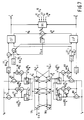
- Fig. 1 shows a functional discrete-time model of a system for transmitting data symbols a k at a symbol rate 1/T through a noisy dispersive channel CHN to a data receiver REC.
- the transmitted data signal a k is binary with a k ⁇ ⁇ -1, +1 ⁇ . This assumption is not meant to be restrictive.
- the invention is equally applicable to multilevel or complex-valued data signals, as encountered in e.g. digital voiceband communication systems.
- the channel CHN of Fig. 1 models the cascade of the actual continuous-time channel, a possible receiving filter and/or equalizer, and a synchronous sampling operation at the data rate 1/T.
- the nonnegative integer M is referred to as the memory length of the channel.
- the receiver REC in Fig. 1 operates on r k in order to produce decisions â k-D about a delayed version a k-D of a k , where D is a nonnegative integer that is referred to as the detection delay.
- FIG. 2 depicts a basic model of the likelihood calculations that are associated to any survivor s i k-1 in a receiver according to the above-mentioned prior art.
- a measure of accumulated likelihood j i k-1 is associated to the survivor s i k-1 .
- this measure of accumulated likelihood will henceforth be referred to as a metric for the sake of compactness.
- the components f T â ij k are generated by linear weighing networks LW ij that operate on the M most recent digits of s ij k , and can be recognized as hypothesized channel output samples that would result on moment k if noise ware absent and s ij k were transmitted.
- the metrics J ij k can be interpreted as accumulated Euclidean distances between the actual channel output signal r k and hypothesized channel output signals f T â ij k . As time proceeds, the detector seeks to minimize this distance across all considered survivors.
- the detector compares the metrics J ij k of the extended survivors for all i E ⁇ 0,...N-1 ⁇ and j E ⁇ 0,1 ⁇ , and makes a selection on this basis.
- the details of this selection depend on the precise type of Viterbi detector, and will not be described here in further detail as they are immaterial to the invention.
- the outputs of the linear weighing networks LW ij can only serve as hypothesized channel outputs in the absence of noise for channels CHN that do not introduce nonlinear ISI. For this reason Viterbi detectors that conform to Fig. 2 are intrinsically unable to handle nonlinear ISI.
- Fig. 3 is identical to Fig. 2 except for look-up tables LUT ij that replace the linear weighing networks LW ij .
- Each table is addressed by a total of M+1 binary data symbols and must therefore contain a total of 2 M+1 entries. Even for values of M as large as e.g. 10 this poses no instrumentational problems when use is made of currently available random access memories.
- This detector also distinguishes itself from Viterbi detectors according to the above-described prior art in that it can handle nonlinear ISI.
- the Viterbi detector of Mesiya et al. the ability to handle nonlinear ISI comes, in general, at the cost of a greatly increased complexity.
- various summations need to be performed per symbol interval T and survivor (see eq. (26) of said article by Mesiya et al. and the accompanying explanations), as opposted to the single look-up operation in the receiver according to the invention.
- Viterbi detector including those described in said article by Bergmans et al., several of the most recent bits of â ij k are known a priori. This enables further reductions in the size of each table.
- the new entries h'( a ij k ) are ideally improved estimates of f( a ij k ).
- LMS adaptation algorithm that forms the basis for the recursion of (9) can be found, for example, in an article by P.J. van Gerwen, N.A.M. Verhoecks and T.A.C.M. Claasen entitled "Design Considerations for a 144 kbit/s Digital Transmission Unit for the Local Telephone Network", IEEE J. Selected Areas in Commun., Vol. SAC-2, No.
- the data vector a k which by (1) underlies r k should coincide with the data vector â ij k of the table that is being updated. Among all possible data vectors â ij k , the one with greatest accumulated likelihood is most likely to satisfy this prerequisite.
- the selector signals d ij k of (11) are entirely based on information that is generated as an integral part of the detection process. For this reason they can be generated with a minimum of extra hardware.
- the adaptation constant ⁇ in (9) enables a tradeoff between speed of convergence of the tables and steady state excess mean-square error.
- ⁇ is usually chosen to be of the form 2 -W for some positive integer W, so that the multiplication by ⁇ in (9) amounts to a shift over W bit positions.
- a disadvantage of the configuration of Fig. 4 is that very recent estimated data symbols play a role in the adaptation process. By nature of Viterbi detection, these symbols are less reliable estimated of the transmitted data signal than the older digits that also form part of the maintained survivors. More specifically, even if a given survivor s ij k has greatest current likelihood, its most recent digits (e.g. â ij k and â ij k-1 ) may not coincide with the corresponding transmitted digits. Especially for functions f(.) with a weak dependence on these most recent transmitted digits this may in fact occur quite frequently. By (9) and (10) this would equally often cause erroneous table entries to be updated, a problem that may hamper or even preclude convergence of the table contents to the proper values.
- Fig. 5 A natural possibility to this end is outlined in Fig. 5.
- the six switches SW 0 0 ,...SW 1 2 of Fig. 5 are in the position "detect", detection proceeds exactly as in Fig. 4, with the look-up tables LUT ij addressed by the estimated data vectors â ij k .
- the switches are placed in the position "adapt".
- a delayed data vector b ⁇ ⁇ k i [â k-M-P i ,...,â k-P i ] addresses every look-up table LUT ij .
- the digits A i k-M-P ,..., â i k-P are for any i likely to be reliable estimates of the actually transmitted data symbols a k-M-P ,...,a k-P .
- the received signal r k is also delayed over P symbol intervals in order to form a delayed error signal which is used to update the look-up table LUT ij according to the LMS logarithm
- the data estimates used in this adaptation process are all relatively reliable, it is unnecessary in (14) to use selector signals to condition adaptation on current or past likelihood measures.
- FIG. 5 A disadvantage of the configuration of Fig. 5 is that each table is read out twice per symbol interval for calculation of error signals that play a role in detection and adaptation, respectively. Relative to Fig. 4, where these two functions are combined, this lowers the largest attainable data throughput. To overcome this problem it is possible to base adaptation on delayed versions of the error signals that were calculated for detection P symbol intervals earlier. This also makes it unnecessary to delay the received signal r k . A simplified version of this possibility will be described later.
- Fig. 6 shows a conceptual model of a two-state Viterbi detector with linear feedback as described in the aforementioned article by Bergmans et al..
- the four extended survivors s ij k for i,j ⁇ ⁇ 0,1 ⁇ are defined as in (5) and have metrics J ij k according to (6).
- Four linear weighing networks LW ij with i,j ⁇ ⁇ 0,1 ⁇ calculate the four possible weighted sums f T â ij k of eq. (6).
- the vecot f specifies the impulse response of the channel. This may be achieved, for example, with the help of adaptive techniques, as described in the aforementioned book by Proakis, chapter 6, pp. 410-412. Details of these techniques as applied in receivers of prior art are immaterial to the invention and therefore not discussed or shown here.
- â k-D is arbitrarily chosen to be the detector output â k-D .
- a disadvantage of the detector of Fig. 6 is that the metric values j i k are, by (6) and (15), a non-decreasing function of time in the usual case that the function G(.) is nonnegative definite. This may cause problems of overflow in a digital implementation of the detector. From (15) it can be noted that only differences between metrics play a role in the selection of new survivors. This observation may be used to re-normalize metric values in such a way that they are no longer a non-decreasing function of time.
- compare-select unit CS j produces an output signal Q j k according to eq.
- two shift registers SR0 and SR1 store the digits [â 0 k-D ,...â 0 k-2 ] and [â 1 k-D ,...,â 1 k-2 ] of the survivors s 0 k-1 and s 1 k-1 , respectively.
- shift register SR1 happens to have a significantly smaller propagation delay than shift register SR0, then a PARALLEL LOAD operation on SR0 may cause one or more digits of the new survivor s 1 k rather than the desired ones of the old survivor SR 0 k-1 to be loaded into SR1.
- shift register SR0 if the propagation delay of shift register SR0 is significantly smaller than that of SR1, then a LOAD PARALLEL operation on shift register SR1 may cause one or more digits of the new survivor s 0 k rather than the desired ones of the old survivor s 0 k-1 to be loaded into SR1. Both possibilities are clearly undesirable. To avoid this problem, it is possible in a practical implementation of the receiver of Fig. 7 to choose shift registers SR1 and SR0 with well-matched propagation delays, or to latch the cross-couplings between both shift registers. As the diagram of Fig. 7 is merely meant to provide a conceptual model of a receiver according to the invention, possibilities to avoid this implementation-level problem will not be elucidated here in any further detail.
- the look-up tables LUT ij with i,j ⁇ ⁇ 0,1 ⁇ are addressed by the digits [â i k-M ,..., â i k-2 ] of survivor s i k-1 .
- these digits coincide with the corresponding digits of the address vectors a ij k .
- each table can be 4 times smaller in size than for an address vector of the "full" length M+1.
- the adaption mechanism for the look-up tables LUT ij is identical to that of Fig. 4 and is therefore not explained in further detail.
- the selector signals d ij k are such that only the table that corresponds to the most likely extended survivor is updated.
- selector signals are produced by a selector unit SEL that operates, for example, on the signals Q k , d 0 k and d 1 k according to the following truth table: Q k d 0 k d 1 k d 00 k d 01 k d 10 k d 11 k ⁇ 0 0,1 1 0 0 0 1 ⁇ 0 0,1 0 0 0 1 0 >0 1 0,1 0 1 0 0 >0 0 0,1 1 0 0 0 0 0 0 0 0 0 0
- any positive value of Q k indicates that the new survivor s 0 k is more likely than its counterpart s 1 k , and vice versa for a negative value of Q k .
- the signal d 0 k can be used to this end, as it specifies, by eq. (22), exactly which of these two extended survivors forms s 0 k .
- the signal d 1 k specifies which of the two selector signals d 01 k and d 11 k is to be 1, while the other two selector signals are zero.
- the new value Q k is determined from the signals Q 1 k and Q 0 k according to eq. (20) by means of a summator, while a delay unit stores Q k for use during the next symbol interval.
- the oldest digit â 1 k-D serves as the output â k-D of the receiver, as in Fig. 6.
- further aspects of the receiver are not elaborated here as they are either sufficiently self-evident or sufficiently similar to aspects that were discussed before.
- the receiver of Fig. 7 is attractive in that it combines a complexity no greater than that of its linear counterpart of Fig. 6 with the ability to handle any form of linear or nonlinear ISI. Together with the receiver of Fig. 6, it shares the disadvantage that implementation may become difficult at very high data rates, as encountered in e.g. digital storage of video signals.
- One cause of this difficulty is that the formation of the signals G(e ij k ) in Fig. 7 requires a table look-up operation, a subtraction and application of the function G, which together may require more time than is permissible.
- Two adders serve to form error signals e 0ij k and e 1ij k by subtracting h 0ij and h 1ij from r k . Subsequent application of the function G(.) yields signals G(e 0ij k ) and G(e 0ij k ), one of which corresponds with the signal G(e ij k ) that is to be formed.
- This feedback operation is the counterpart of the linear feedback operation that takes place in a more implicit manner in the conventional receiver of Fig. 7, as explained, for example, in the aforementioned article by Bergmans et al..
- the configuration of Fig. 8 includes a simplified version of the mechanism of Fig. 5 for adaptation of the counters C 0ij and C 1ij on the basis of delayed digits â i k-M-P ,...,â i k-P .
- the mechanism of Fig. 5 is preferable over the one of Figs. 4 and Fig. 7 in that it lowers convergence problems for functions f( a k ) with a weak dependence on the most recent digits of a k , such as a k and a k-1 .
- Said simplification stems from a sign operation that is performed on the error signals e 0ij k and e 1ij k to obtain one-bit error signals that are conveniently handled with digital circuitry.
- a switch SW e with a feedback function similar to that of SW g is controlled by â i k-2 to obtain the one-bit and undelayed counterpart sgn of the error signal of eq. (13).
- This signal sgn is applied to a binary shift register that introduces a delay of P symbol intervals T.
- the delayed error signal sgn serves to update the contents of the counters according to the sign algorithm Details about this simplified version of the LMS algorithm can be found, for example, in an article by N. Holte and S.
- d 1ij k is a binary selector signal to be described, not to be confused with the signal d ij k of Fig. 7.
- q is the quantization step size that corresponds to an increment or decrement of counter C 1ij by one unit.
- the delayed error signal sgn is by (1) a function of the delayed data vector a k-P .
- Alternative rules in which both vectors b ⁇ 0 k and b ⁇ 1 k are used for the formation of essentially equivalent selector signal signals are, of course, equally suitable but are not described here for the sake of brevity.
- Fig. 8 In the configuration of Fig. 8, the signals d 1ij k and sgn are connected to the COUNT ENABLE and UP/DOWN inputs of counters C 1ij in order to realize the iteration of (24). Depending on such implementation details as the type of counters used, slight modifications of the configuration of Fig. 8 may be needed to realize the iteration of eq. (24) in a convenient manner. In this respect Fig. 8 is merely illustrative, and is not meant to restrict in any sense the use of the sign-algorithm as described above.
- Fig. 8 can be easily modified for use of the LMS rather than sign-algorithm by omitting the Sign-operations in Fig. 1.
- the counters of Fig. 8 should then be replaced by digital accumulators that store h 1ij k and can be updated in steps q. that may assume a multitude of sizes.
- Intermediate forms of the LMS and sign algorithms arise when such an accumulator is used in combination with a multi-bit quantizer instead of the sign operation in Fig. 8.
- u or q can be variable rather than fixed. For example, for rapid convergence it is attractive to start adaptation with a relatively large value of u or q. Subsequently, u or q may be decreased gradually or step-wise to a value that is appropriate for small steady-state adaptation errors.
- Fig. 8 is meant to be illustrative rather than restrictive.
- Fig. 9 depicts a model of a two-state Viterbi detector according to the invention in which the precomputation units of Fig. 8 are applied.
- the detector of Fig. 9 rather distinguishes itself from the one of Fig. 7 in that it employs a faster method of calculating Q k .
- calculation of Q k can not start before the selection process in compare/select units CS0 and CS1 is completed.
- these actions occur largely in parallel.
- these 4 possible values are calculated with the help of 4 summators, and concurrently the comparators S0 and S1 produce the logical signals d 0 k and d 1 k of eq. (21).
- the actual value of Q k is merely selected from the 4 possible values in a selection circuit S q under control of d 0 k and d 1 k . From eqs. (18), (20) and (22) it may be seen that these two bits provide exactly enough information for this selection. As selection is usually a faster process than addition, the configuration for calculating Q k in Fig. 9 may be applicable at higher data rates than the one of Fig. 7, though at the cost of additional hardware, notably 3 additional adders.
- the complete receiver according to Figs. 8 and 9 may be implemented with approximately 80 digital integrated circuits from the standard ECL 100K series as described, for example, in the "F100K ECL data book", Fairchild Camera and Instrument Corporation, Mountain View, California, 1982.
- internal signals of the receiver are represented with a word-length of at most 6 bits.
- the attainable data rate amounts to approximately 50 Mbit/s. Even for digital video storage applications this may be an appropriate value.
- the nonlinearities arise from a systematic difference in the length of the pits and lands that represent runs of zeros and ones.
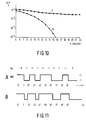
- the curves of Fig. 10 pertain to a situation with severe nonlinear ISI, in which systematic errors in the writing process cause runs of zeros and ones to be T/2 seconds shorter and longer than their nominal value, respectively.
- Fig. 11 This situation is illustrated in Fig. 11.
- the upper trace A depicts the NRZ waveform that is applied to the channel
- the lower trace B depicts the corresponding pattern of pits and lands that is assumed to be recorded on the optical medium.
- the systematic difference in the lengths of pits and lands manifests itself in the replayed signal as severe nonlinear ISI.
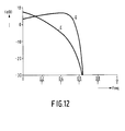
- the replayed signal is taken to contain linear ISI as a result of the channel bandwidth limitations that are reflected in Fig. 12.
- the curve that is labeled C in Fig. 12 depicts the transfer characteristic of the linear part of the channel.
- Fig. 10 confirms the superiority of the receiver according to the invention (curve b.) over its conventional counterpart (curve a.) in dealing with nonlinear ISI. While the former receiver is unable to achieve useful performance levels even at very high signal-to-noise ratio's, the latter one already achieves bit error rates of around 10 ⁇ 4 for signal-to-noise ratio's of about 16 dB. Additional simulations reveal that this represents a loss of only 3 to 4 dB with respect to a corresponding situation without nonlinearities. Thus a receiver according to the invention may provide an attractive degree of insensitivity to nonlinear ISI, unlike its predecessors of prior art.
Description
- The invention relates to a system according to the preamble of
claim 1. - Such a system is know from an article by G.D. Forney, Jr. entitled "Maximum-Likelihood Sequence Estimations of Digital Sequence Estimation of digital Sequences in the Presence of Intersymbol Interference"", IEEE Trans. Inform. Theory, Vol. IT-18, No. 3, pp. 363-378, May 1972.
- In the forthcoming decades, digital optical storage is expected to find widespread for storage of computer data as well as of digitized audio and video signals. In systems of this type, binary information is stored as a sequence of this type, binary information is stored as a sequence of pits and lands in an optical medium. Imperfections in writing process may cause pits and lands to differ in shape or length. In the replay process, this asymmetry manifests itself in the form of nonlinear intersymbols interference (ISI). This disturbance comes on top of linear ISI that arises due, for example to limitations of optical resolution, and to noise generated in e.g. laser diodes and preamplifiers. Conventional reception techniques are, in general, only able to deal with the latter two imperfections. This even applies for the most powerful variety, whose representatives are commonly referred to as Viterbi detectors. Conventional Viterbi detectors form an estimate of the most likely transmitted data sequence, assuming that only linear ISI and noise are present. To this end, they maintain a list of candidate data sequences that are referred to as survivors. These survivors are recursively extended, and a selection process takes place on the basis of likelihood measures that are calculated for each survivor by comparing the actual channel output signal with a hypothesized output signal that would result if noise were absent and the concerned survivor would have been transmitted. The aforementioned means to form these hypothesized channel output signals conventionally consist of linear weighing networks that operate on a given number of the most recent symbols of concerned survivors.
- Basic elements of this detection process are described in more detail, for example, in the aforementioned article by Forney. The conventional Viterbi detector developed in this article has the disadvantage that its complexity grows rapidly to unmanageable proportions as channel memory lengths increase. To overcome this problem, various simplified versions of the conventional Viterbi detector have been developed in recent years, as exemplified, for example, by an article by J.W.M. Bergmans, S.A. Rajput and F.A. M. van de Laar entitled "On the Use of Decision Feedback for Simplifying the Viterbi Detector", Philips J. Res., Vol. 42, No. 4, pp. 399-428, 1987. Partly as a consequence of these efforts towards simplification, conventional Viterbi detectors now find application in such areas as voiceband modems and digital magnetic recording. To date, however, nonlinear ISI has discouraged their use in optical storage.
- An article by M.F. Mesiya, P.J. McLane, and L.L. Campbell entitled "Maximum Likelihood Sequences Transmitted over Nonlinear Channels", IEEE Trans. Commun., Vol COM-25, No. 7, pp. 633-643, July 1977, puts forth a novel type of Viterbi detector that distinguishes itself from conventional Viterbi detectors in that it can handle nonlinear ISI. Unfortunately this ability comes, in general, at the cost of a greatly increased complexity.
- US 4,015,238 discloses a Viterbi decoder for decoding a signal being encoded using a convolutional code. Said decoder is only arranged for coping with noise, and is not intended for dealing with intersymbol interference.
- It is the object of the present invention to provide a novel category of Viterbi detectors with the ability to handle a mixture of linear and nonlinear ISI and noise, and with a complexity comparable to that of Viterbi detectors of the abovementioned prior art.
- To this end the receiver is arranged according to the characterizing part of
claim 1. - As look-up tables are ideally suited to store nonlinear input-output relations, they can account for any nonlinearity of the channel. Furthermore, because they can account for any nonlinearity of the channel. Furthermore, because they all operate on digital data symbols, these look-up tables are often more conveniently implemented in digital technology than the linear weighing networks in receivers of the above-mentioned prior art. In this way the ability to handle nonlinear ISI is generally accompanied by a decreased receiver complexity.
- An especially simple version of the receiver according to the invention has only two candidate data sequences, which are recursively updated on the basis of a likelihood measure that is representative for the difference of a function of the likelihoods of both candidate data sequences, and that is determined with the help of means for estimating hypothesized channel outputs in the absence of noise. To facilitate its application at high data rates, this receiver is further characterized in that said likelihood measure is determined by selection among precomputed candidate values of said likelihood measure.
- A special version of the receiver according to the invention in which all look-up tables have only one entry is characterized in that said look-up tables take the form of registers that store hypothesized channel output symbols in the absence of noise.
- In practice, the precise characteristics of a storage channel usually vary dynamically around a nominal average as a result of e.g. mechanical vibrations and tracking or defocussing errors. As a rule, the performance of Viterbi detectors degrades rapidly when the actual characteristics of the channel come to differ from the ones reflected in said means for estimating hypothesized channel output signals in the absence of noise. The detrimental effects of this channel-receiver mismatch are illustrated, for example, in an article by K.A. Schouhamer Immink entitled "Coding Methods for High-Density Optical Recording", Philips J. Res., Vol. 41, No. 4, pp. 410-430, 1986.
- It is a further object of the invention to reduce performance degradation due to said channel-receiver mismatch.
- As a first means to this end, the receiver is further characterized in that each look-up table is adapted under the control of digits of said candidate data sequences, in response to an error signal that is representative for the difference of the channel output signal and the output signal of said look-up table.
- As a second means to this end, the receiver according to the invention is further characterized in that each look-up table is adapted in response to an error signal that is representative for the difference of a delayed version of the channel output signal and the output signal of said look-up table when addressed by one or more delayed digits of said candidate data sequences.
- By making the look-up tables adaptive, they attain the ability to track variations of the channel characteristics. This greatly reduces said channel-receiver mismatch.
- For the special case that look-up tables take the form of registers that store hypothesized channel output symbols in the absence of noise, an adaptive version of the receiver according to the invention is further characterized in that each register takes the form of a digital counter that is adapted, under the control of one or more delayed digits of said candidate data sequences, in response to an error signal that is representative for the difference of a delayed version of the channel output signal and the contents of said counter.
- An especially simple version of a receiver according to the invention is further characterized in that each likelihood measure is representative for an accumulated version of a function that essentially equals the modulus of the difference of the actual channel output signal and a hypothesized channel output signal in the absence of noise. To facilitate its application at high data rates, this receiver is further characterized in that said function is determined by selection among precomputed candidate values of said function.
- Backgrounds and embodiments of the invention and their advantages will now be further explained with reference to the drawing, in which
- Fig. 1 shows a functional discrete-time model of a system for transmitting data symbols ak at a
symbol rate 1/T through a noisy dispersive channel CHN to a data receiver REC. - Fig. 2 shows a conceptual model of the computations that are performed for any survivor in a receiver of the above-mentioned prior art to guide the selection process;
- Fig. 3 shows a conceptual model of the computations that are performed for any survivor in a receiver according to the invention to guide the selection process;
- Fig. 4 shows an adaptive version of the conceptual model of Fig. 3;
- Fig. 5 shows an adaptive version of the conceptual model of Fig. 3 in which adaptation is based on delayed digits of the survivor.
- Fig. 6 shows a model of a 2-state Viterbi detector with linear feedback according to the above-mentioned prior art;
- Fig. 7 shows a conceptual model of an adaptive 2-state Viterbi detector with nonlinear feedback according to the invention;
- Fig. 8 shows a conceptual model of an adaptive precomputation unit for a receiver according to the invention;
- Fig. 9 shows a conceptual model of an adaptive 2-state Viterbi detector with nonlinear feedback according to the invention that uses adaptive pre-computation units according to Fig. 8;
- Fig. 10 shows bit error characteristics that were obtained by simulation for a conventional receiver according to Fig. 6 and a receiver according to the invention that conforms to Figs. 8 and 9;
- Fig. 11 illustrates the nonlinearity mechanism in the system that underlies the simulation results of Fig. 10;
- Fig. 12 shows the transfer characteristics of the linear part of the recording channel that underlies the simulation results of Fig. 10.
- In all figures, corresponding elements are denoted by the same symbols.
- In the following description a discrete-time modelling of the transmission system and the arrangement is used, as the general notion of the invention can be presented in the most simple way with reference to such a modelling. This does not lead to a loss of generality as the present modelling can be derived unambiguously from the parameters of the actual continuous-time system as described, for example, in the book entitled "Digital Communications", by J.G. Proakis, McGraw-Hill, New York, 1983,
Chapter 6, and especially Section 6.3, pp. 351-357. - Fig. 1 shows a functional discrete-time model of a system for transmitting data symbols ak at a
symbol rate 1/T through a noisy dispersive channel CHN to a data receiver REC. To simplify the exposition, it will henceforth be assumed that the transmitted data signal ak is binary with ak ∈ {-1, +1}. This assumption is not meant to be restrictive. With self-evident modifications, the invention is equally applicable to multilevel or complex-valued data signals, as encountered in e.g. digital voiceband communication systems. The channel CHN of Fig. 1 models the cascade of the actual continuous-time channel, a possible receiving filter and/or equalizer, and a synchronous sampling operation at thedata rate 1/T. The discrete-time output signal rk of channel CHN can be described as


- Conventional receivers REC are, in general, not able to handle nonlinear ISI. This applies even for the most powerful variety of conventional receivers, whose representatives are generally known as Viterbi detectors. These detectors form an estimate of the most likely transmitted data sequence, assuming that only linear ISI and noise are present. To this end, they maintain at any instant k-1 a list with a given number N of candidate data vectors


- In Fig. 2, a measure of accumulated likelihood j


- Associated to the extended survivors s


- To update its list of survivors, the detector compares the metrics J

- Because of their linear form, the outputs of the linear weighing networks LWij can only serve as hypothesized channel outputs in the absence of noise for channels CHN that do not introduce nonlinear ISI. For this reason Viterbi detectors that conform to Fig. 2 are intrinsically unable to handle nonlinear ISI.
- Central to the invention is the observation that the linear weighing networks LWij operate on vectors â


- In Fig. 3, the tables LUTi1 and LUTi0 are addressed by vectors â


- Prior knowledge about the channel characteristics may be used to identify the function f(.). The tables LUTij can then be filled with appropriate values on the basis of condition (8). Unfortunately, the precise characteristics of a storage channel usually vary dynamically as a result of e.g. mechanical vibrations and tracking or defocussing errors. The function f(.) then fluctuates in time, and it becomes impossible for a time-invariant function h(.) as stored in the look-up tables LUTij of Fig. 3 to fully match f(.). For the particular case of linear functions f(.) and h(.), the detrimental effects of such a channel-receiver mismatch were studied, for example, in said article by Schouhamer Immink. In this article, it is illustrated that even small mismatches may result in serious performance degradations, especially at high information densities. To avoid such degradations, it is desirable for the function h(.) to track any variations of f(.). This is possible by making the look-up tables LUTij adaptive, as illustrated in Fig. 4.
- In Fig. 4, the function h(.) as stored in the look-up tables LUTij is updated recursively according to


Thus at any instant k at most one of the tables is updated. It can be observed that the selector signals d
form 2-W for some positive integer W, so that the multiplication by µ in (9) amounts to a shift over W bit positions. For the sake of compactness, these and other aspects of the LMS algorithm and its implementation are not described here in further detail, as they are well documented in the literature, see e.g. said article by van Gerwen et at.. A detailed description of an adaptive receiver according to the invention and based on a simplified version of the LMS algorithm will be given later. - In practice it is advisable to initialize the table entries h(â

- A disadvantage of the configuration of Fig. 4 is that very recent estimated data symbols play a role in the adaptation process. By nature of Viterbi detection, these symbols are less reliable estimated of the transmitted data signal than the older digits that also form part of the maintained survivors. More specifically, even if a given survivor s


- To overcome this problem it is necessary to base adaptation on more reliable and hence delayed estimates of the transmitted data signal. A natural possibility to this end is outlined in Fig. 5. When the six
switches SW 
SW 


- A disadvantage of the configuration of Fig. 5 is that each table is read out twice per symbol interval for calculation of error signals that play a role in detection and adaptation, respectively. Relative to Fig. 4, where these two functions are combined, this lowers the largest attainable data throughput. To overcome this problem it is possible to base adaptation on delayed versions of the error signals that were calculated for detection P symbol intervals earlier. This also makes it unnecessary to delay the received signal rk. A simplified version of this possibility will be described later.
- To exemplify the preceding notions, two versions of a two-state Viterbi detector with nonlinear feedback according to the invention will now be developed. To facilitate the explanation, a related Viterbi detector of prior art will be described first.
- Fig. 6 shows a conceptual model of a two-state Viterbi detector with linear feedback as described in the aforementioned article by Bergmans et al.. This detector has two survivors s


chapter 6, pp. 410-412. Details of these techniques as applied in receivers of prior art are immaterial to the invention and therefore not discussed or shown here. - Among the extended survivors s


- For any Viterbi detector, it is desirable to have a detection delay D much greater than the channel memory length M, as explained, for example, in the aforementioned article by Forney. In this case, the oldest digits âk-D and
â 
â 
â 
- Further backgrounds and clarifications of the detection process of Fig. 6 are not expounded here as they are described in detail in said article by Bergmans et al..
- A disadvantage of the detector of Fig. 6 is that the metric values j


- In the receiver of Fig. 7, two compare-select units CS⁰ and CS¹ are used to control the selection process of eq. (18) for j=0 and j=1, respectively. Based on input signals Qk+G[e


- To implement this selection process, two shift registers SR⁰ and SR¹ store the digits [
â 

â 


- For shift register SR⁰, a selector signal d


oldest digit â 


oldest digit â 


- For the sake of completeness it is necessary to mention a potential problem that may occur in a direct implementation of the shift register configuration of Fig. 7 as a consequence of poor matching of the propagation delays of both shift registers. If shift register SR¹ happens to have a significantly smaller propagation delay than shift register SR⁰, then a PARALLEL LOAD operation on SR⁰ may cause one or more digits of the new survivor s


- In Fig. 7, the look-up tables LUTij with i,j ∈ {0,1} are addressed by the digits [â


- The adaption mechanism for the look-up tables LUTij is identical to that of Fig. 4 and is therefore not explained in further detail. At any instant k, the selector signals d


Qk d 
d 
d 
d 
d 
d 
<0 0,1 1 0 0 0 1 <0 0,1 0 0 0 1 0 >0 1 0,1 0 1 0 0 >0 0 0,1 1 0 0 0 - To explain this table, it can be noted from (16) and the accompanying explanation that any positive value of Qk indicates that the new survivor s


d 
- An attractive choice for the function G(.) in Fig. 7 is G(x)= |x| for all x ∈ R, since this function can be easily realized or approximated with digital circuitry. Simulations for the receiver of Fig. 7 reveal that in many cases this choice yields performances that are essentially equivalent to those for the usual function G(x)=x for all x ∈ R, which is comparatively difficult to realize or approximate with digital circuitry.
- With respect to the receiver of Fig. 7, it remains to mention that the new value Qk is determined from the signals Q


oldest digit â 
- The receiver of Fig. 7 is attractive in that it combines a complexity no greater than that of its linear counterpart of Fig. 6 with the ability to handle any form of linear or nonlinear ISI. Together with the receiver of Fig. 6, it shares the disadvantage that implementation may become difficult at very high data rates, as encountered in e.g. digital storage of video signals. One cause of this difficulty is that the formation of the signals G(e

- To explain the technique, it is noted from Fig. 7 that the signals G(e


- In the system of Fig. 8, two digital up/down counters C0ij and C1ij replace the wM-1=2 table entries of table LUTij in Fig. 7. More specifically, these counters account for extended survivors with data vectors â

- Two adders serve to form error signals e


- In the circuit of Fig. 8, the digit â


- The configuration of Fig. 8 includes a simplified version of the mechanism of Fig. 5 for adaptation of the counters C0ij and C1ij on the basis of delayed digits â


 of the error signal
 of eq. (13). This signal sgn
 is applied to a binary shift register that introduces a delay of P symbol intervals T. The delayed error signal sgn
 serves to update the contents of the counters according to the sign algorithm


- Because of the delay over P symbol intervals T, the delayed error signal sgnis by (1) a function of the delayed data vector a k-P. As explained in the aforementioned article by Holte and Stueflotten, for a proper operation of the sign algorithm of (24), only that counter C1ij should be updated for which [I(1),I(i),I(j)]T=a k-P. When P is taken sufficiently large, the vectors b̂


- In the configuration of Fig. 8, the signals d
 are connected to the COUNT ENABLE and UP/DOWN inputs of counters C1ij in order to realize the iteration of (24). Depending on such implementation details as the type of counters used, slight modifications of the configuration of Fig. 8 may be needed to realize the iteration of eq. (24) in a convenient manner. In this respect Fig. 8 is merely illustrative, and is not meant to restrict in any sense the use of the sign-algorithm as described above.
- For the sake of completeness it is necessary to mention that the configuration of Fig. 8 can be easily modified for use of the LMS rather than sign-algorithm by omitting the Sign-operations in Fig. 1. The counters of Fig. 8 should then be replaced by digital accumulators that store h
 that may assume a multitude of sizes. Intermediate forms of the LMS and sign algorithms arise when such an accumulator is used in combination with a multi-bit quantizer instead of the sign operation in Fig. 8. Also, u or q can be variable rather than fixed. For example, for rapid convergence it is attractive to start adaptation with a relatively large value of u or q. Subsequently, u or q may be decreased gradually or step-wise to a value that is appropriate for small steady-state adaptation errors. Thus, with respect to the precise adaptation algorithm used, Fig. 8 is meant to be illustrative rather than restrictive.
- It is straightforward to generalize the configuration of Fig. 8 to channel memory lengths M greater than 2. In this case, the M-1 digits â


 under control of the M-1 digits â


- Application of adaptive precomputation units like the one of Fig. 8 facilitates the attainment of high data rates. Fig. 9 depicts a model of a two-state Viterbi detector according to the invention in which the precomputation units of Fig. 8 are applied. The detector of Fig. 9 rather distinguishes itself from the one of Fig. 7 in that it employs a faster method of calculating Qk. In Fig. 7, calculation of Qk can not start before the selection process in compare/select units CS⁰ and CS¹ is completed. In Fig. 9, on the other hand, these actions occur largely in parallel. To explain this parallelism, it is noted from expression (18) that


- The selector signals d

digits â 


- For illustrative purposes it is mentioned here that the complete receiver according to Figs. 8 and 9 may be implemented with approximately 80 digital integrated circuits from the standard ECL 100K series as described, for example, in the "F100K ECL data book", Fairchild Camera and Instrument Corporation, Mountain View, California, 1982. In this implementation, internal signals of the receiver are represented with a word-length of at most 6 bits. The attainable data rate amounts to approximately 50 Mbit/s. Even for digital video storage applications this may be an appropriate value.
- To illustrate the merits of receivers according to the invention, Fig. 10 depicts bit error characteristics that were obtained by simulation for a receiver of prior art conforming to Fig. 7 (curve a.) and one according to the invention that conforms to Figs. 8 and 9 (curve b.). Both receivers operate on the output of an equalized optical recording channel with nonlinear ISI and a memory length M=2, to which random (NRZ) data is applied. The nonlinearities arise from a systematic difference in the length of the pits and lands that represent runs of zeros and ones. The curves of Fig. 10 pertain to a situation with severe nonlinear ISI, in which systematic errors in the writing process cause runs of zeros and ones to be T/2 seconds shorter and longer than their nominal value, respectively. This situation is illustrated in Fig. 11. In this Figure, the upper trace A depicts the NRZ waveform that is applied to the channel, while the lower trace B depicts the corresponding pattern of pits and lands that is assumed to be recorded on the optical medium. The systematic difference in the lengths of pits and lands manifests itself in the replayed signal as severe nonlinear ISI. In addition to this nonlinear ISI, the replayed signal is taken to contain linear ISI as a result of the channel bandwidth limitations that are reflected in Fig. 12. The curve that is labeled C in Fig. 12 depicts the transfer characteristic of the linear part of the channel. The loss of around 20 dB at the
Nyquist frequency 1/(2T) is characteristic for recording at high information densities, and results in severe linear ISI in the replay signal. As both simulated receivers are only able to handle the comparatively small memory length M=2, an equalizer operating on the replayed signal is used to shorten the memory length of the channel into a memory length M of approximately 2 symbol intervals. Techniques for designing this equalizer are not discussed here as they are well described in the literature, see e.g. an article by D.D. Falconer and F.R. Magee, Jr Entitled "Adaptive Channel Memory Truncation for Maximum Likelihood Sequence Estimation", Bell Syst. Tech. J., Vol. 52, pp. 1541-1562, Nov. 1973. The amplitude-frequency characteristics of the equalizer are depicted in the curve that is labeled D in Fig. 12. Both the equalizer and the linear part of the channel have linear phase characteristics. A third disturbance, white Gaussian noise that models possible noise sources in the system, is added to the output signal of the channel, i.e. just before the input of the equalizer. - Fig. 10 confirms the superiority of the receiver according to the invention (curve b.) over its conventional counterpart (curve a.) in dealing with nonlinear ISI. While the former receiver is unable to achieve useful performance levels even at very high signal-to-noise ratio's, the latter one already achieves bit error rates of around 10⁻⁴ for signal-to-noise ratio's of about 16 dB. Additional simulations reveal that this represents a loss of only 3 to 4 dB with respect to a corresponding situation without nonlinearities. Thus a receiver according to the invention may provide an attractive degree of insensitivity to nonlinear ISI, unlike its predecessors of prior art.
- For the sake of completeness, it is mentioned that the performance of the conventional receiver can be improved with respect to curve a. in Fig. 10 by preceding it by a DC-blocking circuit. This possibility stems from the fact that a major effect of the nonlinearity mechanism of Fig. 11 is a shift of DC-level. This effect is easily dealt with by conventional means, such as a DC-blocking circuit. For nonlinearity mechanisms with a more complicated nature than the one of Fig. 11, however, such a circuit may prove to be largely ineffective, whereas the receiver according to the invention is effective irrespective of the precise nonlinearity mechanism.
Claims (9)
- System for transmitting a data signal at a symbol rate 1/T through a noisy dispersive channel (CHN) to a data receiver (REC); said channel (CHN) introducing intersymbol interference and noise into the transmitted data signal, said receiver (REC) comprising means for estimating the most likely sequence of transmitted data symbols by keeping track of candidate sequences (S) and associated likelihood measures (I), means for determining said likelihood measures by comparison of the actual channel output signal (rk) with a hypothetical channel output signal that would have been received if noise was absent and said candidate data sequence would have been transmitted, and means for estimating said hypothetical channel output signal from said candidate sequence, characterized in that said means for estimating said hypothetical channel output signals comprise one or more look-up tables storing said possible hypothetical channel output signals corresponding to said candidate data sequences.
- System according to claim 1, characterized in that the means for estimating the most likely sequence of transmitted data symbols is arranged for keeping track of two candidate sequences (S¹, S°) and a difference likelihood measure (Qk) that is representative for the difference of a function of the likelihoods of both candidate data sequences.
- System according to claim 2, further characterized in that said difference likelihood measure (Qk) is determined by selection among precomputed candidate values of said likelihood measure.
- System according to claim 1, 2 or 3, further characterized in that said look-up tables (LUT) take the form of registers that store hypothesized channel output symbols in the absence of noise.
- System according to claim 1, 2 3, or 4 further characterized in that each look-up table (LUT) is adapted under the control of digits of said candidate data sequences, in response to an error signal (ek) that is representative for the difference of the channel output signal and the output signal of said look-up table.
- System according to claim 1, 2 or 3, further characterized in that each look-up table (LUT) is adapted in response to an error signal (ek') that is representative for the difference of a delayed version of the channel output signal and the output signal of said look-up table (LUT) when addressed by one of more delayed digits of said candidate data sequences.
- System according to claim 4, further characterized in that each register takes the form of a digital counter (C) that is adapted under the control of one or more delayed digits of said candidate data sequences, in response to an error signal that is representative for the difference of a delayed version of the channel output signal and the contents of said counter (C).
- System according to claims 1, 2, 3, 4, 5, 6 or 7, further characterized in that each likelihood measure is representative for an accumulated version of a function that essentially equals the modulus of the difference of the actual channel output signal and a hypothesized channel output signal in the absence of noise.
- System according to claim 8, further characterized in that said function is determined by selection among precomputed candidate values G(lk) of said function.
Applications Claiming Priority (2)
| Application Number | Priority Date | Filing Date | Title |
|---|---|---|---|
| JP1160756A JP2960436B2 (en) | 1989-06-26 | 1989-06-26 | Receiver for nonlinear data transmission system |
| JP160756/89 | 1989-06-26 |
Publications (3)
| Publication Number | Publication Date |
|---|---|
| EP0405662A2 EP0405662A2 (en) | 1991-01-02 |
| EP0405662A3 EP0405662A3 (en) | 1992-02-26 |
| EP0405662B1 true EP0405662B1 (en) | 1996-02-21 |
Family
ID=15721788
Family Applications (1)
| Application Number | Title | Priority Date | Filing Date |
|---|---|---|---|
| EP90201631A Expired - Lifetime EP0405662B1 (en) | 1989-06-26 | 1990-06-21 | Receiver for data transmission system with nonlinearities |
Country Status (6)
| Country | Link |
|---|---|
| US (1) | US5131011A (en) |
| EP (1) | EP0405662B1 (en) |
| JP (1) | JP2960436B2 (en) |
| KR (1) | KR0152662B1 (en) |
| CA (1) | CA2019659C (en) |
| DE (1) | DE69025433T2 (en) |
Families Citing this family (35)
| Publication number | Priority date | Publication date | Assignee | Title |
|---|---|---|---|---|
| GB9105101D0 (en) * | 1991-03-11 | 1991-04-24 | British Telecomm | Error burst detection |
| DE69223438T2 (en) * | 1991-04-24 | 1998-06-04 | Koninkl Philips Electronics Nv | Scan clock recovery for receivers using Viterbi processing |
| MY108838A (en) * | 1992-07-03 | 1996-11-30 | Koninklijke Philips Electronics Nv | Adaptive viterbi detector |
| US5408503A (en) * | 1992-07-03 | 1995-04-18 | U.S. Philips Corporation | Adaptive viterbi detector |
| US5463654A (en) * | 1992-08-03 | 1995-10-31 | U.S. Philips Corporation | Transmission system with increased sampling rate detection |
| JPH0677767A (en) * | 1992-08-26 | 1994-03-18 | Sony Corp | Non-linear canceler |
| US5430744A (en) * | 1993-09-30 | 1995-07-04 | International Business Machines Corporation | Method and means for detecting partial response waveforms using a modified dynamic programming heuristic |
| FI107420B (en) * | 1994-04-18 | 2001-07-31 | Nokia Networks Oy | Reception procedure and recipients |
| US5542458A (en) * | 1994-08-22 | 1996-08-06 | Gilbarco Inc. | Vapor recovery system for a fuel delivery system |
| US5557645A (en) * | 1994-09-14 | 1996-09-17 | Ericsson-Ge Mobile Communications Inc. | Channel-independent equalizer device |
| US6393598B1 (en) | 1995-04-20 | 2002-05-21 | Seagate Technology Llc | Branch metric compensation for digital sequence detection |
| US6424685B1 (en) * | 1997-11-03 | 2002-07-23 | Harris Corporation | Polar computation of branch metrics for TCM |
| US6381271B1 (en) | 1998-08-17 | 2002-04-30 | Telefonaktiebolaget Lm Ericsson (Publ) | Low complexity decision feedback sequence estimation |
| US7099410B1 (en) | 1999-01-26 | 2006-08-29 | Ericsson Inc. | Reduced complexity MLSE equalizer for M-ary modulated signals |
| US6928161B1 (en) * | 2000-05-31 | 2005-08-09 | Intel Corporation | Echo cancellation apparatus, systems, and methods |
| US7006800B1 (en) * | 2003-06-05 | 2006-02-28 | National Semiconductor Corporation | Signal-to-noise ratio (SNR) estimator in wireless fading channels |
| JP2005166221A (en) * | 2003-12-05 | 2005-06-23 | Canon Inc | Information reproducing method and apparatus |
| US7653154B2 (en) * | 2004-05-25 | 2010-01-26 | Agere Systems Inc. | Method and apparatus for precomputation and pipelined selection of intersymbol interference estimates in a reduced-state Viterbi detector |
| KR100791568B1 (en) * | 2007-03-26 | 2008-01-03 | 전태구 | Compression type fire extinguisher |
| JP4973939B2 (en) * | 2007-10-10 | 2012-07-11 | ソニー株式会社 | Reception device, reception method, information processing device, information processing method, and program |
| US8225252B2 (en) * | 2010-06-25 | 2012-07-17 | Intel Corporation | Systems, methods, apparatus and computer readable mediums for use in association with systems having interference |
| US8781008B2 (en) | 2012-06-20 | 2014-07-15 | MagnaCom Ltd. | Highly-spectrally-efficient transmission using orthogonal frequency division multiplexing |
| CN104769875B (en) * | 2012-06-20 | 2018-07-06 | 安华高科技通用Ip(新加坡)公司 | It is transmitted using the spectral efficient of Orthogonal Frequency Division Multiplexing |
| US8982984B2 (en) | 2012-06-20 | 2015-03-17 | MagnaCom Ltd. | Dynamic filter adjustment for highly-spectrally-efficient communications |
| US8548097B1 (en) | 2012-06-20 | 2013-10-01 | MagnaCom Ltd. | Coarse phase estimation for highly-spectrally-efficient communications |
| US9088400B2 (en) | 2012-11-14 | 2015-07-21 | MagnaCom Ltd. | Hypotheses generation based on multidimensional slicing |
| US8811548B2 (en) | 2012-11-14 | 2014-08-19 | MagnaCom, Ltd. | Hypotheses generation based on multidimensional slicing |
| US9118519B2 (en) | 2013-11-01 | 2015-08-25 | MagnaCom Ltd. | Reception of inter-symbol-correlated signals using symbol-by-symbol soft-output demodulator |
| US8804879B1 (en) | 2013-11-13 | 2014-08-12 | MagnaCom Ltd. | Hypotheses generation based on multidimensional slicing |
| US9130637B2 (en) | 2014-01-21 | 2015-09-08 | MagnaCom Ltd. | Communication methods and systems for nonlinear multi-user environments |
| US9496900B2 (en) | 2014-05-06 | 2016-11-15 | MagnaCom Ltd. | Signal acquisition in a multimode environment |
| US8891701B1 (en) | 2014-06-06 | 2014-11-18 | MagnaCom Ltd. | Nonlinearity compensation for reception of OFDM signals |
| US9246523B1 (en) | 2014-08-27 | 2016-01-26 | MagnaCom Ltd. | Transmitter signal shaping |
| US9276619B1 (en) | 2014-12-08 | 2016-03-01 | MagnaCom Ltd. | Dynamic configuration of modulation and demodulation |
| US9191247B1 (en) | 2014-12-09 | 2015-11-17 | MagnaCom Ltd. | High-performance sequence estimation system and method of operation |
Family Cites Families (8)
| Publication number | Priority date | Publication date | Assignee | Title |
|---|---|---|---|---|
| US4015238A (en) * | 1975-11-24 | 1977-03-29 | Harris Corporation | Metric updater for maximum likelihood decoder |
| US4163209A (en) * | 1977-09-28 | 1979-07-31 | Harris Corporation | Technique for controlling memoryful non-linearities |
| US4564952A (en) * | 1983-12-08 | 1986-01-14 | At&T Bell Laboratories | Compensation of filter symbol interference by adaptive estimation of received symbol sequences |
| ATE35755T1 (en) * | 1984-05-08 | 1988-07-15 | Siemens Ag | CODE ERROR DISPLAY IN DIGITAL TRANSMISSION SIGNALS. |
| NL8700125A (en) * | 1987-01-20 | 1988-08-16 | Philips Nv | DEVICE FOR COMBATING INTERSYMBOL INTERFERENCE AND NOISE. |
| US4733402A (en) * | 1987-04-23 | 1988-03-22 | Signatron, Inc. | Adaptive filter equalizer systems |
| US4885757A (en) * | 1987-06-01 | 1989-12-05 | Texas Instruments Incorporated | Digital adaptive receiver employing maximum-likelihood sequence estimation with neural networks |
| NL8701333A (en) * | 1987-06-09 | 1989-01-02 | Philips Nv | DEVICE FOR COMBATING INTERSYMBOL INTERFERENCE AND NOISE. |
-
1989
- 1989-06-26 JP JP1160756A patent/JP2960436B2/en not_active Expired - Fee Related
-
1990
- 1990-06-21 DE DE69025433T patent/DE69025433T2/en not_active Expired - Fee Related
- 1990-06-21 EP EP90201631A patent/EP0405662B1/en not_active Expired - Lifetime
- 1990-06-22 CA CA002019659A patent/CA2019659C/en not_active Expired - Fee Related
- 1990-06-26 KR KR1019900009634A patent/KR0152662B1/en not_active IP Right Cessation
- 1990-06-26 US US07/545,308 patent/US5131011A/en not_active Expired - Lifetime
Also Published As
| Publication number | Publication date |
|---|---|
| KR0152662B1 (en) | 1998-11-02 |
| JPH0327647A (en) | 1991-02-06 |
| EP0405662A3 (en) | 1992-02-26 |
| US5131011A (en) | 1992-07-14 |
| DE69025433T2 (en) | 1996-09-12 |
| DE69025433D1 (en) | 1996-03-28 |
| EP0405662A2 (en) | 1991-01-02 |
| CA2019659C (en) | 1999-10-26 |
| JP2960436B2 (en) | 1999-10-06 |
| KR910002173A (en) | 1991-01-31 |
| CA2019659A1 (en) | 1990-12-26 |
Similar Documents
| Publication | Publication Date | Title |
|---|---|---|
| EP0405662B1 (en) | Receiver for data transmission system with nonlinearities | |
| US4644564A (en) | Decoding the output signal of a partial-response class-IV communication or recording device channel | |
| US6081562A (en) | Implementing reduced-state viterbi detectors | |
| US5784415A (en) | Adaptive noise-predictive partial-response equalization for channels with spectral nulls | |
| EP0133480B1 (en) | Method and apparatus for decoding the output signal of a partial-response communication or recording-device channel | |
| US5325402A (en) | Method and arrangement for estimating data sequences transmsitted using Viterbi algorithm | |
| KR100288672B1 (en) | Apparatus and method for noise-predictive maximum-likelihood (npml) detection | |
| KR100785410B1 (en) | Method and apparatus for shortening the critical path of reduced complexity sequence estimation techniques | |
| US8699557B2 (en) | Pipelined decision-feedback unit in a reduced-state Viterbi detector with local feedback | |
| US5917859A (en) | Method and apparatus for implementing a viterbi detector for PRML channels | |
| Xiong et al. | Sequential sequence estimation for channels with intersymbol interference of finite or infinite length | |
| US5892801A (en) | Decision path reduction of M-ary tree-search detector | |
| EP0637024A2 (en) | Magnetic reproducing apparatus with partial response decoder | |
| EP0380172B1 (en) | Binary data signal transmission system | |
| US6163517A (en) | Signal detection method of data recording/reproducing apparatus and device therefor | |
| EP0895383A2 (en) | Channel impulse response estimator for a Viterbi equalizer | |
| Vermeulen | Low complexity decoders for channels with intersymbol interference. | |
| JP2551296B2 (en) | Sequence estimation device | |
| JPH0715355A (en) | Equalization and decoding system | |
| WO1994000843A1 (en) | Alternative system and method to viterbi detection | |
| Shah et al. | Self-adaptive sequence detection via the M-algorithm | |
| JPH053437A (en) | Maximum likelihood estimate device |
Legal Events
| Date | Code | Title | Description |
|---|---|---|---|
| PUAI | Public reference made under article 153(3) epc to a published international application that has entered the european phase |
Free format text: ORIGINAL CODE: 0009012 |
|
| AK | Designated contracting states |
Kind code of ref document: A2 Designated state(s): DE FR GB IT NL |
|
| PUAL | Search report despatched |
Free format text: ORIGINAL CODE: 0009013 |
|
| AK | Designated contracting states |
Kind code of ref document: A3 Designated state(s): DE FR GB IT NL |
|
| 17P | Request for examination filed |
Effective date: 19920727 |
|
| 17Q | First examination report despatched |
Effective date: 19940621 |
|
| GRAH | Despatch of communication of intention to grant a patent |
Free format text: ORIGINAL CODE: EPIDOS IGRA |
|
| GRAA | (expected) grant |
Free format text: ORIGINAL CODE: 0009210 |
|
| AK | Designated contracting states |
Kind code of ref document: B1 Designated state(s): DE FR GB IT NL |
|
| REF | Corresponds to: |
Ref document number: 69025433 Country of ref document: DE Date of ref document: 19960328 |
|
| ITF | It: translation for a ep patent filed |
Owner name: ING. C. GREGORJ S.P.A. |
|
| ET | Fr: translation filed | ||
| PLBE | No opposition filed within time limit |
Free format text: ORIGINAL CODE: 0009261 |
|
| STAA | Information on the status of an ep patent application or granted ep patent |
Free format text: STATUS: NO OPPOSITION FILED WITHIN TIME LIMIT |
|
| 26N | No opposition filed | ||
| NLT1 | Nl: modifications of names registered in virtue of documents presented to the patent office pursuant to art. 16 a, paragraph 1 |
Owner name: KONINKLIJKE PHILIPS ELECTRONICS N.V.;HITACHI, LTD. |
|
| REG | Reference to a national code |
Ref country code: FR Ref legal event code: CD |
|
| REG | Reference to a national code |
Ref country code: GB Ref legal event code: IF02 |
|
| PGFP | Annual fee paid to national office [announced via postgrant information from national office to epo] |
Ref country code: NL Payment date: 20040625 Year of fee payment: 15 |
|
| PGFP | Annual fee paid to national office [announced via postgrant information from national office to epo] |
Ref country code: FR Payment date: 20040628 Year of fee payment: 15 |
|
| PGFP | Annual fee paid to national office [announced via postgrant information from national office to epo] |
Ref country code: GB Payment date: 20040629 Year of fee payment: 15 |
|
| PGFP | Annual fee paid to national office [announced via postgrant information from national office to epo] |
Ref country code: DE Payment date: 20040813 Year of fee payment: 15 |
|
| PG25 | Lapsed in a contracting state [announced via postgrant information from national office to epo] |
Ref country code: IT Free format text: LAPSE BECAUSE OF NON-PAYMENT OF DUE FEES Effective date: 20050621 Ref country code: GB Free format text: LAPSE BECAUSE OF NON-PAYMENT OF DUE FEES Effective date: 20050621 |
|
| PG25 | Lapsed in a contracting state [announced via postgrant information from national office to epo] |
Ref country code: NL Free format text: LAPSE BECAUSE OF NON-PAYMENT OF DUE FEES Effective date: 20060101 |
|
| PG25 | Lapsed in a contracting state [announced via postgrant information from national office to epo] |
Ref country code: DE Free format text: LAPSE BECAUSE OF NON-PAYMENT OF DUE FEES Effective date: 20060103 |
|
| PG25 | Lapsed in a contracting state [announced via postgrant information from national office to epo] |
Ref country code: FR Free format text: LAPSE BECAUSE OF NON-PAYMENT OF DUE FEES Effective date: 20060228 |
|
| GBPC | Gb: european patent ceased through non-payment of renewal fee |
Effective date: 20050621 |
|
| NLV4 | Nl: lapsed or anulled due to non-payment of the annual fee |
Effective date: 20060101 |
|
| REG | Reference to a national code |
Ref country code: FR Ref legal event code: ST Effective date: 20060228 |