EP0405536A2 - Method for producing contractable bottle closures from thermoplastic resin and apparatus for executing the method - Google Patents
Method for producing contractable bottle closures from thermoplastic resin and apparatus for executing the method Download PDFInfo
- Publication number
- EP0405536A2 EP0405536A2 EP90112331A EP90112331A EP0405536A2 EP 0405536 A2 EP0405536 A2 EP 0405536A2 EP 90112331 A EP90112331 A EP 90112331A EP 90112331 A EP90112331 A EP 90112331A EP 0405536 A2 EP0405536 A2 EP 0405536A2
- Authority
- EP
- European Patent Office
- Prior art keywords
- blow
- bottle
- tube
- capsules
- blow mold
- Prior art date
- Legal status (The legal status is an assumption and is not a legal conclusion. Google has not performed a legal analysis and makes no representation as to the accuracy of the status listed.)
- Withdrawn
Links
Images

Classifications
-
- B—PERFORMING OPERATIONS; TRANSPORTING
- B29—WORKING OF PLASTICS; WORKING OF SUBSTANCES IN A PLASTIC STATE IN GENERAL
- B29C—SHAPING OR JOINING OF PLASTICS; SHAPING OF MATERIAL IN A PLASTIC STATE, NOT OTHERWISE PROVIDED FOR; AFTER-TREATMENT OF THE SHAPED PRODUCTS, e.g. REPAIRING
- B29C61/00—Shaping by liberation of internal stresses; Making preforms having internal stresses; Apparatus therefor
- B29C61/06—Making preforms having internal stresses, e.g. plastic memory
- B29C61/08—Making preforms having internal stresses, e.g. plastic memory by stretching tubes
-
- B—PERFORMING OPERATIONS; TRANSPORTING
- B29—WORKING OF PLASTICS; WORKING OF SUBSTANCES IN A PLASTIC STATE IN GENERAL
- B29C—SHAPING OR JOINING OF PLASTICS; SHAPING OF MATERIAL IN A PLASTIC STATE, NOT OTHERWISE PROVIDED FOR; AFTER-TREATMENT OF THE SHAPED PRODUCTS, e.g. REPAIRING
- B29C49/00—Blow-moulding, i.e. blowing a preform or parison to a desired shape within a mould; Apparatus therefor
- B29C49/28—Blow-moulding apparatus
- B29C49/30—Blow-moulding apparatus having movable moulds or mould parts
- B29C49/36—Blow-moulding apparatus having movable moulds or mould parts rotatable about one axis
-
- B—PERFORMING OPERATIONS; TRANSPORTING
- B29—WORKING OF PLASTICS; WORKING OF SUBSTANCES IN A PLASTIC STATE IN GENERAL
- B29C—SHAPING OR JOINING OF PLASTICS; SHAPING OF MATERIAL IN A PLASTIC STATE, NOT OTHERWISE PROVIDED FOR; AFTER-TREATMENT OF THE SHAPED PRODUCTS, e.g. REPAIRING
- B29C61/00—Shaping by liberation of internal stresses; Making preforms having internal stresses; Apparatus therefor
- B29C61/06—Making preforms having internal stresses, e.g. plastic memory
- B29C61/0608—Making preforms having internal stresses, e.g. plastic memory characterised by the configuration or structure of the preforms
-
- B—PERFORMING OPERATIONS; TRANSPORTING
- B29—WORKING OF PLASTICS; WORKING OF SUBSTANCES IN A PLASTIC STATE IN GENERAL
- B29C—SHAPING OR JOINING OF PLASTICS; SHAPING OF MATERIAL IN A PLASTIC STATE, NOT OTHERWISE PROVIDED FOR; AFTER-TREATMENT OF THE SHAPED PRODUCTS, e.g. REPAIRING
- B29C49/00—Blow-moulding, i.e. blowing a preform or parison to a desired shape within a mould; Apparatus therefor
- B29C49/02—Combined blow-moulding and manufacture of the preform or the parison
- B29C49/04—Extrusion blow-moulding
Landscapes
- Engineering & Computer Science (AREA)
- Manufacturing & Machinery (AREA)
- Mechanical Engineering (AREA)
- Blow-Moulding Or Thermoforming Of Plastics Or The Like (AREA)
Abstract
Description
Die Erfindung betrifft ein Verfahren zum Herstellen schrumpffähiger Flaschenkapseln aus thermoplastischem Kunststoff im Blasverfahren, bei welchem ein Schlauch aus dem thermoplastischen Kunststoff mit kleinerem Durchmesser als die herzustellenden Flaschenkapseln extrudiert und in teilbaren Blasformen in die Flaschenkapseln enthaltenden Abschnitten aufgeweitet wird und die Flaschenkapseln aus diesen verformten Schlauchabschnitten abgetrennt werden.The invention relates to a method for producing shrinkable bottle capsules made of thermoplastic in the blow molding process, in which a tube of the thermoplastic plastic with a smaller diameter than the bottle capsules to be produced is extruded and expanded in divisible blow molds into the sections containing bottle capsules and the bottle capsules separated from these deformed tube sections will.
Die Erfindung betrifft ferner eine Vorrichtung zur Durchführung dieses Verfahrens.The invention further relates to an apparatus for performing this method.
Es sind Flaschenkapseln aus Kunststoff-Schrumpffolie bekannt, deren Kapselmantel nahtlos aus einem Kunststoffschlauch hergestellt ist. Hierzu wird der Kunststoffschlauch anschließend an das Extrudieren durch Aufblähen gedehnt und gekühlt, wobei die Schlauchwandung sowohl in Umfangsrichtung als auch axial gestreckt wird. Von solchem Schlauch werden Abschnitte gewünschter Länge geschnitten und über einen Formdorn in eine konische Form vorgeschrumpft (DE-U-6 809 330, FR-A-1 424 731). Diese Herstellung von aufschrumpfbaren Flaschenkapseln bedingt aber erhebliche Nachteile. Der Herstellungsvorgang ist nicht nur teuer, er erfordert auch spezielle Einrichtungen, um die geschnittenen Schlauchabschnitte in der Massenherstellung auf den Formdorn richtig aufzusetzen. Die Tatsache, daß beim Aufblähen des Schlauches die Schlauchwandung sowohl in Umfangsrichtung als auch in Längsrichtung des Schlauches, also biaxial gereckt wird, hat zur Folge, daß die Kapsel beim Aufschrumpfen auf den Flaschenhals auch biaxial schrumpft, so daß angebrachte Aufdrucke verzerrt werden. Diese Verzerrungen lassen sich nicht in ausreichendem Maße vorbestimmen, um den Abdruck darauf abstimmen zu können. Außerdem bilden sich beim Aufschrumpfen solcher Kapseln auf den Flaschenhals am unteren Kapselrand bogenförmige Ausbuchtungen, welche die Zierwirkung der Kapsel beeinträchtigen.Bottle capsules made of plastic shrink film are known, the capsule shell of which is made seamlessly from a plastic tube. For this purpose, the plastic tube is then expanded and cooled by being inflated by extrusion, the tube wall being stretched both in the circumferential direction and axially. Sections of the desired length are cut from such a hose and pre-shrunk into a conical shape using a shaping mandrel (DE-U-6 809 330, FR-A-1 424 731). However, this production of shrinkable bottle caps causes considerable disadvantages. The manufacturing process is not only expensive, it also requires special equipment to properly place the cut tube sections on the mandrel in mass production. The fact that when the tube is inflated, the tube wall is stretched both in the circumferential direction and in the longitudinal direction of the tube, that is to say biaxially, as a result of which the capsule also shrinks biaxially when it is shrunk onto the bottle neck, so that attached prints are distorted. These Distortions cannot be predetermined sufficiently to be able to match the impression. In addition, when such capsules are shrunk onto the bottle neck, arcuate bulges form at the lower edge of the capsule, which impair the decorative effect of the capsule.
Es ist auch aus US-A-2 790 286 bekannt, zylindrische Ringe aus schrumpffähiger Folie zu bilden, wobei man eine nur in einer Richtung, also monoaxial und zwar in Querrichtung gereckte Folienbahn aus thermoplastischem Kunststoff durch Überlappen und Zusammenkleben der Seitenränder zu einem Schlauch formt, und diesen Schlauch in Abschnitte unterteilt. Dieses Herstellungsverfahren erscheint zunächst besonders einfach. Es führt aber nur zu zylindrischen Schlauchabschnitten, die entweder nur zum Verkapseln spezieller Behälter z.B. Schulterflaschen mit kurzem Hals oder aber unter Verwendung spezieller Verkapselungseinrichtung verwendbar sind.It is also known from US-A-2 790 286 to form cylindrical rings from shrinkable film, wherein a film web made of thermoplastic synthetic material is stretched only in one direction, i.e. monoaxially and in the transverse direction, by overlapping and gluing the side edges into a tube , and divided this hose into sections. This manufacturing process initially appears to be particularly simple. However, it only leads to cylindrical tube sections that either only encapsulate special containers e.g. Shoulder bottles with a short neck or using a special encapsulation device can be used.
Es ist ferner aus DE-C-722 225 bekannt, Schrumpfringe und Schrumpfkapseln unter vorherigem Schneiden von Kapselzuschnitten zu bilden, wobei der Ring oder die Kapsel vorteilhaft in der Weise geklebt werden soll, daß die Richtung der größten Dehnung oder Streckung senkrecht zur Achse des geformten Hohlkörpers liegt. Zur Bildung einer Kapsel mit Kapselboden soll bei dieser bekannten Herstellungsweise ein Ringende des vorher geklebten ringförmigen Hohlkörpers durch Aufkleben eines gereckten Scheibchens aus gleichem Stoff, das außerdem mit Bördeln versehen sein kann, verschlossen werden. Auch die auf diese Weise hergestellten Schrumpfringe und Schrupfkapseln haben erhebliche Nachteile, weil sie in der Herstellung teuer sind und nicht die für die Zierwirkung erforderliche sichere Halterung auf dem Flaschenhals während des Aufschrumpfens haben.It is also known from DE-C-722 225 to form shrink rings and shrink capsules by cutting capsule blanks beforehand, the ring or capsule advantageously being glued in such a way that the direction of greatest elongation or stretching is perpendicular to the axis of the molded one Hollow body lies. In order to form a capsule with a capsule bottom, in this known production method a ring end of the previously glued annular hollow body is to be closed by sticking on a stretched disc made of the same material, which can also be provided with flanges. The shrink rings and shrink capsules produced in this way also have considerable disadvantages because they are expensive to produce and not those for the decorative effect have the required secure fixation on the bottle neck during shrink fitting.
Es ist aus DE-B-2 057 901 noch ein weiteres Verfahren bekannt, nach welchem aus einer monoaxial gereckten, bedruckten Folie Zuschnitte zur Herstellung jeweils einer Flaschenkapsel mit Orientierung der gewünschten Umfangsrichtung der herzustellenden Kapsel in Reckrichtung der Folie geschnitten werden, wobei jeder dieser Zuschnitte an seinen beiden Seitenkanten zu einem kegelstumpfförmigen Vorformling verklebt und jeder dieser Vorformlinge auf einem in ihn eingeführten Formdorn unter jeweiligem Freisetzen der umfänglichen Reckung der Folie in die fertige, am engeren Ende einen einwärts gerichteten ringförmigen Flansch und einen Zentrierring aufweisenden Form der Flaschenkapsel vorgeschrumpft wird. Auch die nach diesem Verfahren hergestellten Flaschenkapseln sind teuer.A further method is known from DE-B-2 057 901, according to which cuts are made from a monoaxially stretched, printed film to produce a bottle capsule with orientation of the desired circumferential direction of the capsule to be produced in the stretching direction of the film, each of these cuts glued to its two side edges to form a frustoconical preform and each of these preforms is shrunk onto a mandrel inserted into it, releasing the extensive stretching of the film into the finished, inward-looking annular flange and a centering ring shape of the bottle cap. The bottle caps produced by this process are also expensive.
Schließlich ist aus DE-A-3 107 907 ein Verfahren zum Herstellen von Schrumpfartikeln kurzer Länge insbesondere Schrumpfkappen, -manschetten und dergleichen aus extrudierbaren Werkstoffen bekannt, wonach zunächst ein Vorformling gespritzt, bzw. extrudiert, anschließend vernetzt und in diesem vernetzten Zustand aufgeweitet und durch Abkühlen dieses aufgeweiteten Formlings durch "Einfrieren" fixiert werden soll. Dieses Verfahren ist aber praktisch nur bei Schrumpfartikeln mit größerer Wandstärke anwendbar, weil durch das Spritzen eines Vorformlings und anschließendes Vernetzen und Aufweiten bei dünnwandigen Hohlkörpern eine Gleichmäßigkeit der Wandstärke nicht sichergestellt werden kann, wie sie für schrumpffähige Flaschenkapseln notwendig ist.Finally, DE-A-3 107 907 discloses a method for producing shrink articles of short length, in particular shrink caps, sleeves and the like, from extrudable materials, after which a preform is first injected or extruded, then crosslinked and expanded in this crosslinked state and through Cooling of this expanded blank should be fixed by "freezing". However, this method is practically only applicable to shrink articles with a larger wall thickness, because by spraying a preform and then crosslinking and expanding in thin-walled hollow bodies, a uniformity of the wall thickness cannot be ensured, as is necessary for shrinkable bottle caps.
Auch bei Blasformverfahren, wie sie gemäß US-A-3 146 491 für die Herstellung von Behältern, Flaschen, Flacons etc. empfohlen werden, ist die Anwendnung für die Herstellung von schrumpffähigen Flaschenkapseln nicht möglich, weil der im Blasverfahren zu verformende Schlauch horizontal in die Blasformen eingeführt werden soll und infolge der Schwerkraft nach unten durchhängt. Dadurch wird nicht allein das exakte Einbringen des Schlauches in die Blasformen unmöglich gemacht, sondern auch im Kunststoff des Schlauches ein sich über den Schlauchumfang stark unterscheidender Ausgangszustand erzeugt.Even in blow molding processes, such as those recommended according to US-A-3 146 491 for the production of containers, bottles, flacons, etc., the application for the production of shrinkable bottle caps is not possible because the tube to be deformed in the blow molding process is horizontal into the Blow molding is to be introduced and sags due to gravity. This not only makes the exact insertion of the hose into the blow molds impossible, but also creates an initial state which differs greatly across the circumference of the hose.
Schließlich ist aus DE-B-1 479 494 ein Verfahren zum Herstellen von Hohlkörpern aus Kunststoff im Blasformverfahren bekannt. Nach diesem bekannten Verfahren herzustellenden Gegenstände sind jedoch keine schrumpffähigen Flaschenkapseln. Selbst wenn nach diesem Verfahren schrumpffähige Flaschenkapseln hergestellt werden sollten, würden diese nicht mit ihrem Öffnungsrand festanliegend an den Flaschenhals anschrumpfbar sein.Finally, DE-B-1 479 494 discloses a process for producing hollow bodies made of plastic in a blow molding process. Articles to be produced by this known method, however, are not shrinkable bottle caps. Even if shrinkable bottle capsules were to be produced by this method, they would not be able to be shrink-wrapped with their opening edges against the bottle neck.
Dem gegenüber liegt der Erfindung die Aufgabe zugrunde, ein verbessertes Verfahren zum Herstellen von schrumpffähigen Flaschenkapseln zu schaffen, das sich durch einfache billige Durchführungsmöglichkeit auszeichnet und außerdem zu solchen schrumpffähigen Flaschenkapseln führt, die nur radial aufgeweitet sind und entsprechend auch nur radial schrumpfen und an ihrem Öffnungsrand ein festes Anschrumpfen an den Flaschenhals gewährleisten.In contrast, the invention has for its object to provide an improved method for producing shrinkable bottle caps, which is characterized by a simple cheap implementation and also leads to such shrinkable bottle caps, which are only radially expanded and correspondingly only shrink radially and at their opening edge ensure a firm shrinking on the bottle neck.
Diese Aufgabe wird gemäß der Erfindung dadurch gelöst, daß der extrudierte Schlauch sofort bei Einführen in die Blasformen an beiden Enden jedes gebildeten Abschnittes dicht zusammengepreßt wird, daß jeder Schlauchabschnitt spätestens innerhalb der Blasform in thermoelastischen Zustand übergeführt und in diesem Zustand durch Einführen von unter Druck stehenden Blasformmedium bis an die Innenfläche der Blasform aufgeweitet wird, wobei die größte radiale Aufweitung im Bereich des späteren Öffnungsrandes der Flaschenkapsel vorgenommen und unmittelbar neben diesem späteren Öffnungsrand in einem über die spätere Umfangswand der Flaschenkapsel hinausragenden Teil des Schlauchabschnittes eine Einschnürung eingeformt wird.This object is achieved according to the invention in that the extruded tube immediately upon insertion into the blow molds at both ends The section formed is pressed tightly so that each tube section is transferred into the thermoelastic state at the latest within the blow mold and is expanded in this state by introducing pressurized blow molding medium up to the inner surface of the blow mold, the greatest radial expansion being carried out in the region of the later opening edge of the bottle capsule and a constriction is formed directly next to this later opening edge in a part of the tube section which projects beyond the later peripheral wall of the bottle capsule.
Durch das beidseitige dichte Verschließen des zu verformenden Schlauchabschnittes, kann sich dieser bei der Blasverformung nur in radialer Richtung dehnen, während die Abmessung in der Länge des Schlauchabschnittes unverändert bleibt. Eine derart hergestellte Flaschenkapsel kann also nur in radialer Richtung schrumpfen. Da die Flaschenkapsel nur in einer Richtung schrumpft, kann ein auf ihr angebrachtes Druckbild vorbestimmt aufgebracht werden. Durch das Überführen des thermoplastischen Kunststoffs des Schlauches bzw. Schlauchabschnittes in thermoelastischen Zustand vor Beginn der Blasverformung wird die radiale Aufweitung und Blähung optimal in eine Reckung übergeführt, die durch Schrumpfen rückgängig gemacht werden kann. Dieser gereckte Zustand wird beim Auftreffen der dünnen Schlauchwand auf die Blasformfläche eingefroren und bleibt bis zum Aufschrumpfen der Kapsel auf dem Flaschenhals erhalten. Schließlich wird durch das Einformen einer Einschnürung unmittelbar neben dem den späteren Öffnungsrand der Kapsel bildenden Bereich erreicht, daß an dem Öffnungsrand der Kapsel tatsächlich die stärkste Reckung erzielt und wirksam im Kunststoff des Kapselmantels eingefroren wird.Due to the tight sealing of the tube section to be deformed on both sides, it can only expand in the radial direction during the blow molding, while the dimension remains unchanged in the length of the tube section. A bottle capsule produced in this way can therefore only shrink in the radial direction. Since the bottle cap only shrinks in one direction, a printed image attached to it can be applied in a predetermined manner. By transferring the thermoplastic plastic of the hose or hose section into the thermoelastic state before the start of the blow molding, the radial expansion and bloating are optimally converted into stretching, which can be reversed by shrinking. This stretched state is frozen when the thin tube wall hits the blow molding surface and remains until the capsule shrinks onto the bottle neck. Finally, by forming a constriction directly next to the area forming the later opening edge of the capsule, the greatest stretching is actually achieved at the opening edge of the capsule and is effectively frozen in the plastic of the capsule shell.
Um das wirksame Einfrieren der Reckung zu verbessern kann bevorzugt der Druck im Blasformmedium bis kurz vor dem Öffnen der jeweiligen Blasform im Inneren des Schlauchabschnittes aufrecht erhalten werden.In order to improve the effective freezing of the stretching, the pressure in the blow molding medium can preferably be maintained in the interior of the tube section until shortly before the respective blow mold is opened.
In vorteilhafter Ausführung des erfindungsgemäßen Verfahrens können in jeden Schlauchabschnitt zwei Flaschenkapseln mit ihren Öffnungsränder einander zugewandt eingeformt werden, wobei der zu einer Einschnürung geformte Teil des Schlauchabschnittes zwischen den einander zugewandten Öffnungsränder der beiden Flaschenkapseln angeordnet wird und das Einführen des Blasformmediums im Bereich dieser Einschnürung mittels einer dort einzustechenden Pinole vorgenommen wird. Abgesehen davon daß auf diese Weise jeweils zwei Flaschenkapseln in einem Formvorgang hergestellt werden, lassen sich die für das reine radiale Blähen des Schlauchabschnittes und das optimale Recken insbesondere im Bereich des Öffnungsrandes der Flaschenkapseln maßgeblichen Bedingungen bei dieser Verfahrensweise besonders günstig einstellen. Außerdem wird bei dieser Verfahrensweise der Anfall von Abfall bzw. Rückführungsmaterial auf ein Mindestmaß herabgesetzt.In an advantageous embodiment of the method according to the invention, two bottle caps with their opening edges facing each other can be molded into each tube section, the part of the tube section formed into a constriction being arranged between the facing opening edges of the two bottle caps and the introduction of the blow molding medium in the region of this constriction by means of a quill to be stabbed there. Apart from the fact that two bottle capsules are produced in this way in one molding process, the conditions relevant to the pure radial inflation of the tube section and the optimal stretching, in particular in the region of the opening edge of the bottle capsules, can be set particularly favorably with this procedure. In addition, this procedure minimizes the amount of waste or return material.
Außerdem bietet diese bevorzugte Verfahrensweise besondere Vorteile bei der Weiterbehandlung der Formlinge insbesondere kann das Dekorieren, beispielsweise Bedrucken der Flaschenkapseln nach dem Entformen an den in die Schlauchabschnitte geformten Kapselpaaren besonders günstig vorgenommen werden.In addition, this preferred procedure offers particular advantages in the further treatment of the moldings, in particular the decorating, for example printing of the bottle capsules after demolding, can be carried out particularly cheaply on the capsule pairs formed in the tube sections.
Das erfindungsgemäße Verfahren läßt sich besonders günstig derart ausführen, daß die Flaschenkapseln sofort nach dem Herausschneiden aus den Schlauchabschnitten gestapelt und verpackt werden.The method according to the invention can be carried out particularly cheaply in such a way that the bottle capsules are stacked and packaged immediately after being cut out of the tube sections.
Für die Durchführung des erfindungsgemäßen Verfahrens eignet sich insbesondere eine Vorrichtung bei der ein Extruder mit Schlauchdüse und ein Rotationstisch vorgesehen sind, der mit Blasformen ausgerüstet ist und jeweils den einzelnen Blasformen zugeordnete Einstechpinolen für die Zuführung des Blasformmediums aufweist.A device is particularly suitable for carrying out the method according to the invention in which an extruder with a hose nozzle and a rotary table are provided, which are equipped with blow molds and each have piercing quills assigned to the individual blow molds for feeding the blow molding medium.
Erfindungsgemäß ist diese Vorrichtung mit folgenden Merkmalen ausgestattet:
- a) der Rotationstisch ist mit den darauf montierten Blasformen um eine horizontale Achse kontinuierlich bewegbar,
- b) Der extrudierte Kunststoff-Schlauch ist senkrecht und tangential den geöffneten Blasformen zuführbar,
- c) jede Blasform ist an ihren beiden axialen Enden mit Einrichtungen zum Unterteilen des Kunststoff-Schlauches in Schlauchabschnitte und beidseitiges dichtes Verschließen dieser Schlauchabschnitte durch Zusammenpressen versehen,
- d) jede Blasform weist anschließend an den den Önnungsrand der Flaschenkapseln formenden Bereich eine Einschnürung auf,
- e) der Einschnürung ist die einstechbare Blaspiole zugeordnet.
- a) the rotary table with the blow molds mounted on it can be moved continuously around a horizontal axis,
- b) the extruded plastic hose can be fed vertically and tangentially to the opened blow molds,
- c) each blow mold is provided at its two axial ends with devices for dividing the plastic hose into hose sections and sealing these hose sections tightly on both sides by pressing them together,
- d) each blow mold then has a constriction in the area forming the opening edge of the bottle capsules,
- e) the pierceable blowpipe is assigned to the constriction.
Diese erfindungsgemäße Vorrichtung zeichnet sich durch besonderen sicheren und raschen Arbeitsablauf aus, so daß mit ihr die erfindungsgemäßen schrumpfbaren Flaschenkapseln als billige Massenartikel herstellbar sind.This device according to the invention is characterized by a particularly safe and rapid workflow, so that the shrinkable bottle caps according to the invention can be produced as cheap mass-produced items.
Bevorzugt wird bei dieser Vorrichtung die Einstellung des Kunststoffes in dem extrudierten und zu Blasformen zu verarbeitenden Schlauches in thermoelastischen Zustand bereits zwischen dem Extrudieren des Schlauches und dem Einführen in die Blasformen des Rotationstisches ausgeführt. Dadurch wird erreicht, daß auch bei raschem Betriebsablauf die sichere Einstellung des thermoelastischen Zustandes sichergestellt ist.In this device, the setting of the plastic in the extruded tube to be processed into blow molds in the thermoelastic state is preferably carried out already between the extrusion of the tube and the introduction into the blow molds of the rotary table. This ensures that the safe setting of the thermoelastic state is ensured even in the case of rapid operation.
In bevorzugter Ausführungsform der erfindungsgemäßen Vorrichtung ist jede Blasform als Doppelblasform für zwei zusammenhängende, als Doppelkonus ausgebildete axial hintereinanderliegende und mit dem Kapselöffnungsrand einanderzugewandte Flaschenkapseln ausgebildet, wobei die Einschnürung im axialmittigen Bereich der Doppelblasform zwischen den die Öffnungsränder der beiden Flaschenkapseln bildenden formbereichen gebildet ist. Die Einschnürung ist etwas größer als der extrudierte Schlauchdurchmesser gehalten. Diese Einschnürung bewirkt, daß der Schlauchabschnitt dort zuerst ausgeformt und verfestigt wird und sich in benachbarten Bereich das Kunststoffmaterial des Schlauches zur Bildung des Öffnungsrandes der Flaschenkapsel sehr stark dehnen muß, so daß dieser Bereich auch am stärksten schrumpft und sich die Flaschenkapsel mit ihrem Rand fest am Flaschenhals anlegt. Die Blaspinole sticht in einem Bereich ein, welcher von der eigentlichen Flaschenkapsel abgetrennt wird und dieselbe nicht irgendwie negativ beeinflußt. Sie verbleibt während der gesamten Blaszeit und Haltezeit in der Einschnürung und wird erst kurz vor der Entleerungsstation also nach der Erstarrungszeit aus dieser in die Ausgangsposition zurückgezogen.In a preferred embodiment of the device according to the invention, each blow mold is designed as a double blow mold for two connected, double cone-shaped, axially one behind the other and facing the capsule opening edge, the bottle caps being constricted in the axially central region of the double blow mold between the forming areas forming the opening edges of the two bottle capsules. The constriction is slightly larger than the extruded tube diameter. This constriction has the effect that the tube section is first formed and solidified there and the plastic material of the tube must expand very much in the adjacent area to form the opening edge of the bottle capsule, so that this area also shrinks the most and the bottle capsule with its edge firmly on Bottleneck creates. The blow pin sticks in an area which is separated from the actual bottle capsule and which does not have any negative effect on it. It remains in the constriction during the entire blowing and holding time and is only withdrawn from the emptying station to the starting position shortly before the emptying station.
Mehrere Blasformen bzw. mehrere Doppelblasformen können bevorzugt auf dem Rotationstisch einen geschlossenen Kreis bilden und bandförmig miteinander verbunden sein. Dadurch können die Blasformen bzw. Doppelblasformen am Rotationstisch derart angeordnet sein, daß der Kunststoffschlauch jeweils tangential in diese einläuft. Der tangentiale Einlauf bedingt, daß der extrudierte Schlauch beim Schließen der aufeinanderfolgenden Blasformen nur eine geringe Seitenbewegung ausführen muß.A plurality of blow molds or a plurality of double blow molds can preferably form a closed circle on the rotary table and be connected to one another in the form of a band. As a result, the blow molds or double blow molds can be arranged on the rotary table in such a way that the plastic tube runs tangentially into them. The tangential inlet means that the extruded tube only has to make a slight lateral movement when the successive blow molds are closed.
In jeder Blasform bzw. Doppelblasform können Einrichtungen zum Formen einer Aufreißlasche an jeder Flaschenkapsel vorgesehen sein.In each blow mold or double blow mold, devices for forming a tear-open tab can be provided on each bottle capsule.
Im Hinblick auf ihre hohe Betriebssicherheit bietet die erfindungsgemäße Vorrichtung auch die Möglichkeit zwei oder mehrere achsparallel angeordnete Extruder für Kunststoffschläuche vorzusehen und den Rotationstisch mit zwei oder mehreren parallel nebeneinander angeordneten, die extrudierten Schläuche aufnehmenden Rotoren mit Blasformen bzw. Doppelblasformen auszustatten. Auf diese Weise läßt sich die Leistung der Vorrichtung ohne Verminderung ihre Betriebsicherheit und ohne Minderung der Qualität der hergestellten Flaschenkapseln vervielfachen.In view of its high operational reliability, the device according to the invention also offers the possibility of providing two or more extruders for plastic hoses which are arranged parallel to the axis, and to equip the rotary table with two or more rotors arranged in parallel and accommodating the extruded hoses with blow molds or double blow molds. In this way, the performance of the device can be multiplied without reducing its operational safety and without reducing the quality of the bottle capsules produced.
Im Bereich des Rotationstisches kann eine Entleerungsstation vorgesehen sein. Wenn es erwünscht ist, die hergestellten Flaschenkapseln zu dekorieren beispielsweise zu bedrucken, kann anschließend an diese Entleerungsstation des Rotationstisches eine Einrichtung zum Dekorieren beispielsweise Bedrucken der noch im jeweiligen Schlauchabschnitt befindlichen Flaschenkapseln vorgesehen sein.An emptying station can be provided in the area of the rotary table. If it is desired to decorate the bottle capsules produced, for example to print, a device for decorating, for example printing on the bottle capsules still located in the respective tube section, can be provided after this emptying station of the rotary table.
Das Heraustrennen der Flaschenkapseln aus den Schlauchabschnitten kann bei der erfindungsgemäßen Vorrichtung mit einem unmittelbar darauf folgenden Stapeln kombiniert werden, damit die Flaschenkapseln, die in den Schlauchabschnitten in Art von Vorformlingen noch relativ stabil und geschützt gehalten sind, nach dem Heraustrennen aus den Schlauchabschnitten sofort durch das Einführen in stangenförmige Stapel erneut geschützt sind. Hierzu kann gemäß der Erfindung eine Schneideinrichtung zum Heraustrennen der Flaschenkapseln aus den Schlauchabschnitten sowie zur Abtrennung der Einschnürung und der Endputzen vorgesehen sein, an die sich eine Einrichtung zum stangenförmigen Stapeln der Flaschenkapseln anschließt.The detachment of the bottle capsules from the tube sections can be combined with an immediately following stacking in the device according to the invention, so that the bottle capsules, which are still relatively stable and protected in the tube sections in the manner of preforms, immediately after removal from the tube sections by the Introduce into rod-shaped stacks are protected again. For this purpose, according to the invention, a cutting device can be provided for separating the bottle capsules from the tube sections and for separating the constriction and the end plasters, to which a device for rod-shaped stacking of the bottle capsules is connected.
Anhand eines in der Zeichnung dargestellten Ausführungsbeispieles soll die Erfindung näher erläutert werden. Es zeigen:
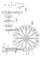
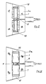
- Fig. 1 eine Flaschenkapsel gemäß der Erfindung in Ansicht,
- Fig. 2 eine Flaschenkapsel in Draufsicht,
- Fig. 3 eine schematische Darstellung des Aufschrumpfvorganges,
- Fig. 4 ein Querschnitt durch die Vorrichtung mit Rotationstisch und Konditionierstrecke,
- Fig. 5 eine schematisch dargestellte Dekoriereinrichtung für die Flachenkapseln,
- Fig. 6 eine Schneid- und Stapeleinrichtung, schematisch dargestellt,
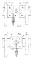
- Fig. 7 eine Draufsicht auf eine geöffnete Form mit Blaspinole in zurückgezogener Lage,
- Fig. 8 eine Draufsicht auf eine geschlossene Form mit Blaspinole in Arbeitsstellung,
- Fig. 9 eine Formhälfte in Seitenansicht mit eingestochener Blaspinole zu Blasbeginn und
- Fig.10 eine Formhälfte in Seitenansicht mit Pinole gegen Blasende (Stützluft).
- 1 is a bottle cap according to the invention in view,
- 2 a bottle cap in top view,
- 3 is a schematic representation of the shrinking process,
- 4 shows a cross section through the device with a rotary table and conditioning section,
- 5 shows a schematically illustrated decorating device for the flat capsules,
- 6 a cutting and stacking device, shown schematically,
- 7 is a plan view of an open mold with a blow pin in a retracted position,
- 8 is a plan view of a closed mold with a blow pin in the working position,
- Fig. 9 is a mold half in side view pierced spinpin at the beginning of the blow and
- Fig.10 a mold half in side view with quill against blowing end (supporting air).
Die in der Fig. 1 dargestellte Flaschenkapsel 1 erweitert sich vom Kapselboden 16 ausgehend zum Kapselrand 17 leicht konisch. In der Nähe des Kapselbodens 16 ist eine Aufreißlasche 15 angeordnet. Der Kapselboden 16 kann eine Prägung 18 aufweisen, um die Flaschenkapsel 1 dekorativ zu gestalten; sie kann aber auch durch Symbole auf den Inhalt der Flasche 19 hinweisen. Nach dem Aufbringen der Flaschenkapsel 1 auf den Flaschenhals 20 wird der Schrumpfprozeß mittels einer Wärmequelle 21 in Gang gesetzt, wobei die Flasche 19 eine Drehbewegung vollführt, wenn diese an der Wärmequelle 21 vorbeigeführt wird. Da der Kapselboden 16 und der Kapselrand 17 erfindungsgemäß am meisten verstreckt sind - bedingt durch die Einschnürung 7 in der Doppelblasform 3a - schrumpfen diese Bereiche entsprechend ein, so daß sie satt am Flaschenhals 20 anliegen. Dadurch wird nicht nur die Zierwirkung der Flaschenkapsel 1 erhöht, sondern es werden auch die unschönen Ausbuchtungen am unteren Kapselrand 17 zuverlässig vermieden. Die Wärmequelle 21 kann als Heizstrecke ausgelegt sein, an welche die zu verkapselnden Flaschen 19 in Drehbewegung vorbeigeführt werden, sie kann aber auch als Heiztunnel ausgebildet sein. (Fig. 2 und Fig. 3).The
Aus einem Extruder 22 (Fig. 4) wird ein Kunststoffschlauch 2 mit vorbestimmter Wandstärke und Durchmesser extrudiert, welcher eine Konditionierstrecke 9 durchläuft. Die Konditionierstrecke 9 hat die Aufgabe, den Kunststoffschlauch 2 im thermoelastischen Bereich zu homogenisieren, bevor derselbe in die geöffnete Doppelblasform 3a eintritt und abgeklemmt wird durch die sich schließenden Formteile. Die Doppelblasformen 3a sind auf einem Rotationstisch 4 montiert, der sich vorzugsweise um eine horizontale Achse 5 dreht. Der Rotationstische 4 ist derart zum extrudierten Kunststoffschlauch 2 angeordnet, daß dieser tangential in die geöffnete Doppelblasform 3a einlaufen kann. Dies hat den Vorteil, daß sich der Rotationstisch 4 kontinuierlich drehen kann. Dadurch verbilligt und vereinfacht sich nicht nur die Konstruktion der gesamten Vorrichtung, sondern es wird ferner der sehr weiche Kunststoffschlauch 2 nur in geringfügigem Maße aus der lotrechten Lage abgelenkt, so daß keine ungewollte Verformung desselben eintritt. Der Rotationstisch 4 kann beispielsweise mit zwölf Umdrehung pro Minute betrieben werden. Hierbei ergibt sich in der dargestellten Ausführungsform eine Kühlzeit von etwa 2,5 sec..A
Die Doppelblasformen 3a sind so konzipiert und am Rotationstisch 4 montiert, daß sie eng aneinander liegen, so daß nur eine geringfügige Menge an Material für Putzen 12 verloren geht. Der extrudierte Kunststoffschlauch 2 wird nicht von Doppelblasform 3a zu Doppelblasform 3a durchtrennt. Er wird lediglich abgeklemmt, so daß es kein Kunststoffschlauchende gibt, welches unkontrolliert in die sich schließende Doppelblasform 3a gelangen kann. Sobald sich die Doppelblasform 3a geschlossen hat, sticht die Blaspinole 8 in die Einschnürung 7 der Doppelblasform 3a ein. Die einströmende Druckluft verformt das in der Doppelblasform eingeschlossene Schlauchstück in bekannter Weise. Da der Kunststoffschlauch beidseitig abgeklemmt ist und sich in Längsrichtung nicht ausdehnen kann, erfolgt eine Ausdehnung ausschließlich in radialer Richtung. Herbei liegt das größte Dehnungsmaß am Kapselrand 17, der im Bereich der Einschmürung 7 angeordnet ist. In den folgenden Stationen bzw. Drehbereichen wird die Stützluft aufrechterhalten bis zur Entleerungsstation 10. Vor dem Erreichen derselben wird die Blaspinole 8 zurückgezogen. (Fig. 7 bis 10). Es können auch zwei oder mehrere Kunststoffschläuche nebeneinander extrudiert werden, wenn ebenso viele Doppelblasformen 3a auf der Drehachse 5 tischförmig angeordnet sind.The double blow molds 3a are designed and mounted on the rotary table 4 in such a way that they lie close together, so that only a small amount of material for cleaning 12 is lost. The extruded
Die Fig. 5 zeigt eine schematisch dargestellte Dekoriereinrichtung 13 zum Bedrucken etc. der Flaschenkapseln 1, die noch in Form eines Doppelkonuses 6 zusammenhängen.5 shows a schematically illustrated decorating device 13 for printing etc. on the
Die Fig. 6 zeigt eine schematisch dargestellte Schneid- und Stapeleinrichtung 11. Hier werden die Einschnürung 7 und die Endputzen 12 abgerennt und die anfallenden Flaschenkapseln 1 nach links und rechts in Stangenform durch eine Stapeleinrichtung 14 gestapelt. Die Stapeleinrichtung kann mit einem Zählwerk verbunden sein, so daß die Flaschenkapseln 1 in Stangenform z.B. von 100 Stück ausgestoßen werden ebenso, wie die Putzen 12 und die Einschnürungsstücke 7 in dafür vorgesehene Behälter 23 entsorgt werden können. Die in Stangenform anfallenden Flaschenkapseln 1 können sofort verpackt werden, weil keine weiteren Nacharbeiten erforderlich sind.6 shows a schematically illustrated cutting and stacking
Claims (14)
Applications Claiming Priority (2)
| Application Number | Priority Date | Filing Date | Title |
|---|---|---|---|
| DE3921587 | 1989-06-30 | ||
| DE3921587A DE3921587A1 (en) | 1989-06-30 | 1989-06-30 | METHOD FOR PRODUCING BOTTLE CAPSULES FROM THERMOPLASTIC PLASTIC AND DEVICE FOR IMPLEMENTING THE METHOD |
Publications (2)
| Publication Number | Publication Date |
|---|---|
| EP0405536A2 true EP0405536A2 (en) | 1991-01-02 |
| EP0405536A3 EP0405536A3 (en) | 1993-01-27 |
Family
ID=6384059
Family Applications (1)
| Application Number | Title | Priority Date | Filing Date |
|---|---|---|---|
| EP19900112331 Withdrawn EP0405536A3 (en) | 1989-06-30 | 1990-06-28 | Method for producing contractable bottle closures from thermoplastic resin and apparatus for executing the method |
Country Status (3)
| Country | Link |
|---|---|
| US (1) | US5118460A (en) |
| EP (1) | EP0405536A3 (en) |
| DE (1) | DE3921587A1 (en) |
Cited By (1)
| Publication number | Priority date | Publication date | Assignee | Title |
|---|---|---|---|---|
| WO1995000314A1 (en) * | 1993-06-18 | 1995-01-05 | Dowbrands Inc. | Quick bottle production changeover utilizing multi-cavity molds in an extrusion blow molding system |
Families Citing this family (3)
| Publication number | Priority date | Publication date | Assignee | Title |
|---|---|---|---|---|
| DE9311004U1 (en) * | 1993-07-23 | 1993-10-14 | Mauser Werke Gmbh | Pallet containers |
| US5840349A (en) * | 1997-02-12 | 1998-11-24 | Graham Engineering Corporation | Rotary blow molding machine |
| US7335007B2 (en) * | 2005-04-18 | 2008-02-26 | Graham Packaging Company, L.P. | Quick change mold |
Citations (5)
| Publication number | Priority date | Publication date | Assignee | Title |
|---|---|---|---|---|
| US3764250A (en) * | 1971-11-01 | 1973-10-09 | Graham Eng Corp | Blow molding machine |
| DE2057901B2 (en) * | 1970-11-25 | 1978-06-22 | Metallkapselfabrik Loos & Co Gmbh, 6200 Wiesbaden | Process for the production of printed bottle caps from plastic shrink film |
| DE2446766B2 (en) * | 1973-10-03 | 1978-08-03 | Hitachi Shipbuilding & Engineering Co., Ltd., Osaka (Japan) | Blow molding device with a turntable |
| DE2123036B2 (en) * | 1970-06-16 | 1979-03-22 | Solvay | Rotating device for the production of hollow plastic bodies |
| US4197071A (en) * | 1978-09-29 | 1980-04-08 | Mueller Engineering & Manufacturing Company Incorporated | Safety device for continuous rotary molding machines |
Family Cites Families (19)
| Publication number | Priority date | Publication date | Assignee | Title |
|---|---|---|---|---|
| DE722225C (en) * | 1939-04-26 | 1942-07-07 | Kalle & Co Ag | Process for the production of shrink rings or shrink capsules, in particular as bottle closures |
| US2790286A (en) * | 1953-05-11 | 1957-04-30 | Goodyear Tire & Rubber | Secondary closures |
| US3110554A (en) * | 1960-06-07 | 1963-11-12 | Mitsubishi Plastics Ind | Method for labeling packages |
| BE606476A (en) * | 1960-07-26 | 1900-01-01 | ||
| US3303243A (en) * | 1963-02-18 | 1967-02-07 | Raychem Corp | Process for producing heat-recoverable articles |
| US3294885A (en) * | 1963-05-09 | 1966-12-27 | Phillips Petroleum Co | Method for blow molding thermoplastic |
| FR1424731A (en) * | 1964-02-14 | 1966-01-14 | Viscose Dev Company Ltd | preformed over-stopper elements applied by shrinkage to containers, and method of manufacture thereof |
| DE1479494C3 (en) * | 1965-10-30 | 1973-12-20 | Johannes 5201 Menden Mehnert | Process for the production of at least one opening in hollow bodies made of plastic |
| US3432586A (en) * | 1966-07-29 | 1969-03-11 | American Can Co | Process for forming plastic containers |
| DE6809330U (en) * | 1968-11-30 | 1969-04-24 | Loos Co Gmbh Metallkapsel | Hfez: plastic capsule |
| US3632249A (en) * | 1969-07-01 | 1972-01-04 | Cypro Inc | Apparatus for molding hollow plastic articles |
| FR2235788B1 (en) * | 1973-07-06 | 1976-05-07 | Solvay | |
| US4018640A (en) * | 1974-10-15 | 1977-04-19 | Owens-Illinois, Inc. | Decorative neckband label for a bottle |
| JPS5148504A (en) * | 1974-10-24 | 1976-04-26 | Komatsu Mfg Co Ltd | CHIKARAFUII DOBATSUKUYO SHIRINDA |
| US4092382A (en) * | 1976-03-31 | 1978-05-30 | Owens-Illinois, Inc. | Method of heat shrinking thermoplastic sleeve wraps on glass containers |
| JPS54107974A (en) * | 1978-02-10 | 1979-08-24 | Sumitomo Electric Ind Ltd | System for making heat-shrinkable tubes |
| US4213750A (en) * | 1978-11-28 | 1980-07-22 | Toyo Seikan Kaisha Limited | Rotary blow molding machine |
| DE3107907C2 (en) * | 1981-03-02 | 1984-06-07 | kabelmetal electro GmbH, 3000 Hannover | Process for the production of shrink tubing, sleeves and caps |
| GB2104825A (en) * | 1981-04-23 | 1983-03-16 | Plastona | Blow moulding |
-
1989
- 1989-06-30 DE DE3921587A patent/DE3921587A1/en active Granted
-
1990
- 1990-06-27 US US07/544,830 patent/US5118460A/en not_active Expired - Fee Related
- 1990-06-28 EP EP19900112331 patent/EP0405536A3/en not_active Withdrawn
Patent Citations (5)
| Publication number | Priority date | Publication date | Assignee | Title |
|---|---|---|---|---|
| DE2123036B2 (en) * | 1970-06-16 | 1979-03-22 | Solvay | Rotating device for the production of hollow plastic bodies |
| DE2057901B2 (en) * | 1970-11-25 | 1978-06-22 | Metallkapselfabrik Loos & Co Gmbh, 6200 Wiesbaden | Process for the production of printed bottle caps from plastic shrink film |
| US3764250A (en) * | 1971-11-01 | 1973-10-09 | Graham Eng Corp | Blow molding machine |
| DE2446766B2 (en) * | 1973-10-03 | 1978-08-03 | Hitachi Shipbuilding & Engineering Co., Ltd., Osaka (Japan) | Blow molding device with a turntable |
| US4197071A (en) * | 1978-09-29 | 1980-04-08 | Mueller Engineering & Manufacturing Company Incorporated | Safety device for continuous rotary molding machines |
Cited By (4)
| Publication number | Priority date | Publication date | Assignee | Title |
|---|---|---|---|---|
| WO1995000314A1 (en) * | 1993-06-18 | 1995-01-05 | Dowbrands Inc. | Quick bottle production changeover utilizing multi-cavity molds in an extrusion blow molding system |
| US5433916A (en) * | 1993-06-18 | 1995-07-18 | Dowbrands, Inc. | Utilizing multi cavity mold in extrusion blow molding process |
| US5551860A (en) * | 1993-06-18 | 1996-09-03 | Dow Brands L.P. | Quick bottle production changeover utilizing multi-cavity molds in an extrusion blow molding system |
| US5556648A (en) * | 1993-06-18 | 1996-09-17 | Dowbrands Inc. | Quick bottle production changeover utilizing multi-cavity molds in an extrusion blow molding system |
Also Published As
| Publication number | Publication date |
|---|---|
| DE3921587A1 (en) | 1991-01-10 |
| US5118460A (en) | 1992-06-02 |
| EP0405536A3 (en) | 1993-01-27 |
| DE3921587C2 (en) | 1991-10-24 |
Similar Documents
| Publication | Publication Date | Title |
|---|---|---|
| DE3543082C2 (en) | ||
| EP2026947B1 (en) | Method for producing hollow bodies from thermoplastic material by extrusion blow moulding with continuous die gap adjustment | |
| DE2161066B2 (en) | METHOD AND DEVICE FOR PRODUCING A HOLLOW BODY FROM THERMOPLASTIC PLASTIC | |
| EP1226015B1 (en) | Method for producing tubular containers | |
| DE2606341A1 (en) | METHOD AND DEVICE FOR MANUFACTURING HOLLOW BODIES FROM PLASTIC BY INJECTION BLADDER | |
| DE2750180A1 (en) | METHOD OF BLOW MOLDING HOLLOW PLASTIC CONTAINERS | |
| EP0317817A2 (en) | Method of making a blow-moulded container from a thermoplastic polyester, especially PET | |
| DE2400951A1 (en) | METHOD AND DEVICE FOR THE MANUFACTURING OF PLASTIC BOTTLES | |
| DE2807199C2 (en) | ||
| EP0062144A2 (en) | Method and apparatus for gauging biaxially oriented thermoplastic bodies | |
| DE2944203A1 (en) | DEVICE FOR SHAPING AND APPLYING PLASTIC SLEEVES TO GLASS BOTTLES | |
| DE2123036C3 (en) | Rotating device for the production of hollow bodies made of plastic | |
| DE2135406A1 (en) | Decorating blow moulded thermoplast bottles - by decorative film shrunk onto parison | |
| DE1461848C2 (en) | Machine for the automatic production, filling and closing of containers made of thermoplastic material | |
| DE2703454C2 (en) | Method of making a bottle by blow molding | |
| DE2715897A1 (en) | METHOD AND DEVICE FOR THE PRODUCTION OF PLASTIC OBJECTS | |
| EP0405536A2 (en) | Method for producing contractable bottle closures from thermoplastic resin and apparatus for executing the method | |
| DE2429221C2 (en) | Method for producing a cup-shaped container or container part | |
| EP2347882A2 (en) | Device and method for manufacturing plastic containers | |
| DE1704022B2 (en) | Method and device for the production and subsequent filling and closing of bottle-shaped hollow bodies made of plastic | |
| DE1778318B2 (en) | Method and device for the production of objects with high impact resistance from hard thermoplastics | |
| DE19618281C1 (en) | Process for the production of injection molded parts and device therefor | |
| AT224559B (en) | Method and device for the production of filled and closed plastic bottles | |
| DE19627675C2 (en) | Thermoformed system for the production of hollow bodies, especially thick-bellied containers with narrow neck areas | |
| DE2036723A1 (en) | Device for producing hollow bodies from thermoplastic material |
Legal Events
| Date | Code | Title | Description |
|---|---|---|---|
| PUAI | Public reference made under article 153(3) epc to a published international application that has entered the european phase |
Free format text: ORIGINAL CODE: 0009012 |
|
| AK | Designated contracting states |
Kind code of ref document: A2 Designated state(s): AT DE ES FR GB GR IT |
|
| PUAL | Search report despatched |
Free format text: ORIGINAL CODE: 0009013 |
|
| AK | Designated contracting states |
Kind code of ref document: A3 Designated state(s): AT DE ES FR GB GR IT |
|
| STAA | Information on the status of an ep patent application or granted ep patent |
Free format text: STATUS: THE APPLICATION HAS BEEN WITHDRAWN |
|
| 18W | Application withdrawn |
Withdrawal date: 19930807 |