EP0405496B1 - Verfahren zur Behandlung von Bildern, die grösser als ein Fenster sind - Google Patents
Verfahren zur Behandlung von Bildern, die grösser als ein Fenster sind Download PDFInfo
- Publication number
- EP0405496B1 EP0405496B1 EP90112244A EP90112244A EP0405496B1 EP 0405496 B1 EP0405496 B1 EP 0405496B1 EP 90112244 A EP90112244 A EP 90112244A EP 90112244 A EP90112244 A EP 90112244A EP 0405496 B1 EP0405496 B1 EP 0405496B1
- Authority
- EP
- European Patent Office
- Prior art keywords
- image
- point
- viewport
- rectangle
- bit map
- Prior art date
- Legal status (The legal status is an assumption and is not a legal conclusion. Google has not performed a legal analysis and makes no representation as to the accuracy of the status listed.)
- Expired - Lifetime
Links
- 238000000034 method Methods 0.000 title claims description 19
- 238000004091 panning Methods 0.000 claims description 5
- 238000012545 processing Methods 0.000 claims description 3
- 210000004027 cell Anatomy 0.000 description 2
- 230000006870 function Effects 0.000 description 2
- 230000004397 blinking Effects 0.000 description 1
- 238000013461 design Methods 0.000 description 1
- 230000000694 effects Effects 0.000 description 1
- 238000010422 painting Methods 0.000 description 1
- 210000000352 storage cell Anatomy 0.000 description 1
- 238000012360 testing method Methods 0.000 description 1
Images


Classifications
-
- G—PHYSICS
- G06—COMPUTING; CALCULATING OR COUNTING
- G06T—IMAGE DATA PROCESSING OR GENERATION, IN GENERAL
- G06T11/00—2D [Two Dimensional] image generation
Definitions
- This invention relates to digital data systems adapted for viewing and manipulating graphic images on a cathode ray tube screen, particularly to systems in which the screen presents a viewport through which all or a portion of the graphic image may be viewed, and most particularly to methods of performing operations on graphic images only portions of which are visible through the viewport.
- CTR cathode ray tube
- Graphic information to be stored in a digital computer system for presentation on a CRT display has generally been stored in two ways, known as "object-based” and "pixel-based”:
- information determinative of the graphic information to be displayed, rather than a direct representation of that information is stored; for example, the coordinates of the beginning and ending points of a line, the coordinates of the corners of a rectangle, the radius and the coordinates of the center of a circle, etc.
- This method has the disadvantage that computation of the screen contents must be performed on the definitional information.
- a pixel In a pixel-based storage scheme, for each elemental portion of the CRT screen (denoted a "pixel", that term being derived from pic ture el ement), memory is organized with a storage cell corresponding to each pixel position on the screen, and information is stored in each cell connoting what is to be displayed at the corresponding pixel position.
- a single bit is stored in a cell denoting whether the corresponding screen pixel position is ON or OFF; in more complex implementations, a multi-bit binary number is stored that might denote such quantities as the color, intensity, and attributes (blinking, reverse video, etc.) of a corresponding screen pixel position.
- This method has the disadvantage that "zooming" (changing the displayed size of the elements) requires extensive manipulation of the stored data.
- the European Patent Application EP-A2-0 172 433 describes ways of panning a viewport across a display occupying a larger virtual screen.
- "zooming out” to view the entire image at once is accomplished by manipulating the bit map in such a way that bits are discarded in order to effectively "shrink” the element sizes; while subsequent “zooming in” can restore the image to the size it had before zooming out, resolution will have been irreparably degraded.
- a complication can occur when a user desires to perform a manipulation (e.g., moving, rotating, changing the fill pattern altering text size or font, etc.) on an element or an area larger than is visible on the screen at one time.
- a manipulation e.g., moving, rotating, changing the fill pattern altering text size or font, etc.
- the prior-art methods for identifying such an element or area consist in using a pointing device (e.g., a "mouse") to identify two diagonally opposite corners of a rectangle containing the element or area to be identified. It is, of course, impossible to do this when the entire perimeter of the desired rectangle cannot be seen at once; under the prior-art methods, the user would be required to zoom out in order to specify the rectangle, encountering the aformentioned loss of granularity.
- the present invention overcomes these drawbacks of the prior art by providing a method wherein the diagonally opposite corners of the rectangle required for demarking an element or area to be manipulated may be identified in separate steps, on portions of the image that need not be simultaneously visible on the screen.
- the user may pan to a portion of the graphic image where he wishes to place one corner of the rectangle, and may identify the position of that corner with his pointing device. He may then pan to a different portion where he desires to place the the diagonally opposite corner, and identify that corner with his pointing device.
- the location of the first corner is "remembered", and the rectangle is drawn; that portion of the rectangle which lies within the currently visible portion of the image is visible to the user. Should the user pan to other portions of the image, portions of the rectangle that lie therein will then be visible.
- the user may thus verify that the rectangle demarks the area he intended, and may then proceed to operate on elements within the rectangle.
- Figure 1 depicts a typical distributed computer system on which the invention might be practiced, comprising a plurality of workstations connected by means of a bus to a mainframe host computer.
- Figure 2 depicts a hypothetical graphics image accessible from a host computer which a user at a terminal or workstation might wish to manipulate.
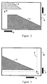
- Figure 3 depicts a portion of the graphics image, such portion being feasible for viewing at the user's terminal or workstation, and illustrates a step in demarking an area or element to be manipulated.
- Figure 4 depicts a different portion of the graphics image, and illustrates a different step in demarking an area or element to be manipulated.
- Figure 5 is a flow chart of the prior-art method of demarking elements within a graphic image.
- Figure 6 is a flow chart of the method of the present invention of demarking elements within a graphic image.
- the invention would typically be practiced in a distributed data processing system such as that shown in Figure 1, comprising a mainframe host computer to which are connected, by means of a bus or communications medium 11, a plurality of terminals or workstations 12.
- Users at the workstations might locally run free-standing applications on data files stored locally at the workstation, might put the workstation into terminal emulation mode and remotely run applications on the host computer, or might download programs or data from the host computer to be run or operated upon at the workstation in free-standing mode.
- the present invention is useful when pixel-based graphic data is downloaded to a workstation for manipulation there.
- the display screen typically provided at a workstation does not have sufficient size or resolution to display a large or complex graphic image in its entirety with good legibility.
- a user might download a graphic image from the host for inclusion in one of his own works which might be of such size or complexity.
- Figure 2 depicts a hypothetical graphic image 1, containing elements 2, 3, and 4.
- Graphic image 1 is a simple one, for illustrative purposes; typical graphic images would contain many more elements, in much closer and more complex juxtaposition.
- the conventional means for identifying element 2 as the element to be manipulated is to draw rectangle ("box") 5 around it, by indicating with a pointing device (e.g., "mouse”) the positions of two diagonally opposite corners of it.
- Figure 3 depicts a tvpical screen display on which appears a portion la of graphic image 1.
- the prior art typically employs "scroll bars" 6 and 7, which indicate a vertical and horizontal strip, respectively, of the overall graphic image, the currently visible portion occupying the area the two strips have in common. Panning to a different area may be accomplished by "dragging" the scroll bars with a mouse, well known in the prior art, or alternatively by typed commands or by the use of the arrow keys with which most terminals are provided.
- Figure 3 is seen to contain the portion of graphic image 1 in which is one of the corners of the desired rectangle 5 (shown in Figure 2), and there is a sufficient amount of detail visible to enable a user to place the corner where he wishes it.
- Figures 5 and 6 are simplified flow charts of the prior-art method of defining the rectangle 5 and the method of the present invention, respectively.
- a mouse click selecting a point for one corner of a rectangle will provide (by means well known to those skilled in the art) the screen coordinates of the point, denoted x1, y1. These will be stored relative to the current bit map-- that is, the bit map for the currently-displayed portion. In order for that action to have any efficacy, the next action from the user must be to provide a second mouse click, denoting the point for the diagonally opposite corner of the rectangle. That point's coordinates, denoted x2, y2 are provided by the mouse. They too are stored relative to the current bit map, and the rectangle thus defined may then be constructed.
- Figure 6 (describing the present invention) is seen to contrast with the prior art in that it describes a routine that must be entered separately for each of the two mouse clicks, and which stores the first coordinate pair relative to the bit map of the entire image; it thus permits the user to pan to a different portion of graphic image 1 in between the two clicks, and permits him to demark the two corners in portions of the graphic image 1 that need not be simultaneously visible to him.
- the user After exiting the routine, the user might invoke other actions, such as panning his screen display to a different portion of the graphic image 1.
- the aforementioned check would pass, leaving the decision box on the "YES" line.
- the second coordinate pair (x2, y2) are stored, and the rectangle is constructed.
- the rectangle would be described, in either the prior-art case or in the case of the present invention, by the coordinate pairs x1,y1;x2,y1;x2,y2;x1,y2;x1,y1.)
- the portion of the rectangle contained within the currently displayed portion of graphic image 1 immediately appears on the screen; should the user pan to some other portion of graphic image 1, any portion of rectangle 5 contained in that portion would then be visible.
Claims (4)
- Verfahren zum Steuern der Kathodenstrahlröhren-Anzeige bei einem Datenverarbeitungssystem eines graphischen Bildes eines Objektes, wobei eine Bildpunkt-Rasterdarstellung, die ein derartiges Bild repräsentiert, in einem Speicher gespeichert wird und wobei ein Prozessor eine Veränderung des Bildes durch geeignetes Modifizieren der Bildpunkt-Rasterdarstellung durchführt und wobei der Darstellungsbereich des Kathodenstrahlröhren-angezeigten Bildes nur ein Teil des ganzen durch die Bildpunkt-Rasterdarstellung repräsentierten Bildes ist;
gekennzeichnet durch die folgenden Schritte:A) Anzeigen eines ersten Randbereiches des zu verändernden Bildteiles in einem ersten Darstellungsbereich;B) Bestimmen, ob ein erster Punkt des ersten Randbereiches gespeichert ist;C) wenn derartiger erster Punkt nicht gespeichert ist, Festlegen, in dem Darstellungsbereich, eines ersten Punktes (x1, y1) in dem ersten Randbereich des Bildteiles und Speichern einer Darstellung des ersten Punktes in Form seines Ortes relativ zu der Bildpunkt-Rasterdarstellung des ganzen Bildes;D) Zurückkehren zu Schritt B);E) wenn derartiger Punkt bereits gespeichert ist, Verschieben des Darstellungsbereiches relativ zu dem Bild, um einen zweiten Randbereich des zu verändernden Bildteiles anzuzeigen;F) Festlegen, in dem Darstellungsbereich, der den zweiten Randbereich anzeigt, eines zweiten Punktes (x2, y2) in dem zweiten Randbereich und Speichern einer Darstellung des zweiten Punktes in Form seines Ortes relativ zu der Bildpunkt-Rasterdarstellung des ganzen Bildes; undG) Verändern des durch die gespeicherten Darstellungen des ersten und zweiten Punktes beschriebenen Bildteiles. - Verfahren nach Anspruch 1, bei welchem Information gespeichert wird, welche ein durch die erste und zweite Punktdarstellung definiertes Rechteck repräsentiert; wobei der Umfang des Rechtecks, relativ zu der Bildpunkt-Rasterdarstellung des Bildes, den Bildteil einschließt; und Verändern des durch das Rechteck eingeschlossenen Bildteiles.
- Verfahren nach Anspruch 1, bei welchem eine Zeigervorrichtung des Systems für die Festlegung eines Punktes in dem Darstellungsbereich sorgt, gekennzeichnet durch die folgenden Schritte:- Festlegen eines ersten Punktes in dem Darstellungsbereich mit der Zeigervorrichtung und Speichern erster Koordinaten, welche die Position des ersten Punktes innerhalb der Bildpunkt-Rasterdarstellung repräsentieren;- Verschieben des Darstellungsbereiches relativ zu dem Bild, um einen zweiten Teil des Bildes anzuzeigen;- Festlegen eines zweiten Punktes in dem Darstellungsbereich mit der Zeigervorrichtung und Speichern zweiter Koordinaten, welche die Position des zweiten Punktes innerhalb der Bildpunkt-Rasterdarstellung repräsentieren; und- Konstruieren der Darstellung eines Rechtecks relativ zu der Bildpunkt-Rasterdarstellung durch Verwenden der ersten und zweiten Koordinaten als die diagonal gegenüberliegenden Ecken des Rechtecks.
- Verfahren nach Anspruch 3, gekennzeichnet durch:- nach dem Schritt des Festlegens des ersten Punktes, jedoch vor dem Schritt des Festlegens des zweiten Punktes;- Speichern dritter Koordinaten, welche die Position eines transistorischen Punktes in dem Darstellungsbereich, welcher der dann gegenwärtigen Position der Zeigervorrichtung entspricht; und- dynamisches Konstruieren der Darstellung eines Rechtecks relativ zu der Bildpunkt-Rasterdarstellung durch Verwendung der ersten und dritten Koordinaten als die diagonal gegenüberliegenden Ecken des Rechtecks.
Applications Claiming Priority (2)
| Application Number | Priority Date | Filing Date | Title |
|---|---|---|---|
| US374520 | 1989-06-30 | ||
| US07/374,520 US5014222A (en) | 1989-06-30 | 1989-06-30 | Method of manipulating images larger than a viewport |
Publications (3)
| Publication Number | Publication Date |
|---|---|
| EP0405496A2 EP0405496A2 (de) | 1991-01-02 |
| EP0405496A3 EP0405496A3 (en) | 1992-10-28 |
| EP0405496B1 true EP0405496B1 (de) | 1997-10-08 |
Family
ID=23477198
Family Applications (1)
| Application Number | Title | Priority Date | Filing Date |
|---|---|---|---|
| EP90112244A Expired - Lifetime EP0405496B1 (de) | 1989-06-30 | 1990-06-27 | Verfahren zur Behandlung von Bildern, die grösser als ein Fenster sind |
Country Status (3)
| Country | Link |
|---|---|
| US (1) | US5014222A (de) |
| EP (1) | EP0405496B1 (de) |
| DE (1) | DE69031550T2 (de) |
Families Citing this family (13)
| Publication number | Priority date | Publication date | Assignee | Title |
|---|---|---|---|---|
| US5247678A (en) * | 1989-10-12 | 1993-09-21 | Texas Instruments Incorporated | Load time linker for software used with a multiprocessor system |
| JPH0685145B2 (ja) * | 1990-11-28 | 1994-10-26 | インターナショナル・ビジネス・マシーンズ・コーポレイション | 複数の選択されたオブジェクトの位置表示方法 |
| US6121966A (en) * | 1992-11-02 | 2000-09-19 | Apple Computer, Inc. | Navigable viewing system |
| US5392388A (en) * | 1992-12-04 | 1995-02-21 | International Business Machines Corporation | Method and system for viewing graphic images in a data processing system |
| US5680629A (en) * | 1992-12-07 | 1997-10-21 | Microsoft Corporation | Method and system for previewing computer output |
| US5452413A (en) * | 1992-12-18 | 1995-09-19 | International Business Machines Corporation | Method and system for manipulating wide-angle images |
| US6035309A (en) * | 1993-02-09 | 2000-03-07 | International Business Machines Corporation | System and method for editing and viewing a very wide flat file |
| US5652901A (en) * | 1994-12-23 | 1997-07-29 | Microsoft Corporation | Method and system for previewing computer output |
| US6101289A (en) * | 1997-10-15 | 2000-08-08 | Electric Planet, Inc. | Method and apparatus for unencumbered capture of an object |
| US6473101B1 (en) * | 1999-02-01 | 2002-10-29 | Gordon F. Grigor | Single surface multi-view panning system and method for multiple displays |
| US7216291B2 (en) * | 2003-10-21 | 2007-05-08 | International Business Machines Corporation | System and method to display table data residing in columns outside the viewable area of a window |
| US7991225B2 (en) * | 2006-03-03 | 2011-08-02 | University Of Alaska | Methods and systems for dynamic color equalization |
| US20090075761A1 (en) * | 2007-09-18 | 2009-03-19 | Joseph Balardeta | Golf gps device and system |
Family Cites Families (3)
| Publication number | Priority date | Publication date | Assignee | Title |
|---|---|---|---|---|
| US4197590A (en) * | 1976-01-19 | 1980-04-08 | Nugraphics, Inc. | Method for dynamically viewing image elements stored in a random access memory array |
| EP0172433A3 (de) * | 1984-08-02 | 1989-04-05 | Tektronix, Inc. | Anzeigeverfahren und -einrichtung mit kursorgesteuerter Bildverschiebung |
| JP2662429B2 (ja) * | 1988-11-14 | 1997-10-15 | キヤノン株式会社 | 画像編集装置 |
-
1989
- 1989-06-30 US US07/374,520 patent/US5014222A/en not_active Expired - Fee Related
-
1990
- 1990-06-27 EP EP90112244A patent/EP0405496B1/de not_active Expired - Lifetime
- 1990-06-27 DE DE69031550T patent/DE69031550T2/de not_active Expired - Fee Related
Also Published As
| Publication number | Publication date |
|---|---|
| EP0405496A3 (en) | 1992-10-28 |
| EP0405496A2 (de) | 1991-01-02 |
| US5014222A (en) | 1991-05-07 |
| DE69031550T2 (de) | 1998-05-20 |
| DE69031550D1 (de) | 1997-11-13 |
Similar Documents
| Publication | Publication Date | Title |
|---|---|---|
| US5689717A (en) | Method and apparatus for the placement of annotations on a display without overlap | |
| JP3598303B2 (ja) | オーバーラップする複数のディスプレイオブジェクトをディスプレイ上に選択的にディスプレイしてアクティブ化する方法、および、コンピュータシステム | |
| US5504853A (en) | System and method for selecting symbols and displaying their graphics objects in a detail window | |
| EP0694878B1 (de) | Verfahren und Vorrichtung zur Hervorhebung der Einzelheit einer Baumstruktur | |
| EP0694829B1 (de) | Ein Verfahren und Gerät zur Darstellung von Datenbanksuchergebnissen | |
| JP3392870B2 (ja) | 図形エッジ・システム | |
| US5388202A (en) | Method and apparatus for generating window borders having pictorial frame elements | |
| US5877762A (en) | System and method for capturing images of screens which display multiple windows | |
| KR100324878B1 (ko) | 가상현실환경에서정보를표시하는방법 | |
| CA2124603C (en) | Method and apparatus for operating on the model data structure of an image to produce human perceptible output in the context of the image | |
| US5487145A (en) | Method and apparatus for compositing display items which minimizes locked drawing areas | |
| US7710429B2 (en) | Stationary semantic zooming | |
| US7061498B2 (en) | Screen display processing apparatus, screen display processing method and computer program | |
| EP0405496B1 (de) | Verfahren zur Behandlung von Bildern, die grösser als ein Fenster sind | |
| EP0447095A2 (de) | Arbeitsraumanzeigen | |
| EP0658859A2 (de) | Verfahren und Vorrichtung zum Übereinandergreifen graphischer Objekte | |
| CA1229439A (en) | Data display system | |
| CN112200899A (zh) | 一种采用实例化渲染实现模型业务交互的方法 | |
| Angus | Interactive graphics systems for CAE | |
| Myers | Display hardware | |
| Hassebrook et al. | ECE REPORT CSP-02-003 | |
| JPH036551B2 (de) | ||
| JPH024953B2 (de) |
Legal Events
| Date | Code | Title | Description |
|---|---|---|---|
| PUAI | Public reference made under article 153(3) epc to a published international application that has entered the european phase |
Free format text: ORIGINAL CODE: 0009012 |
|
| AK | Designated contracting states |
Kind code of ref document: A2 Designated state(s): DE FR GB IT |
|
| PUAL | Search report despatched |
Free format text: ORIGINAL CODE: 0009013 |
|
| AK | Designated contracting states |
Kind code of ref document: A3 Designated state(s): DE FR GB IT |
|
| 17P | Request for examination filed |
Effective date: 19930309 |
|
| RAP1 | Party data changed (applicant data changed or rights of an application transferred) |
Owner name: BULL HN INFORMATION SYSTEMS INC. |
|
| RAP1 | Party data changed (applicant data changed or rights of an application transferred) |
Owner name: BULL HN INFORMATION SYSTEMS INC. |
|
| 17Q | First examination report despatched |
Effective date: 19951222 |
|
| GRAG | Despatch of communication of intention to grant |
Free format text: ORIGINAL CODE: EPIDOS AGRA |
|
| GRAH | Despatch of communication of intention to grant a patent |
Free format text: ORIGINAL CODE: EPIDOS IGRA |
|
| GRAH | Despatch of communication of intention to grant a patent |
Free format text: ORIGINAL CODE: EPIDOS IGRA |
|
| GRAA | (expected) grant |
Free format text: ORIGINAL CODE: 0009210 |
|
| AK | Designated contracting states |
Kind code of ref document: B1 Designated state(s): DE FR GB IT |
|
| REF | Corresponds to: |
Ref document number: 69031550 Country of ref document: DE Date of ref document: 19971113 |
|
| ITF | It: translation for a ep patent filed |
Owner name: BARZANO' E ZANARDO ROMA S.P.A. |
|
| ET | Fr: translation filed | ||
| PLBE | No opposition filed within time limit |
Free format text: ORIGINAL CODE: 0009261 |
|
| STAA | Information on the status of an ep patent application or granted ep patent |
Free format text: STATUS: NO OPPOSITION FILED WITHIN TIME LIMIT |
|
| 26N | No opposition filed | ||
| PGFP | Annual fee paid to national office [announced via postgrant information from national office to epo] |
Ref country code: GB Payment date: 20000602 Year of fee payment: 11 Ref country code: DE Payment date: 20000602 Year of fee payment: 11 |
|
| PGFP | Annual fee paid to national office [announced via postgrant information from national office to epo] |
Ref country code: FR Payment date: 20010531 Year of fee payment: 12 |
|
| PG25 | Lapsed in a contracting state [announced via postgrant information from national office to epo] |
Ref country code: GB Free format text: LAPSE BECAUSE OF NON-PAYMENT OF DUE FEES Effective date: 20010627 |
|
| GBPC | Gb: european patent ceased through non-payment of renewal fee |
Effective date: 20010627 |
|
| PG25 | Lapsed in a contracting state [announced via postgrant information from national office to epo] |
Ref country code: DE Free format text: LAPSE BECAUSE OF NON-PAYMENT OF DUE FEES Effective date: 20020403 |
|
| PG25 | Lapsed in a contracting state [announced via postgrant information from national office to epo] |
Ref country code: FR Free format text: LAPSE BECAUSE OF NON-PAYMENT OF DUE FEES Effective date: 20030228 |
|
| REG | Reference to a national code |
Ref country code: FR Ref legal event code: ST |
|
| PG25 | Lapsed in a contracting state [announced via postgrant information from national office to epo] |
Ref country code: IT Free format text: LAPSE BECAUSE OF NON-PAYMENT OF DUE FEES Effective date: 20050627 |