EP0404681B1 - Elektrostatischer Detektor von Aerosolen - Google Patents
Elektrostatischer Detektor von Aerosolen Download PDFInfo
- Publication number
- EP0404681B1 EP0404681B1 EP90401760A EP90401760A EP0404681B1 EP 0404681 B1 EP0404681 B1 EP 0404681B1 EP 90401760 A EP90401760 A EP 90401760A EP 90401760 A EP90401760 A EP 90401760A EP 0404681 B1 EP0404681 B1 EP 0404681B1
- Authority
- EP
- European Patent Office
- Prior art keywords
- particles
- disks
- aerosol
- flow
- electrostatic
- Prior art date
- Legal status (The legal status is an assumption and is not a legal conclusion. Google has not performed a legal analysis and makes no representation as to the accuracy of the status listed.)
- Expired - Lifetime
Links
Images


Classifications
-
- G—PHYSICS
- G01—MEASURING; TESTING
- G01N—INVESTIGATING OR ANALYSING MATERIALS BY DETERMINING THEIR CHEMICAL OR PHYSICAL PROPERTIES
- G01N15/00—Investigating characteristics of particles; Investigating permeability, pore-volume, or surface-area of porous materials
- G01N15/02—Investigating particle size or size distribution
- G01N15/0266—Investigating particle size or size distribution with electrical classification
-
- G—PHYSICS
- G01—MEASURING; TESTING
- G01T—MEASUREMENT OF NUCLEAR OR X-RADIATION
- G01T7/00—Details of radiation-measuring instruments
- G01T7/02—Collecting means for receiving or storing samples to be investigated and possibly directly transporting the samples to the measuring arrangement; particularly for investigating radioactive fluids
- G01T7/06—Collecting means for receiving or storing samples to be investigated and possibly directly transporting the samples to the measuring arrangement; particularly for investigating radioactive fluids by electrostatic precipitation
-
- G—PHYSICS
- G01—MEASURING; TESTING
- G01N—INVESTIGATING OR ANALYSING MATERIALS BY DETERMINING THEIR CHEMICAL OR PHYSICAL PROPERTIES
- G01N1/00—Sampling; Preparing specimens for investigation
- G01N1/02—Devices for withdrawing samples
- G01N1/22—Devices for withdrawing samples in the gaseous state
- G01N1/2202—Devices for withdrawing samples in the gaseous state involving separation of sample components during sampling
- G01N2001/222—Other features
- G01N2001/2223—Other features aerosol sampling devices
Definitions
- the present invention applies generally to the field of electrostatic capture of aerosol particles with a view to studying them, in particular from the angle of their mobility or their electrical charge as well as to collect them with a view to their submit to analysis systems.
- aerosol designates suspensions of particles of solid or liquid materials in a gas phase, the sizes of said particles being able to range over a very wide spectrum; the finest correspond to molecular aggregates having a few tens of Angstroms, while the largest, which generally come from mechanical actions, can reach dimensions of around one hundred micrometers.
- Microorganisms, viruses, bacteria, or pollens are also considered as aerosol particles and, when suspended in a gas, behave identical to that of other types of inert particles.
- a non-negligible category of aerosol is constituted by radioactive aerosols which can originate from certain radioactive gases, such as, for example, descendants of radon or particles originating from the dispersion in the atmosphere of pulverulent products obtained from nuclear industry.
- devices of this kind have operated with structures having flow shapes with cylindrical or parallelepiped geometry as in GB-A-1533 113.
- the object of the present invention is an electrostatic sensor of aerosol particles, the manufacture and operation of which by subsequent measurement devices is much simpler than in the existing structures previously mentioned and which also offers the very great advantage of allow the carrier gas to flow in the form of a perfect and stable laminar flow.
- This electrostatic sensor of aerosol particles contained in an atmosphere to be examined is characterized in that it comprises two coaxial conductive disks, spaced and parallel, between which an electric field is established by bringing them to different potentials, the space between the two discs communicating over its entire periphery with the atmosphere to be examined, a central aspiration being provided in this space to circulate therein, from the periphery of the discs, part of this atmosphere in the form of a laminar flow centripetal and stable.
- the essential and new characteristic of the electrostatic sensor according to the invention is therefore to work with two disc-shaped electrodes and a flow of the atmosphere to be examined between the two discs in the form of a centripetal and stable laminar flow from the periphery to '' in the center of the device where the flow is sucked.
- An apparatus which is easy to manufacture is thus produced in one fell swoop because conductive discs are very simple to achieve ;
- the particle fixing electrodes are very suitable for analysis, for example by a spectrometer, since the particles are distributed in concentric zones whose electrical mobility decreases from the periphery to the center.
- the structure having a circular symmetry allows a perfectly stable and controlled laminar flow.
- the electrostatic sensor is characterized in that the flow rate of the flow of the atmosphere to be examined is the differential result of the central suction flow rate and a flow rate d peripheral injection of filtered gas, the latter being set to a value lower than that of the suction flow.
- This mode of implementation is particularly well suited to a precise determination of the value of the flow rate of the atmosphere to be examined since this results by definition from the perfectly controlled difference between the flow rate of gas aspirated and the flow rate of filtered gas injected .
- the electrostatic sensor it is advantageous to constitute the electrostatic sensor using a circular cylindrical housing of flattened shape having two axial conduits, one for injecting gas at the bottom of the housing and the other air extraction, at the upper part of this housing, this housing comprising at its upper periphery an annular slot for the entry of the atmosphere to be analyzed and, at its center, a massive thick disc whose upper face supports one of the two conductive discs, the second conductive disc being constituted by the upper cover of the housing, the flow of injection gas bypassing the thick disc after passing through a purification filter and uniform distribution of its flow.
- one of the collecting discs itself is made of a material emitting ionizing radiation.
- a sometimes interesting embodiment of the electrostatic sensor, object of the invention consists in placing in the box which constitutes it, a certain number of sectoral peripheral electrodes each provided with an electrical supply. They can thus be brought to a sufficient potential to trap all the particles entering the corresponding sector and consequently allow the sensor to operate in sequential sectors.
- Another application of the electrostatic sensor which is the subject of the invention lies in the production of an electric mobility selector for aerosol particles, characterized in that at least one of the two coaxial conductive discs is provided with an annular slot. centered on the axis common to the two discs, in connection with suction means, through this slot, particles which would normally have been deposited on the disc at the location of this slot if it did not exist.
- the above suction means consist of a cylindrical casing, attached to one of the discs and containing the slot, and provided with suction tubing to allow the selective extraction of particles with electric mobility corresponding to the radius of the slit.
- Another application of the electrostatic sensor according to the invention lies in the production of an apparatus for obtaining a deposit standard. homogeneous surface area of particles on a disc-shaped substrate.
- Another application of the electrostatic sensor which is the subject of the invention lies in the production of an electrostatic sensor with total collection, capable of selecting all the aerosols having a particle size smaller than a given threshold, characterized in that it comprises, on the path of introduction of the gaseous phase containing the aerosols, an annular slit calibrated to achieve, for an appropriate extraction rate, the inertial separation of the particles with a particle size below the threshold and the deposition of these particles on a collection disc.
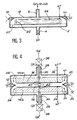
- FIG 1 there is shown the most general and simplest embodiment of the electrostatic aerosol sensor, object of the invention.
- this sensor comprises, in a circular cylindrical case of flattened shape 2, equipped along its central axis with an inlet 4 for the injection rate Q o of atmospheric air for driving under the effect of a pump 6; along its same axis but at the top, an outlet pipe 8 from the atmosphere sucked in under the effect of the suction pump 10.
- At the top of the housing 2 is an annular slot 12 intended for the penetration of the atmosphere to be examined in terms of its aerosol particle content.
- the air flow Q1 to be examined to do this circulate in the housing 2 results from the difference between the air suction flow Q2 under the effect of the pump 10 and the injection flow Q o at the inlet under the effect of the pump 6.
- a solid thick disc 14 electrically conductive or not, on the upper surface of which rests one of the two coaxial conductive discs 16 constituting, with the upper part 18 of the housing 2, the two coaxial conductive discs characteristic of the invention.
- the upper disc 18 is brought to ground while the lower disc 16 is brought to a positive or negative high voltage with respect to this same ground.
- the atmospheric air taken by the pump 6 and injected into the pipe 4 enters the box 2 from the bottom and is distributed therein according to a symmetry of revolution symbolized by the arrows F to pass through an annular filter 20 which completely purifies it by eliminating all the particles in suspension which it can contain and regulates the flow.
- This air once filtered, bypasses the upper part of the thick disc 14 and causes the flow rate Q1 of atmosphere to be examined according to a stable and centripetal laminar flow in the space located between the two coaxial conductive discs 16 and 18. This air is then sucked at the center of the device by the pipe 8 under the effect of the pump 10. After a certain operating time necessary for the electrostatic capture on the discs 16 and 18 of the aerosol particles contained in the flow of atmosphere sampled through opening 12, you can open the device and observe the disc 16 which has an aspect shown in FIG.
- the disc 16 or collection support can generally be any metallic disc to which the high voltage is applied, but it can also be in a particularly interesting case of application, a silicon wafer such that uses them in clean rooms in the microelectronics industry.
- Detailed examination of the distribution and the particle size distribution of the different particles on the disc 16 as seen in FIG. 2, allows using a surface deposition analyzer and computer processing within the reach of those skilled in the art, to determine at will the state of charge of the various particles in suspension in the atmosphere examined .
- This characteristic is particularly advantageous for clean rooms in the microelectronics industry where it is perfectly known that this state of charge of the particles directly conditions their greater or lesser ability to be fixed on the silicon wafers used as substrate in microelectronics.
- a silicon wafer as a collection support 16 offers multiple advantages, such as, for example, the possibility of using at start-up a collection support 16 whose level of surface contamination is guaranteed to be extremely low. by the supplier, for example, with less than five particles with a particle size greater than 0.5 micrometer over the entire surface.
- FIG. 3 of the electrostatic sensor which is the subject of the invention, there is shown an application specially oriented towards biological concerns consisting in identifying the spectrum of bacteria contained in a sample of atmosphere to be analyzed.
- the device of FIG. 3 on which the same elements are recognized as in FIG. 1 bearing the same reference numbers simply comprises, instead of the thick thick disc 14, a Petri dish 22 filled with a electrically conductive gelatinous culture medium 24.
- the bacteria contained in the atmosphere sampled by the annular opening 12 to be analyzed are deposited on the surface of the gelatin 24 where they attach and where we can therefore put them later in evidence and examine them, for example with the naked eye or with an image analyzer, after development of the culture thus sown in a suitable place in temperature.
- the electrical mobility of the bacteria contained in the sampled air is thus easily obtained.
- the filter 20 situated on the path of the drive air injected into the pump 6 plays the double role, on the one hand of retaining the aerosol particles contained in the drive air so that it enters in a perfectly pure state in the space between the two discs 16 and 18 and, on the other hand, to homogenize the gaseous threads thus participating under the conditions for developing a perfectly stable laminar centripetal flow.
- the particles collected in the device of FIG. 1 or the bacteria fixed in that of FIG. 3 correspond to those which carry electrical charges of sign opposite to that of the polarization of the electrode 16 of FIG. 1 or of the Petri dish 22 of FIG. 3. It is therefore possible, by changing the sign of this high-voltage polarization, to thus collect particles and / or bacteria containing positive or negative electrical charges at will.
- the experimenter has two parameters, the flow rates Q o and Q2 on the one hand and the value of the high voltage applied to the conductor 16 or to the Petri dish 22 to choose the domain of the spectrum of particles or bacteria that it wishes to fix for further study.
- FIG. 4 represents a particular embodiment of the electrostatic sensor intended for the collection of aerosol particles as well positively charged than negatively charged.
- This embodiment essentially comprises a circular cylindrical housing 26 having in its diametrical plane of symmetry the annular peripheral opening 12 through which the flow Q1 of atmosphere to be analyzed is sucked.
- the cylindrical housing 26 comprises at the upper part, as at the lower part, two concentric conduits, namely an external conduit 28 intended for the injection of the flow rate Q o and at the internal part a second concentric conduit 30 intended for the suction of the flow Q2 under the effect of the pumps not shown.
- the two conductive discs 16 and 18 intended for the collection of charged particles are located face to face and placed symmetrically on either side of the diametrical plane of symmetry of the box 26. They are worn as in the example of Figure 1, by massive thick discs 14a and 14b.
- the housing 26 is grounded and each of the conductive discs 16 and 18 is carried by a conductor such as 32 for the disc 16 and 34 for the disc 18 respectively at a high positive and negative high voltage symmetrical with respect to the ground so collecting on the conductive disc 16 negatively charged aerosol particles and, on the conductive disc 18, the positively charged aerosol particles.
- two passive mechanical filters 36 and 38 are placed on the suction outlets of the two conduits 30.
- FIG. 5 shows an improved embodiment of the electrostatic sensor according to FIG. 1 in which the peripheral part of the housing 2 is provided with planar electrodes such as 40, 42 and 44, connected to high voltage sources 46, 48 and 50 thus allowing any number of these electrodes to be energized at will.
- planar electrodes such as 40, 42 and 44
- high voltage sources 46, 48 and 50 thus allowing any number of these electrodes to be energized at will.
- these have a sectoral shape on the periphery and the flow is radial and centripetal, it suffices to block the operation of a sector corresponding to a given electrode, to put it under a sufficient voltage to stop, as soon input 12, all of the charged particles of sign opposite to that of the polarity chosen for said electrode.
- each of the sectoral electrodes 40, 42 and 44 etc ... functions as an electrostatic trap. If they are all supplied, they stop all the particles, none of which will therefore be collected on the collection disk 16. If, on the contrary, any of the electrodes 40, 42, 44, etc. is not supplied, it is that is to say, is left at ground potential, the corresponding angular sector will allow the charged particles to pass to the corresponding sector of the plate 16. It is therefore possible to deposit on this same support disc 16, sector after sector, according to a preset sequence. This can be very useful for monitoring the evolution of contamination in a particular environment over time, gradually triggering the operation of the sensor according to juxtaposed radial sectors.
- Figure 6 is an improvement of the electrostatic sensor of Figure 1 arranged to allow the collection of all aerosol particles contained in an atmospheric sample to be examined.
- the charge of all the aerosol particles contained in the sample to be examined is loaded using charges which are all of the same sign.
- this is obtained using an annular chamber 52 situated at the inlet 12 of the flow of atmosphere to be examined and containing an ionizing source 54 accompanied by an equipotential grid 56.
- the ionizing source 54 can be for example an alpha radioactive source and causing inside the entire annular chamber 52, a creation of pairs of positive and negative ions.
- the polarization of all the particles using charges of the same sign before their examination by the sensor is carried out using charged microtips causing the ionization by crown effect, said microtips being distributed in an annular chamber identical to the chamber 52 of FIG. 6.
- This grid 60 has a double role in that it extracts on the one hand the ions of a single polarity in the region where the aerosols introduced by the annular lateral slit 12 circulate before their aspiration by the tube axial and that it establishes a uniform electric field in this region so that the aerosols thus charged are precipitated on the collection disc 18.
- This collection disc 18 must obviously have at least one conductive face and can be made of any metallic material , or more simply it can be a slice of standard silicon if one wishes to make an examination in the atmosphere a priori very little polluted of a clean room of the micro industry electronic.
- suction scheme implemented in the embodiment of FIG. 7, characterized by a single central aspiration, and not by a central aspiration associated with a peripheral injection, is not linked to the existence of a surface source of ionization, but can be transposed to all of the modes of embodiment of the invention previously described.
- mobility selector or differential mobility analyzer an apparatus capable of sorting the aerosol particles contained in a gaseous phase determined as a function of their electric mobility, a size well known and the definition of which has been recalled previously.
- Such devices already exist in the industry and are used either to produce aerosols of known electrical mobility, or even in certain cases, aerosols having a perfectly determined diameter and often designated by specialists under the terminology of monodispersed aerosols (in Anglo-Saxon terminology "mono-dispersed”).
- the electric mobility selectors have a cylindrical symmetry and the two electrodes present consist respectively of two hollow metallic coaxial conductive cylinders of different diameters.
- the central cylinder is provided with a circular slot into which particles of determined electrical mobility are sucked.
- the lateral edges of the preceding electrostatic sensor have two openings: an upper opening 70 through which the aerosols to be analyzed are sucked in and a lower opening 72 provided with a cleanliness filter 74 through which is injected the sweeping air extracted through the tubing 8.
- the lower conductive disc 16 is provided with an annular slot 76 centered on the common axis 78 of the two discs 16 and 18 and, by this annular slot 76, the particles whose average trajectory between the point A and point B is shown diagrammatically in dotted line 80 on the figure; these particles are sucked through the slot 76 due to the fact that their normal place of impact in the absence of this slot 76 would have been the point B located at the distance from the axis 78 equal to the radius of the annular slot 76.
- several means can be used without departing from the scope of the invention; in particular, and as is the case in the embodiment shown in FIG.
- the example which follows relates to an application of the electrostatic sensor to the production of an apparatus for obtaining a standard for homogeneous surface deposition of particles on a disc-shaped substrate.
- particle concentration standards have been produced by etching microscopic points on a substrate, the number of these points being perfectly determined and known by photolithographic process. It is obvious that this technique is delicate to implement and that it leads to relatively expensive standards.
- the present example relates to a process which makes it possible to carry out standard surface contaminations, both in size and in concentration while guaranteeing a particularly uniform deposit.
- This process can moreover be applied to deposit on substrates particles of physicochemical nature perfectly mastered for! Es research needs, in particular in microelectronics.
- the Applicant has actually found that it was possible to apply the electrostatic sensor of aerosol particles object of the invention to obtain such a deposit by constituting simply one of the two conductive discs of the electrostatic sensor by the substrate on which we want to deposit the standard contamination.
- FIG. 9 which shows an electrostatic sensor
- the senor is represented diagrammatically by its two coaxial conductive discs 16 and 18 and its tube 8 for suction of the extraction flow rate Q.
- the entry of aerosol particles which it is desired to deposit on the disc lower 16 is located on the surface of the disc 18 and takes the form of an annular injection slot 12 through which these particles are sucked. If the suction gas flow through the annular slot 12 is q, it is clear that the driving gas flow required at the open periphery of the two coaxial discs 16 and 18 is equal to Qq.
- FIG. 10 shows the electrostatic sensor 87 provided with its concentric electrode discs 16 and 18 and with its annular slot 12 for access to the aerosols to be dispersed.
- the assembly being located in a closed enclosure 86 supplied by the pipe 88 using a gas flow containing the aerosol particles.
- the main suction flow Q of the electrostatic sensor 87 circulates in the latter and in the enclosure 86 by means of a pipe 90; it is injected through a filter 92 and rejected outside the enclosure 86 after having fulfilled its driving function.
- a pipe 94 makes it possible to extract and evacuate towards the outside through the filter 96, the excess atmosphere possibly contained in the enclosure 86.
- the aerosol particles which penetrate into the enclosure 86 via the line 88 have predetermined characteristics and in particular the same value for all the particles of two out of three of the magnitudes that are the electric mobility, the charge and the dimension.
- the aerosol is produced using calibrated latex beads and the skilled person knows then that it is easy, by passing the aerosol thus formed through '' a differential mobility selector, to obtain a population of aerosol particles which all have the same electrical charge, the same dimension and the same electrical mobility.
- This particularly easy-to-implement case makes it possible in particular to supply the pipe 88 at the entrance to the enclosure 86.
- This example relates to the application of the electrostatic sensor to the production of an apparatus which makes it possible to capture all the aerosols having a particle size smaller than a given threshold.
- Such an apparatus has a large number of possible applications, one of the main ones being the study in an atmosphere comprising aerosols dispersed in particle size of those which are normally inhaled by the human respiratory tract, since it is admitted generally that the particles inspirable by the man and likely to cross the larynx are those which have a particle size lower than 10 micrometers.
- This device therefore makes it possible to collect in any atmosphere all the dust that a human being, present in this atmosphere, would have inhaled.
- the total selection apparatus, object of the present application combines the principle of particle size selection by inertial separation with an electrostatic sensor for total collection as defined with reference to FIG. 7.
- FIG. 11 which schematically shows the production of the total selection sensor
- the sensor proper can be recognized as it was described in FIG. 7 with its electrodes 16 and 18, the electrode 16 of which is an ionizing emitter, its equipotential grid 60 and its central suction pipe 8 through which the flow Q2 is evacuated.
- a selection structure has been combined with this structure. particle size distribution by inertial separation which essentially consists, in the gas stream penetrating at the periphery 12 of the device at a flow rate Q1 + Q2 of an annular slot 98 with a width of the order of a millimeter through which is sucked into the space between the coaxial electrodes 16 and 18 the flow of atmosphere Q2.
- the remaining fraction Q1 of the inlet flow at 12 into the device which does not enter the electrostatic sensor is discharged directly by another central tube 100.
- the slot 98 in combination with the suction flow rate Q2 which passes through it constitutes an inertial separator for particle size selection and it is by suitable choice and according to methods known to those skilled in the art that the cutting is carried out at a desired particle size of the aerosol particles entering the sensor by choosing the size of the annular slot and the flow rate Q2 which passes through it.
- the dimensions of the annular slot 98 and the value of the flow rate Q2 are precisely chosen to obtain a cut-off of particles with an aerodynamic diameter of 10 micrometers, which achieves, by physical means , the size selection which would have taken place in the larynx of a human being. In this way, all the particles which this human being would have inhaled penetrate through the slot 98 and are then absorbed and fixed on the collection plate 18 of the electrostatic sensor with total selection for the purpose of a subsequent analysis.
Claims (15)
- Elektrostatischer Detektor für in einer zu untersuchenden Atmosphäre enthaltene Aerosole,
dadurch gekennzeichnet, daß er zwei voneineander beabstandete und paralelle koaxiale Leiterscheiben (16, 18) umfaßt, zwischen denen ein elektrisches Feld aufgebaut wird, indem sie an verschiedene Potentiale gelegt werden, wobei der Zwischenraum zwischen den beiden Scheiben an seinem gesamten Umfang mit der zu untersuchenden Atmosphäre in Verbindung steht, wobei eine zentrale Absaugvorrichtung (8) in diesem Raum vorgesehen ist, um darin, ausgehend vom Scheibenumfang, einen Teil dieser Atmosphäre als laminare, zentripetale und stationäre Strömung fließen zu lassen. - Elektrostatischer Detektor nach Anspruch 2, dadurch gekennzeichnet, daß der Strömungsdurchfluß Q1 der zu untersuchenden Atmosphäre die Differenz zwischen dem zentralen Absaugfluß Q2 und einem Fluß Qo von gefiltertem Gas ist, das über den Umfang eingeleitet wird, wobei letzterer auf einen Wert eingestellt wird, der unter dem des Absaugflusses liegt.
- Elektrostatischer Detektor nach Anspruch 1, dadurch gekennzeichnet, daß er aus einem flachen, kreisförmigen, zylindrischen Gehäuse (2) gebildet ist, das zwei axiale Leitungen besitzt, die eine zum Gaseinleiten (4) am Unterteil des Gehäuses und die andere zum Gasausleiten (8) am Oberteil des Gehäuses, wobei dieses Gehäuse an seinem oberen Umfang einen ringförmigen Spalt (12) zum Eintritt der zu analysierenden Atmosphäre und in seiner Mitte eine dicke, massive Scheibe (14) umfaßt, deren Oberseite die eine der beiden Leiterscheiben (16) trägt, wobei die zweite Leiterscheibe (18) vom oberen Deckel des Gehäuses gebildet ist, und der Einleit-Gasfluß die dicke Scheibe umgibt, nachdem er einen Filter (20) zur Reinigung und gleichmäßigen Strömungsverteilung duchlaufen hat.
- Elektrostatischer Detektor nach Anspruch 3, dadurch gekennzeichnet, daß er am Eingang des ringförmigen Spalts (12) und im Gehäuse angeordnet eine bestimmte Anzahl von Elektroden (40, 42, 44, ...) umfaßt, jede mit einer elektrischen Versorgung ausgestattet, um sie auf ein Potential zu bringen, das ausreicht, um die in den entsprechenden Sektor eintretenden Teilchen einzufangen und folglich eine Arbeitsweise des Detektors in sequentiellen Sektoren zu ermöglichen.
- Elektrostatischer Detektor nach Anspruch 2, dienend zum Sammeln von Aerosolteilchen beider Ladungsvorzeichen, dadurch gekennzeichnet, daß er aus einem kreisförmigen, zylindrischen Gehäuse (26) gebildet ist, das in seiner diametralen Symmetrieebene eine ringförmige Außenöffnug (12) zum Ansaugen des Flusses zu untersuchenden Gases und entlang seiner Kreissymmetrieachse am Oberteil wie am Unterteil je zwei konzentrische Leitungen (28, 30) besitzt, die jeweils in der Mittelleitung (30) für den Absaugfluß und in der äußeren Leitung (28) für den Einleitfluß dienen, wobei die beiden Leiterscheiben (16, 18) symmetrisch, sich gegenüberliegend auf beiden Seiten der diametralen Symmetrieebene angeordnet und an zur Masse symmetrische Potentiale von entgegengesetzten Vorzeichen gelegt sind, wobei sich jede Mittel-Absaugleitung in den Zwischenraum zwischen den beiden Scheiben durch eine Öffnung (40, 42) öffnet, die in der Mitte jeder Scheibe ausgebildet ist.
- Anwendung des elektrostatischen Detektors nach einem der Ansprüche 1 bis 5 zum Ausführen eines Spektrometers für Aerosolteilchen aufgrund ihrer elektrischen Beweglichkeit, dadurch gekennzeichnet, daß die elektrische Feldstärke zwischen den beiden Scheiben und der laminare, radiale Strömungsfluß der zu untersuchenden Atmosphärenprobe so gewählt werden, daß erreicht wird, daß sich mindestens ein Teil dieser Teilchen in ringförmigen, konzentrischen Zonen auf den Scheiben verteilt anlagert, wobei das Beweglichkeitsspektrum durch Berechnung oder informatische Verarbeitung erschlossen wird, ausgehend vom Überprüfen der Zonenlage und -dichte, sowie der Teilchenkörnung.
- Anwendung des elektrostatischen Detektors nach einem der Ansprüche 1 bis 5 zum Ausführen eines Kollektors von Aerosolteilchen, die in einer zu untersuchenden Atmosphäre enthalten sind, dadurch gekennzeichnet, daß der in den Detektor einströmende Teil der zu untersuchenden Atmosphäre Mitteln ausgesetzt wird zum elektrischen Laden mit gleichem Vorzeichen aller Teilchen, die das Aerosol bilden.
- Anwendung des elektrostatischen Detektors nach Anspruch 7, dadurch gekennzeichnet, daß die Mittel zur elektrischen Ladung am Eingang des Gasflusses zwischen den beiden Scheiben gelegen sind und aus einer ringförmigen Kammer (52) gebildet sind, umfassend eine ionisierende, radioaktive Quelle (54) und ein Polarisationsgitter (56), die die Teilchen mit gleichem Vorzeichen laden, bevor sie in den Detektor eintreten.
- Anwendung des elektrostatischen Detektors nach Anspruch 7, dadurch gekennzeichnet, daß die Mittel zum elektrischen Laden der Teilchen am Eingang des Gasflusses zwischen den beiden Scheiben gelegen sind und aus einer ringförmigen Kammer gebildet sind, die mit Mikrospitzen versehen ist, die an Hochspannung gelegt sind und durch den Koronaeffekt die Ionisation hervorrufen.
- Anwendung des elektrostatischen Detektors nach Anspruch 7, dadurch gekennzeichnet, daß die Mittel zum elektrischen Laden der Teilchen dadurch gebildet sind, daß eine der beiden Scheiben (16) selbst, eine ionisierende Strahlung emittiert.
- Anwendung des elektrostatischen Detektors nach mindestens einem der vorigen Ansprüche, dadurch gekennzeichnet, daß die Leitung zum Gasausleiten mit einem statischen Filter (36) ausgerüstet ist, um in der zu untersuchenden Atmosphäre eventuell enthaltene neutrale Aerosolteilchen zu sammeln.
- Anwendung des elektrostatischen Detektors nach Anspruch 1 zum Ausführen eines Selektors für Aerosolteilchen aufgrund ihrer elektrischen Beweglichkeit, dadurch gekennzeichnet, daß mindestens die eine der beiden koaxialen Leiterscheiben (16, 18) mit einem ringförmigen Spalt (76) versehen ist, der auf der gemeinsamen Achse der beiden Scheiben zentriert ist in Verbindung mit Mitteln (84) zum Absaugen von Teilchen über diesen Spalt, die sich normalerweise auf der Scheibe an der Stelle dieses Spalts abgelegt hätten, wenn der Spalt nicht existierte.
- Anwendung des elektrostatischen Detektors nach Anspruch 12, dadurch gekennzeichnet, daß die Absaugmittel ein zylindrisches Gehäuse (82) umfassen, das unter der Scheibe (16) befestigt ist, den Spalt (76) einschließt und mit einem Absaug-Rohransatz (84) versehen ist, um das selektive Ausleiten von Teilchen zu ermöglichen, die die dem Radius des Spalts (76) entsprechende elektrische Beweglichkeit haben.
- Anwendung des elektrostatischen Detektors nach Anspruch 1 zum Ausführen eines Geräts, das homogene Probe-Oberflächenablagerungen von Teilchen auf einem scheibenförmigen Substrat erzeugt, dadurch gekennzeichnet, daß dem elektrostatischen Detektor, dessen Substrat die eine der Leiterscheiben bildet, mittels eines Aerosolflusses Teilchen zugeführt werden, die denselben Wert zweier von drei Größen, nämlich elektrische Beweglichkeit, Ladung und Ausdehnung, gemeinsam haben, und dadurch, daß während der Ablagerung die Potentialdifferenz V zwischen den Detektorscheiben als Funktion der Zeit nach dem Gesetz:
 - h der Halbabstand zwischen den Platten ist;- Z die den Teilchen gemeinsame elektrische Beweglichkeit ist;- rA der Abstand des Aerosol-Einleitpunktes bezüglich der Detektorachse ist;- Q der Ausleitfluß der Gasphase aus dem Detektor ist;- N die Teilchenkonzentration im Ausleitfluß Q ist, wenn V = 0;- S die Oberflächen-Teilchendichte ist, die auf der Kollektorscheibe erreicht werden soll;- t die Zeit ist.
 - Anwendung des vollständig sammelnden elektrostatischen Detektors nach Anspruch 10 zum Ausführen eines Detektors mit vollständiger Selektion aller Aerosole, die eine Körnung unter einer gegebenen Schwelle haben, dadurch gekennzeichnet, daß dieser Detektor auf dem Einleitweg der Gasphase, die die Aerosole umfaßt, einen ringförmigen, kalibrierten Spalt (98) umfaßt, um für einen geeigneten Ausleitfluß die Ablenkungsfilterung von Teilchen mit einer Körnung unter der gewählten Schwelle zu erreichen.
Applications Claiming Priority (4)
| Application Number | Priority Date | Filing Date | Title |
|---|---|---|---|
| FR8908400A FR2649795B1 (fr) | 1989-06-23 | 1989-06-23 | Capteur electrostatique de particules d'aerosol |
| FR8908400 | 1989-06-23 | ||
| FR9002413 | 1990-02-27 | ||
| FR9002413A FR2658916B2 (fr) | 1990-02-27 | 1990-02-27 | Capteur electrostatique de particules d'aerosol et appareils en comportant application. |
Publications (2)
| Publication Number | Publication Date |
|---|---|
| EP0404681A1 EP0404681A1 (de) | 1990-12-27 |
| EP0404681B1 true EP0404681B1 (de) | 1993-05-26 |
Family
ID=26227420
Family Applications (1)
| Application Number | Title | Priority Date | Filing Date |
|---|---|---|---|
| EP90401760A Expired - Lifetime EP0404681B1 (de) | 1989-06-23 | 1990-06-21 | Elektrostatischer Detektor von Aerosolen |
Country Status (4)
| Country | Link |
|---|---|
| US (1) | US5117190A (de) |
| EP (1) | EP0404681B1 (de) |
| JP (1) | JP2874786B2 (de) |
| DE (1) | DE69001719T2 (de) |
Families Citing this family (25)
| Publication number | Priority date | Publication date | Assignee | Title |
|---|---|---|---|---|
| US5072188A (en) * | 1989-12-07 | 1991-12-10 | Hughes Aircraft Company | Apparatus for measuring the conductivity of paint spray using an electromagnetic wave |
| US5128539A (en) * | 1990-08-15 | 1992-07-07 | The United States Of America As Represented By The United States Department Of Energy | Apparatus having reduced background for measuring radiation activity in aerosol particles |
| FR2720505B1 (fr) * | 1994-05-24 | 1996-07-05 | Commissariat Energie Atomique | Sélecteur de particules chargées, à haute sensibilité. |
| FR2720506B1 (fr) * | 1994-05-24 | 1996-07-05 | Commissariat Energie Atomique | Spectromètre de particules submicroniques. |
| US5596136A (en) * | 1995-07-27 | 1997-01-21 | California Institute Of Technology | Radial differential mobility analyzer |
| US5922976A (en) * | 1995-10-12 | 1999-07-13 | California Institute Of Technology | Method of measuring aerosol particles using automated mobility-classified aerosol detector |
| FR2745084B1 (fr) * | 1996-02-15 | 1998-03-13 | Commissariat Energie Atomique | Selecteur de mobilite dynamique des particules d'un aerosol |
| FR2745086B1 (fr) * | 1996-02-15 | 1998-03-13 | Commissariat Energie Atomique | Selecteur de particules chargees, en fonction de leur mobilite electrique et de leur temps de relaxation |
| US6003389A (en) * | 1996-09-05 | 1999-12-21 | California Institute Of Technology | Enhanced automated classified aerosol detector |
| US6125845A (en) * | 1997-08-29 | 2000-10-03 | Tsi Incorporated | Respirator fit-testing with size selected aerosol |
| DE602005010872D1 (de) * | 2005-09-20 | 2008-12-18 | Varian Spa | Vorrichtung und Verfahren zur Erfassung der Anwesentheit eines Prüfgases |
| US7723677B2 (en) * | 2006-07-18 | 2010-05-25 | Ramen, S.A. | Wide range, very high resolution differential mobility analyzer (DMA) |
| US8372183B2 (en) | 2007-06-12 | 2013-02-12 | Orono Spectral Solution, Inc. | Detection system for airborne particles |
| US8192523B1 (en) | 2008-02-22 | 2012-06-05 | Tsi Incorporated | Device and method for separating and increasing the concentration of charged particles in a sampled aerosol |
| US8309029B1 (en) * | 2009-03-26 | 2012-11-13 | The United States Of America As Represented By The Secretary Of The Army | Virus and particulate separation from solution |
| US9177774B2 (en) * | 2010-01-15 | 2015-11-03 | California Institute Of Technology | Continuous flow mobility classifier interface with mass spectrometer |
| GB201016222D0 (en) * | 2010-09-27 | 2010-11-10 | Natural Enviromental Res Council | Aerosol detection |
| US9140653B2 (en) | 2010-10-08 | 2015-09-22 | Tsi Incorporated | Spark emission particle detector |
| GB201113478D0 (en) * | 2011-08-04 | 2011-09-21 | Cambridge Entpr Ltd | Sensing systems |
| JP6030353B2 (ja) * | 2012-03-23 | 2016-11-24 | シャープ株式会社 | 粒子捕集装置およびそれを備えた粒子検出装置 |
| WO2017083621A1 (en) * | 2015-11-13 | 2017-05-18 | Daren Chen | Curved classifiers and classification methods |
| FR3072309B1 (fr) * | 2017-10-12 | 2023-02-10 | Commissariat Energie Atomique | Methode et dispositif de tri de fibres en suspension dans un aerosol par la combinaison de forces electrostatiques et de gravite |
| FR3072310B1 (fr) * | 2017-10-12 | 2022-04-15 | Commissariat Energie Atomique | Methode et dispositif de tri de fibres en suspension dans un aerosol par la combinaison de forces electrostatiques et centrifuge |
| US10775290B2 (en) * | 2017-10-16 | 2020-09-15 | California Institute Of Technology | Highly portable radial differential mobility analyzer |
| FR3086891B1 (fr) * | 2018-10-03 | 2020-12-18 | Valeo Systemes Thermiques | Composant electronique pour vehicule automobile |
Family Cites Families (8)
| Publication number | Priority date | Publication date | Assignee | Title |
|---|---|---|---|---|
| US3566107A (en) * | 1967-11-24 | 1971-02-23 | Hewlett Packard Co | Nickel 63 electron capture detector |
| GB1533113A (en) * | 1976-01-26 | 1978-11-22 | Laws C | Instruments for measuring the density of atmospheric ions |
| US4117715A (en) * | 1977-07-05 | 1978-10-03 | Ransburg Corporation | Apparatus for measuring charge on, and density of, airborne particulates |
| SU657372A1 (ru) * | 1977-07-13 | 1979-04-15 | Предприятие П/Я В-2346 | Устройство дл измерени зар да частиц порошкового материала |
| DE2843246A1 (de) * | 1978-10-04 | 1980-04-17 | Gerdts Gustav F Kg | Messverfahren und messvorrichtung zum erfassen elektrisch leitender fluessigkeitstropfen |
| US4387369A (en) * | 1978-10-11 | 1983-06-07 | Johnson Controls, Inc. | Broad spectrum charged electric field polar gas sensing and detection system |
| US4556849A (en) * | 1983-03-01 | 1985-12-03 | Vsesojuzny Nauchno-Issledovatelsky Institut Nerudnykh Stroitelnykh Materialov Gidromekhanizatsii | Apparatus for measuring the grain-size composition of powders |
| CH674267A5 (de) * | 1987-09-10 | 1990-05-15 | Bbc Brown Boveri & Cie |
-
1990
- 1990-06-21 DE DE90401760T patent/DE69001719T2/de not_active Expired - Lifetime
- 1990-06-21 EP EP90401760A patent/EP0404681B1/de not_active Expired - Lifetime
- 1990-06-22 US US07/542,030 patent/US5117190A/en not_active Expired - Lifetime
- 1990-06-22 JP JP2165502A patent/JP2874786B2/ja not_active Expired - Lifetime
Also Published As
| Publication number | Publication date |
|---|---|
| US5117190A (en) | 1992-05-26 |
| JP2874786B2 (ja) | 1999-03-24 |
| JPH0337561A (ja) | 1991-02-18 |
| DE69001719D1 (de) | 1993-07-01 |
| EP0404681A1 (de) | 1990-12-27 |
| DE69001719T2 (de) | 1993-11-18 |
Similar Documents
| Publication | Publication Date | Title |
|---|---|---|
| EP0404681B1 (de) | Elektrostatischer Detektor von Aerosolen | |
| EP0685727B1 (de) | Teilchenspektrometer, i.B. für submikronische Teilchen | |
| US8404491B2 (en) | Luminescent chemical sensor integrated with at least one molecular trap | |
| FR2658913A1 (fr) | Procede et dispositif d'etalonnage d'un compteur de particules. | |
| EP3328548A1 (de) | Verfahren und vorrichtung zum sammeln selektiver aerosolpartikel nach partikelgrösse | |
| KR102459195B1 (ko) | 표면 증강 라만 분광의 방법, 사용 및 장치 | |
| US7838825B2 (en) | Method and apparatus for incorporating electrostatic concentrators and/or ion mobility separators with Raman, IR, UV, XRF, LIF and LIBS spectroscopy and/or other spectroscopic techniques | |
| EP2880438B1 (de) | Gasanalysevorrichtung mit einem einen mikro-reflektron aufweisenden massenspektrometer | |
| US9810606B2 (en) | Methods and devices for vapor sampling | |
| WO2017017185A1 (fr) | Methode d'epuration selective d'aerosols | |
| FR2547421A1 (fr) | Procede de detection de la contamination atmospherique par des aerosols de particules alpha et detecteur portatif de cette contamination mettant en oeuvre le procede | |
| FR2745086A1 (fr) | Selecteur de particules chargees, en fonction de leur mobilite electrique et de leur temps de relaxation | |
| JP2003214997A (ja) | 大気中の浮遊粒子状物質の捕集装置および捕集した浮遊粒子状物質の測定方法 | |
| EP3694650B1 (de) | Verfahren und vorrichtung zum sortieren von in einem aerosol suspendierten fasern unter verwendung einer kombination von elektrostatischen kräften und schwerkraft | |
| Vo‐Dinh et al. | Surface‐enhanced Raman detection of chemical vapors with the use of personal dosimeters | |
| FR2649795A1 (fr) | Capteur electrostatique de particules d'aerosol | |
| EP0685725B1 (de) | Hochempfindliche Auswahleinrichtung für geladene Teilchen | |
| Gridin et al. | Particulate material analysis by a laser ionization fast conductivity method. Water content effects | |
| JP3758603B2 (ja) | 大気中の浮遊粒子状物質の捕集装置 | |
| FR3071613B1 (fr) | Appareil de detection et d'identification chimique en temps reel de particules contenues dans des aerosols, notamment dans les aerosols atmospheriques | |
| FR2658916A2 (fr) | Capteur electrostatique de particules d'aerosol et appareils en comportant application. | |
| EP0402193A1 (de) | Verfahren und Vorrichtung zur Messung der Konzentration verschiedener Radon-Isotope in einer gasförmigen Atmosphäre | |
| FR2604257A1 (fr) | Instrument de mesure de particules ultra-fines | |
| EP0790495A1 (de) | Dynamischer Beweglichkeitsselektor für Aerosolteilchen | |
| JP2003329552A (ja) | 大気中の花粉の捕集装置および測定装置並びに測定方法 |
Legal Events
| Date | Code | Title | Description |
|---|---|---|---|
| PUAI | Public reference made under article 153(3) epc to a published international application that has entered the european phase |
Free format text: ORIGINAL CODE: 0009012 |
|
| AK | Designated contracting states |
Kind code of ref document: A1 Designated state(s): DE GB IT NL |
|
| 17P | Request for examination filed |
Effective date: 19910531 |
|
| 17Q | First examination report despatched |
Effective date: 19920324 |
|
| GRAA | (expected) grant |
Free format text: ORIGINAL CODE: 0009210 |
|
| AK | Designated contracting states |
Kind code of ref document: B1 Designated state(s): DE GB IT NL |
|
| REF | Corresponds to: |
Ref document number: 69001719 Country of ref document: DE Date of ref document: 19930701 |
|
| ITF | It: translation for a ep patent filed |
Owner name: JACOBACCI CASETTA & PERANI S.P.A. |
|
| GBT | Gb: translation of ep patent filed (gb section 77(6)(a)/1977) |
Effective date: 19930804 |
|
| PLBE | No opposition filed within time limit |
Free format text: ORIGINAL CODE: 0009261 |
|
| STAA | Information on the status of an ep patent application or granted ep patent |
Free format text: STATUS: NO OPPOSITION FILED WITHIN TIME LIMIT |
|
| 26N | No opposition filed | ||
| REG | Reference to a national code |
Ref country code: GB Ref legal event code: IF02 |
|
| PGFP | Annual fee paid to national office [announced via postgrant information from national office to epo] |
Ref country code: NL Payment date: 20040603 Year of fee payment: 15 |
|
| PGFP | Annual fee paid to national office [announced via postgrant information from national office to epo] |
Ref country code: GB Payment date: 20040616 Year of fee payment: 15 |
|
| PG25 | Lapsed in a contracting state [announced via postgrant information from national office to epo] |
Ref country code: IT Free format text: LAPSE BECAUSE OF NON-PAYMENT OF DUE FEES Effective date: 20050621 Ref country code: GB Free format text: LAPSE BECAUSE OF NON-PAYMENT OF DUE FEES Effective date: 20050621 |
|
| PG25 | Lapsed in a contracting state [announced via postgrant information from national office to epo] |
Ref country code: NL Free format text: LAPSE BECAUSE OF NON-PAYMENT OF DUE FEES Effective date: 20060101 |
|
| GBPC | Gb: european patent ceased through non-payment of renewal fee |
Effective date: 20050621 |
|
| NLV4 | Nl: lapsed or anulled due to non-payment of the annual fee |
Effective date: 20060101 |
|
| PGFP | Annual fee paid to national office [announced via postgrant information from national office to epo] |
Ref country code: DE Payment date: 20090622 Year of fee payment: 20 |
|
| PG25 | Lapsed in a contracting state [announced via postgrant information from national office to epo] |
Ref country code: DE Free format text: LAPSE BECAUSE OF EXPIRATION OF PROTECTION Effective date: 20100621 |