EP0404572A2 - Passenger automotive restraint generator - Google Patents
Passenger automotive restraint generator Download PDFInfo
- Publication number
- EP0404572A2 EP0404572A2 EP90306800A EP90306800A EP0404572A2 EP 0404572 A2 EP0404572 A2 EP 0404572A2 EP 90306800 A EP90306800 A EP 90306800A EP 90306800 A EP90306800 A EP 90306800A EP 0404572 A2 EP0404572 A2 EP 0404572A2
- Authority
- EP
- European Patent Office
- Prior art keywords
- gas
- elongated
- housing
- perforated
- tube
- Prior art date
- Legal status (The legal status is an assumption and is not a legal conclusion. Google has not performed a legal analysis and makes no representation as to the accuracy of the status listed.)
- Granted
Links
Images

Classifications
-
- B—PERFORMING OPERATIONS; TRANSPORTING
- B60—VEHICLES IN GENERAL
- B60R—VEHICLES, VEHICLE FITTINGS, OR VEHICLE PARTS, NOT OTHERWISE PROVIDED FOR
- B60R21/00—Arrangements or fittings on vehicles for protecting or preventing injuries to occupants or pedestrians in case of accidents or other traffic risks
- B60R21/02—Occupant safety arrangements or fittings, e.g. crash pads
- B60R21/16—Inflatable occupant restraints or confinements designed to inflate upon impact or impending impact, e.g. air bags
- B60R21/26—Inflatable occupant restraints or confinements designed to inflate upon impact or impending impact, e.g. air bags characterised by the inflation fluid source or means to control inflation fluid flow
- B60R21/264—Inflatable occupant restraints or confinements designed to inflate upon impact or impending impact, e.g. air bags characterised by the inflation fluid source or means to control inflation fluid flow using instantaneous generation of gas, e.g. pyrotechnic
- B60R21/2644—Inflatable occupant restraints or confinements designed to inflate upon impact or impending impact, e.g. air bags characterised by the inflation fluid source or means to control inflation fluid flow using instantaneous generation of gas, e.g. pyrotechnic using only solid reacting substances, e.g. pellets, powder
-
- B—PERFORMING OPERATIONS; TRANSPORTING
- B60—VEHICLES IN GENERAL
- B60R—VEHICLES, VEHICLE FITTINGS, OR VEHICLE PARTS, NOT OTHERWISE PROVIDED FOR
- B60R21/00—Arrangements or fittings on vehicles for protecting or preventing injuries to occupants or pedestrians in case of accidents or other traffic risks
- B60R21/02—Occupant safety arrangements or fittings, e.g. crash pads
- B60R21/16—Inflatable occupant restraints or confinements designed to inflate upon impact or impending impact, e.g. air bags
- B60R21/26—Inflatable occupant restraints or confinements designed to inflate upon impact or impending impact, e.g. air bags characterised by the inflation fluid source or means to control inflation fluid flow
-
- B—PERFORMING OPERATIONS; TRANSPORTING
- B01—PHYSICAL OR CHEMICAL PROCESSES OR APPARATUS IN GENERAL
- B01J—CHEMICAL OR PHYSICAL PROCESSES, e.g. CATALYSIS OR COLLOID CHEMISTRY; THEIR RELEVANT APPARATUS
- B01J7/00—Apparatus for generating gases
-
- B—PERFORMING OPERATIONS; TRANSPORTING
- B60—VEHICLES IN GENERAL
- B60R—VEHICLES, VEHICLE FITTINGS, OR VEHICLE PARTS, NOT OTHERWISE PROVIDED FOR
- B60R21/00—Arrangements or fittings on vehicles for protecting or preventing injuries to occupants or pedestrians in case of accidents or other traffic risks
- B60R21/02—Occupant safety arrangements or fittings, e.g. crash pads
- B60R21/16—Inflatable occupant restraints or confinements designed to inflate upon impact or impending impact, e.g. air bags
- B60R21/26—Inflatable occupant restraints or confinements designed to inflate upon impact or impending impact, e.g. air bags characterised by the inflation fluid source or means to control inflation fluid flow
- B60R21/264—Inflatable occupant restraints or confinements designed to inflate upon impact or impending impact, e.g. air bags characterised by the inflation fluid source or means to control inflation fluid flow using instantaneous generation of gas, e.g. pyrotechnic
- B60R21/2644—Inflatable occupant restraints or confinements designed to inflate upon impact or impending impact, e.g. air bags characterised by the inflation fluid source or means to control inflation fluid flow using instantaneous generation of gas, e.g. pyrotechnic using only solid reacting substances, e.g. pellets, powder
- B60R2021/2648—Inflatable occupant restraints or confinements designed to inflate upon impact or impending impact, e.g. air bags characterised by the inflation fluid source or means to control inflation fluid flow using instantaneous generation of gas, e.g. pyrotechnic using only solid reacting substances, e.g. pellets, powder comprising a plurality of combustion chambers or sub-chambers
Definitions
- This invention relates to gas generators or inflators, and more particularly, to self-contained radial gas generators for inflating large passenger side occupant restraint airbags or crash bags where such generators utilize the combustion of solid gas generant compositions for the rapid generation of the inflating gas.
- Such gas generant compositions are considered advantageous for use in automobile airbag inflating applications because the product of the combustion is mainly nitrogen, an inert gas.
- the speed of reaction or burning of such compositions may be selected to be such as to effect the generation of gas at a very rapid rate but without detonation.
- the single combustion chamber passenger side radial generators known in the prior art tend to perform at an initial pressure rise rate which is greater than desirable in the zero to twenty (0 to 20) millisecond time frame after inflator initiation.
- the initial rapid pressure rise has been identified as a possible cause for injuries to an out-of-position occupant, and in particular, a child, during deployment of the airbag.
- a crash bag inflator comprising a two-stage gas generator, wherein a first stage is ignited to provide an initial deployment thrust at a time prior to ignition of a second stage.
- the two-stage gas generator as described, consists of a pair of first and second inflators that are positioned in parallel relation, being held together by a tie bar.
- Each stage has one end attached to a block in which an ignition cavity common to both stages is provided.
- a fixed delay line operatively separates the second stage from the ignition cavity and delays ignition of the second stage by a few milliseconds. Both stages are said to be fully operative within less than ten (10) milliseconds of initiation by a pyrotechnic initiator responsively to a crash.
- the Norton two-stage gas generator structure While described as providing a more controlled delivery of gas to an airbag without disadvantageously delaying the deployment thereof, the Norton two-stage gas generator structure is complex and bulky and requires a volume of space larger than desirable for installation on the dashboard of an automotive vehicle.
- An object of the invention is to provide an improved automotive restraint gas generator which features simplicity and efficiency in the construction thereof that enables economic manufacture and assembly, and that is operative to effect a controlled delivery of a gas for inflating a passenger side airbag for providing protection for the out-of-position passenger.
- Another object of the invention is to provide such an improved gas generator that is of maximum compactness and requires a minimum volume of space for installation in the dashboard of an automotive vehicle, on the passenger side thereof.
- a further object of the invention is to provide a two-stage automotive restraint gas generator in which operation of a first stage responsively to an incipient collision is utilized by means of a delay body and ball valve to effect delayed initiation of a second stage, with the ball valve effecting a subsequent operation to stop repressurization of the first stage and thereby separating the action of the two stages.
- Still another object of the invention is to provide such an improved two-stage gas generator in which the arrangement of the first stage is such as to provide rapid pressurization and release of inflation gas to the airbag and the arrangement of the second stage is such as to provide less rapid pressuriztion and release of inflation gas to the airbag thereby to increase the delay time between the actuations of the first and second stages.
- an improved automotive restraint gas generator having particular utility for use on the passenger side of an automobile or similar vehicle.
- the gas generator comprises an inflator having first and second stages arranged in end-to-end relation in the same housing. Specifically, each stage is assembled into an individually associated chamber in an impact extruded lightweight housing which may be made of aluminum.
- a barrier or bulkhead positioned in suitably sealed relation at an intermediate location within the housing separates the two chambers.
- a ball valve in the bulkhead provides mechanical timing for ignition delay between firing of the two stages and for pressure control after ingition of both stages to prevent repressurizing the first stage.
- each stage includes suitable provisions for cooling and filtering and for maintaining a neutral or nonpropulsive thrust upon ignition.
- the gas generator designated by the reference numeral 10 includes a single impact extruded elongated tube or cylindrical housing 12.
- the extrusion process by which the housing 12 is formed is known to those skilled in the art and consists of shaping by forcing the material of which the housing is made through suitable dies under pressure.
- the extrusion process per se forms no part of the present invention, and therefore, will not further described herein.
- Housing 12 preferably is made of aluminum and contains first and second elongated cylindrical housing chambers 14 and 16, respectively that are separated from each other by a perforated bulkhead 18, the outer periphery of the bulkhead 18 being suitably sealed by means (not shown) to the inner side of the wall of housing 12.
- the chambers 14 and 16 may be of equal length, or of unequal length as shown in the drawing, depending upon the performance required.
- Bulkhead 18 which is shown enlarged and in greater detail in Figs. 2 and 3, incorporates a ball valve comprising delay body 20 having a ball valve chamber 22 therein containing a ball 24.
- First and second passageways 26 and 28 connect the ball valve chamber 22 to the housing chambers 14 and 16, respectively.
- the arrangement is such that a gaseous flow from chamber 14 to chamber 16, resulting from a pressure differential therebetween, forces the ball 24 toward the adjacent end 28a of passageway 28 to restrict the gaseous flow into chamber 16, thus limiting any resulting diminishing of pressure in combustion chamber tube 46.
- the resulting gaseous flow forces the ball 24 into engagement with a valve seat 30 on the adjacent end 26a of passageway 26 and thereby stops such flow.
- the housing 12 has a first end 32 and a second end 34 and includes a cylindrical wall 36 in which a plurality of outlet orifices or holes 38 are formed. Holes 38 may be formed in two rows on each side of the housing 12 along the length thereof, being positioned in uniformly spaced relation with respect to the housing chambers 14 and 16. The arrangement is such that the holes 38 of each row on one side of housing 12 are spaced approximately 180° with respect to the holes of one of the rows on the other side thereof. Such positioning of holes 38 in housing wall 36 assures neutral thrust in the event of accidental ignition of the generator 10 during shipping and storage, thus precluding the possibility, upon such occurrence, of the generator 10 jumping and becoming a projectile.
- housing 12 The ends 32 and 34 of housing 12 are closed in a sealing manner.
- the second end 34 of housing 12 is sealed by an end cap 40 which may be formed integrally therewith during the extrusion process.
- An end cap base 42 which may be made of aluminum, may be inertia welded to the first end 32 of the housing 12 in a manner described hereinafter.
- cylindrical outer cooling and filter screens 44 Provided within the first housing chamber 14, radially inwardly thereof and arranged concentrically therein, in the order named, are cylindrical outer cooling and filter screens 44, a cylindrical perforated steel combustion chamber tube 46, a rupturable foil barrier 48 in engagement with the inner side of the wall of tube 46, an inner cylindrical combustion chamber screen 50, and a centrally located cylindrical perforated igniter tube 52 having a rupturable foil tape 54 wrapped around the outside thereof.
- the cooling and filtering screens 44 are positioned in surrounding relation to the combustion chamber tube 46.
- a gas generant charge or load comprising uniformly distributed pellets 56.
- the foil barrier 48 and inner filtering screen 50 are positioned in surrounding relation to the gas generant charge 56 and igniter tube 52.
- the igniter tube 52 Contained within the igniter tube 52 is an elongated rapid detonating cord (RDC) fuze 58 which is surrounded by a booster charge 60 of igniter granules.
- the RDC fuze 58 is a high velocity ignition propagation cord that is manufactured by Teledyne McCormick Selph, 3601 Union Road, P. O. Box 6, Hollister, California 95024-0006.
- the booster charge 60 of igniter granules surrounding the RDC cord may comprise a mixture of 25% boron powder and 75% potassium nitrate.
- the foil tape 54 contains the igniter granules within the perforated igniter tube during manufacture.
- the thickness of the foil barrier 48 in engagement with the inner wall of combustion chamber tube 46 was selected to be 0.006 inches (0.015 centimeters).
- the several enumerated components contained within the housing chamber 14 comprise the first stage of the gas generator 10 and are held firmly against radial and endwise movement within the chamber 14 by an end cap and perforated tube holder 62 that is positioned at the first end 32 of the housing 12 and by the delay body 20 of the bulkhead 18.
- a portion 64 of the holder 62 extends in close fitting or snug relation into one end of the combustion chamber tube 46, and a portion 66 of the delay body 20 extends in close fitting or snug relation into the other end thereof.
- one end of the igniter tube 52 is snugly received within a receptacle 68 provided on the holder 62, centrally thereof, and the other end abuts against the surface of portion 66 of the delay body 20 with a rupturable delay foil 70 interposed therebetween.
- the delay foil 70 provides a rupturable barrier to the flow of hot gases through the passageway 26 from the combustion chamber tube 46 and the igniter tube 52.
- a rupturable foil barrier 72 on the inner side of wall 36 of housing 12 cylindrical outer cooling and filter screens 74, a cylindrical perforated steel combustion chamber tube 76, an inner cylindrical combustion chamber screen 78, and a centrally located elongated cylindrical perforated igniter tube 80.
- the foil barrier 72 and the cooling and filtering screens 74 are positioned in surrounding relation to the combustion chamber tube 76.
- a gas generant charge or load comprising uniformly distributed pellets 82.
- the foil barrier 72 and the cooling and filtering screens 74 are positioned in surrounding relation to the combustion chamber tube 76.
- an elongated cast or extruded booster charge 84 Contained within the igniter tube 80 is an elongated cast or extruded booster charge 84 which may comprise a mixture of 25% boron and 75% potassium nitrate.
- the thickness of the foil barrier 72 on the inner side of wall 36 of housing 12 in the aforementioned embodiment of the invention was selected to be 0.004 inches (0.010 centimeters).
- the several enumerated components within the housing chamber 16 comprise the second stage of the gas generator 10 and are held firmly against radial and endwise movement within the chamber 16 by the delay body 20 of the bulkhead 18 and by an end cap and tube locator 86 that is positioned in the housing 12 at the second end 34 therof.
- a portion 88 of the delay body 20 extends in close fitting relation into one end of the combustion chamber tube 76
- a portion 90 of the end cap and tube locator 86 extends in close fitting relation into the other end thereof.
- one end of igniter tube 80 is received within a suitable opening 92 in the portion 90 of end cap and tube locator 86 with the other end thereof positioned adjacent the end of passageway 28 in delay body 20.
- An electrically actuatable initiator assembly 94 which may comprise a conventional electric squib, is mounted in the end cap base 42 in sealing relation therewith and in alignment with the RDC fuze 58 at the adjacent end of the igniter tube 52.
- the material of which the gas generant pellets 56 and 82 is made may be any one of a number of compositions meeting the requirements for burning rate, non toxicity, and flame temperature, a preferred material being that disclosed in U. S. Patent No. 4,203,787 issued to Fred E. Schneiter et al. on May 20, 1980, the disclosure of which patent by reference is incorporated herein.
- Particularly preferred are compositions comprising from about 65 weight percent to about 70 weight percent metal azide, up to about 4 weight percent sulfur and from about 27 weight percent and about 33 weight percent molybdenum disulfide, especially a composition comprising about 68 weight percent sodium azide, about 2 weight percent sulfur and about 30 weight percent molybdenum disulfide.
- the end cap base 42 may be inertia welded to the first end 32 of the housing 12.
- the end cap base 42 includes a circular stub 42a that matches the end 32 of housing 12.
- the end cap base 42 is rotated by power clutch means (not shown) to a speed which may be about 1930 revolutions per minute.
- the power clutch means is actuated to disconnect the power source and the freely spinning end cap base 42 is moved toward the housing 12 to bring the circular stub 42a into contact with the housing end 32, with a force of about 630 pounds being applied.
- the resulting friction stops the spinning of the end cap base 42 in a fraction of a second but raises the temperature of the area sufficiently to cause consolidation thereat of the metal of the housing 12 and the end cap base 42.
- a circular apron 42b that overlaps the circular stub 42a may be rolled against the adjacent outer surface of the housing 12 at the end 32 thereof to conceal the weld.
- an electrical impulse from a crash sensor fires the electrically actuatable initiator assembly 94. Firing of the assembly 94 results in ignition of the RDC fuze 58 which instantly sets off the booster charge 60 of igniter granules along the entire length of the perforated igniter tube 52.
- the foil tape 54 wrapped around the igniter tube 52 not only contains the igniter granules during manufacture but also provides uniform ignition thereof. Specifically, upon ignition of booster charge 60, the pressure of the resulting gas builds up until a threshold value is reached at which the foil tape 54 ruptures. This action promotes uniform ignition of the igniter granules prior to rupture and breakout of the hot gases produced by the ignited booster charge 60 into the load of gas generant pellets 56 contained within the perforated combustion chamber tube 46.
- the pressure of the resulting gas begins to rise until a peak is reached.
- the relatively thick foil barrier 48 which as noted hereinbefore is 0.006 inches thick, allows a rapid pressure build up. Prior to the attainment of peak pressure, however, during the combustion function time, the gas pressure reaches a threshold value at which the foil barrier 48 ruptures. Upon such rupture, the material of the foil barrier 48 is blown out of the way and the hot generated gas is allowed to flow through a plurality of holes 96 in the wall of combustion chamber tube 46, such gas flow being cleaned, that is, filtered, of solid particles of combustion by the inner combustion chamber screen 50. Holes 96 in the combustion chamber tube 46 preferably are provided in two rows on each side spaced along the length thereof, with the rows of holes 96 on both sides offset by approximately 90° from the rows of holes 38 in the wall 36 of housing 12.
- the hot generated gas released through the holes 96 passes around and through the outer cooling and filter screens 44 and immediately through the holes 38 in the wall 36 of housing 12 into an air bag (not shown) to be inflated.
- the hot generated gas under pressure in the combustion chamber tube 46 ruptures and breaks through the delay foil 70 on the surface of the portion 66 of the delay body 20.
- the hot gas then passes in sequence through the passageway 26, the ball valve chamber 22, and the passageway 28.
- An initial rush of such hot gas through the bulkhead 18 into the second stage of the generator 10 is quickly diminished due to movement of the ball 24 against the adjacent opening of passgeway 28.
- Such flow of hot gas sets off the booster charge 84 in the igniter tube 80 along the entire length thereof thereby to produce ignition of the gas generant pellets 82 in the perforated combustion chamber tube 76.
- the pressure of the resulting gas begins to rise.
- the gas pressure reaches a threshold value at which the foil barrier 72 on the inside of wall 36 of housing 12 ruptures.
- the hot generated gas produced in the combustion chamber tube 76 is released and delivered to the airbag (not shown) through a plurality of holes 98 in the wall of tube 76, such gas being released immediately without encountering any further barriers although having to pass in sequence through the inner combustion chamber screen 78 for filtering and through the outer cooling and filtering screens 74 for cooling and additional filtering.
- the pressurization of the gases in the second stage forces the ball 24 of the delay body and ball valve to reverse, that is, to move through the ball valve chamber 22 into engagement with the ball valve seat 30 at the end of passageway 26.
- This cuts off the flow of gas from the second stage into the first stage and thus stops repressurization of the first stage, and makes the action that of two separate gas generators with a delay time between the two, in one embodiment of the invention, being approximately 15 milliseconds.
- a barrier foil 72 having a thickness of 0.004 inches, which is less than that of the barrier foil 48 in the first stage, is selected so that the rupture thereof to effect release of the gas to an airbag occurs when the pressure in the two stages are approximately equal, thereby balancing the pressures of the two stages.
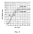
- Fig. 4 there is graphically illustrated a comparison of the performance of a typical single stage passenger gas generator and the two-stage gas generator according to the invention.
- Curve 100 in Fig. 4 shows the performance of a typical single stage passenger gas generator, that is, the rate at which the generator output pressure rises.
- Curve 102 shows the pressure rise rate of a physical embodiment of the two stage generator 10 according to the invention.
- the delay from the instant of initiation before the pressure begins to rise is shown by curve 102 to be about 4 milliseconds.
- the tank pressure, as shown by curve 102 is 7.54 PSIG, as compared to 11 PSIG for the typical gas generator as shown by curve 100.
- This initial relatively low pressure rise for the generator 10 occurs since the output pressure thereof during the initial 20 millisecond time frame is due, at least primarily, to the operation of the first stage only.
- Initiation of operation of the second stage of generator 10 at the end of the initial 20 millisecond time frame causes the tank pressure to rise at a steeper rate to produce a pressure of 27.75 PSIG at the end of 40 milliseconds. Thereafter, the rate of pressure rise gradually diminishes until at the end of 60 milliseconds the pressure is 36.5 pounds with maximum pressure of 39.85 PSIG occurring at 92.90 milliseconds from initiation.
- a two-stage gas generator in which the operation of the first stage is effective to provide rapid pressurization and release of inflation gas to an airbag and in which the operation of the second stage is effective to provide less rapid pressurization and release of inflation gas to the airbag, thereby increasing the delay time between the actuation of the two stages.
- a feature of the invention is the incorporation in the two-stage gas generator 10 of two methods for effecting delay in the initiation and operation of the second stage after initiation and operation of the first stage responsively to an incipient crash, the delays produced by these methods being accumulative.
- the first method involves the use of the delay body 20 and ball valve including ball 20, ball valve chamber 22, passageways 26 and 28 and delay foil 70 on the surface of delay body 20 for delaying the initiation in operation of the second stage.
- the second method for effecting a delay between the actuation of the two stages of generator 10 involves the use of the foil barrier 72 in engagement with the inside of wall 36 of housing 12 for delaying the breakout of hot gases from the second stage after ignition of the load of gas generant pellets 82 therein.
- no barrier of foil is provided on the inside of wall 36 of housing 12 in the first stage.
- the first stage is operative to begin delivery of gas to the airbag at a time sooner than it would if a barrier foil were provided on the inside of wall 36.
Landscapes
- Chemical & Material Sciences (AREA)
- Engineering & Computer Science (AREA)
- Mechanical Engineering (AREA)
- Organic Chemistry (AREA)
- Chemical Kinetics & Catalysis (AREA)
- Physics & Mathematics (AREA)
- Fluid Mechanics (AREA)
- Air Bags (AREA)
- Feeding, Discharge, Calcimining, Fusing, And Gas-Generation Devices (AREA)
Abstract
Description
- This invention relates to gas generators or inflators, and more particularly, to self-contained radial gas generators for inflating large passenger side occupant restraint airbags or crash bags where such generators utilize the combustion of solid gas generant compositions for the rapid generation of the inflating gas.
- Self-contained, single stage gas generators or inflators for automobile passenger side airbags that utilize combustible solid gas generant compositions are known in the prior art. A radial form of such generator is disclosed in U.S. Patent No. 4,296,084 that was issued on October 20, 1981 to G.V. Adams et al., which patent is assigned to the assignee of the present invention. The disclosure of patent 4,296,084, by reference, is incorporated herein. Common features of such generators are the inclusion in a single combustion chamber of a gas generant composition containing a pelletized alkali metal azide and means to filter and to cool the gas positioned between the gas generant composition and gas discharge orifices or outlet holes, as defined by the inflator housing. Such gas generant compositions are considered advantageous for use in automobile airbag inflating applications because the product of the combustion is mainly nitrogen, an inert gas. The speed of reaction or burning of such compositions may be selected to be such as to effect the generation of gas at a very rapid rate but without detonation.
- A problem has been encountered with single stage, that is, single combustion chamber, passenger side radial gas generators. The single combustion chamber passenger side radial generators known in the prior art tend to perform at an initial pressure rise rate which is greater than desirable in the zero to twenty (0 to 20) millisecond time frame after inflator initiation. The initial rapid pressure rise has been identified as a possible cause for injuries to an out-of-position occupant, and in particular, a child, during deployment of the airbag.
- In U.S. Patent No. 3,663,035 issued to Thomas W. Norton on May 16, 1972, there is disclosed a crash bag inflator comprising a two-stage gas generator, wherein a first stage is ignited to provide an initial deployment thrust at a time prior to ignition of a second stage. The two-stage gas generator, as described, consists of a pair of first and second inflators that are positioned in parallel relation, being held together by a tie bar. Each stage has one end attached to a block in which an ignition cavity common to both stages is provided. A fixed delay line operatively separates the second stage from the ignition cavity and delays ignition of the second stage by a few milliseconds. Both stages are said to be fully operative within less than ten (10) milliseconds of initiation by a pyrotechnic initiator responsively to a crash.
- While described as providing a more controlled delivery of gas to an airbag without disadvantageously delaying the deployment thereof, the Norton two-stage gas generator structure is complex and bulky and requires a volume of space larger than desirable for installation on the dashboard of an automotive vehicle.
- Thus, there is a need and a demand for improvement in passenger automotive restraint gas generators that have particular utility in protecting the out-of-position passenger and that are of maximum compactness, requiring a minimum volume of space for installation on the passenger side of an automotive vehicle. The present invention was devised to fill the technological gap that has existed in the art in this respect.
- An object of the invention is to provide an improved automotive restraint gas generator which features simplicity and efficiency in the construction thereof that enables economic manufacture and assembly, and that is operative to effect a controlled delivery of a gas for inflating a passenger side airbag for providing protection for the out-of-position passenger.
- Another object of the invention is to provide such an improved gas generator that is of maximum compactness and requires a minimum volume of space for installation in the dashboard of an automotive vehicle, on the passenger side thereof.
- A further object of the invention is to provide a two-stage automotive restraint gas generator in which operation of a first stage responsively to an incipient collision is utilized by means of a delay body and ball valve to effect delayed initiation of a second stage, with the ball valve effecting a subsequent operation to stop repressurization of the first stage and thereby separating the action of the two stages.
- Still another object of the invention is to provide such an improved two-stage gas generator in which the arrangement of the first stage is such as to provide rapid pressurization and release of inflation gas to the airbag and the arrangement of the second stage is such as to provide less rapid pressuriztion and release of inflation gas to the airbag thereby to increase the delay time between the actuations of the first and second stages.
- In accomplishing these and other objectives of the invention, there is provided an improved automotive restraint gas generator having particular utility for use on the passenger side of an automobile or similar vehicle. The gas generator comprises an inflator having first and second stages arranged in end-to-end relation in the same housing. Specifically, each stage is assembled into an individually associated chamber in an impact extruded lightweight housing which may be made of aluminum. A barrier or bulkhead positioned in suitably sealed relation at an intermediate location within the housing separates the two chambers. A ball valve in the bulkhead provides mechanical timing for ignition delay between firing of the two stages and for pressure control after ingition of both stages to prevent repressurizing the first stage.
- The improved generator is further characterized in that each stage includes suitable provisions for cooling and filtering and for maintaining a neutral or nonpropulsive thrust upon ignition.
- The various features of novelty which characterize the invention are pointed out with particularity in the claims annexed to and forming a part of this specification. For a better understanding of the invention, its operating advantages, and specific objects attained by its use, reference is made to the accompanying drawings and descriptive matter in which a preferred embodiment of the invention is illustrated.
- With this summary of the invention, a detailed description follows with reference being made to the accompanying drawings which form part of the specification, of which:
- Fig. 1 is a longitudinal view, partly in section, of the dual chamber passenger automotive restraint gas generator according to the invention;
- Fig. 2 is a plan view on an enlarged scale showing the bulkhead/ball valve of the gas generator of Fig. 1;
- Fig. 3 is a view from the left end of the bulkhead/ball valve of Fig. 2; and
- Fig. 4 is a graphic comparison of the pressure rise rate of a typical single-stage gas generator and the two-stage gas generator according to the present invention.
- An automotive restraint gas generator according to the invention is illustrated in Fig. 1 of the drawings. The gas generator, designated by the
reference numeral 10, includes a single impact extruded elongated tube orcylindrical housing 12. The extrusion process by which thehousing 12 is formed is known to those skilled in the art and consists of shaping by forcing the material of which the housing is made through suitable dies under pressure. The extrusion process per se forms no part of the present invention, and therefore, will not further described herein. -
Housing 12 preferably is made of aluminum and contains first and second elongatedcylindrical housing chambers perforated bulkhead 18, the outer periphery of thebulkhead 18 being suitably sealed by means (not shown) to the inner side of the wall ofhousing 12. Thechambers - Bulkhead 18, which is shown enlarged and in greater detail in Figs. 2 and 3, incorporates a ball valve comprising
delay body 20 having aball valve chamber 22 therein containing a ball 24. First andsecond passageways ball valve chamber 22 to thehousing chambers chamber 14 tochamber 16, resulting from a pressure differential therebetween, forces the ball 24 toward the adjacent end 28a ofpassageway 28 to restrict the gaseous flow intochamber 16, thus limiting any resulting diminishing of pressure incombustion chamber tube 46. Upon a reversal in that pressure differential, the resulting gaseous flow forces the ball 24 into engagement with avalve seat 30 on theadjacent end 26a ofpassageway 26 and thereby stops such flow. - The
housing 12 has afirst end 32 and asecond end 34 and includes acylindrical wall 36 in which a plurality of outlet orifices orholes 38 are formed.Holes 38 may be formed in two rows on each side of thehousing 12 along the length thereof, being positioned in uniformly spaced relation with respect to thehousing chambers holes 38 of each row on one side ofhousing 12 are spaced approximately 180° with respect to the holes of one of the rows on the other side thereof. Such positioning ofholes 38 inhousing wall 36 assures neutral thrust in the event of accidental ignition of thegenerator 10 during shipping and storage, thus precluding the possibility, upon such occurrence, of thegenerator 10 jumping and becoming a projectile. - The
ends housing 12 are closed in a sealing manner. Thus, thesecond end 34 ofhousing 12 is sealed by anend cap 40 which may be formed integrally therewith during the extrusion process. Anend cap base 42, which may be made of aluminum, may be inertia welded to thefirst end 32 of thehousing 12 in a manner described hereinafter. - Provided within the
first housing chamber 14, radially inwardly thereof and arranged concentrically therein, in the order named, are cylindrical outer cooling andfilter screens 44, a cylindrical perforated steelcombustion chamber tube 46, arupturable foil barrier 48 in engagement with the inner side of the wall oftube 46, an inner cylindricalcombustion chamber screen 50, and a centrally located cylindrical perforatedigniter tube 52 having arupturable foil tape 54 wrapped around the outside thereof. The cooling and filteringscreens 44 are positioned in surrounding relation to thecombustion chamber tube 46. Positioned in the elongated annular space between the innercombustion chamber screen 50 and theigniter tube 52 is a gas generant charge or load comprising uniformly distributedpellets 56. - The
foil barrier 48 and inner filteringscreen 50 are positioned in surrounding relation to the gasgenerant charge 56 andigniter tube 52. - Contained within the
igniter tube 52 is an elongated rapid detonating cord (RDC) fuze 58 which is surrounded by abooster charge 60 of igniter granules. The RDC fuze 58 is a high velocity ignition propagation cord that is manufactured by Teledyne McCormick Selph, 3601 Union Road, P. O. Box 6, Hollister, California 95024-0006. Thebooster charge 60 of igniter granules surrounding the RDC cord may comprise a mixture of 25% boron powder and 75% potassium nitrate. Thefoil tape 54 contains the igniter granules within the perforated igniter tube during manufacture. - In accordance with one embodiment of the invention, for a reason explained further hereinafter, the thickness of the
foil barrier 48 in engagement with the inner wall ofcombustion chamber tube 46 was selected to be 0.006 inches (0.015 centimeters). - The several enumerated components contained within the
housing chamber 14 comprise the first stage of thegas generator 10 and are held firmly against radial and endwise movement within thechamber 14 by an end cap andperforated tube holder 62 that is positioned at thefirst end 32 of thehousing 12 and by thedelay body 20 of thebulkhead 18. Specifically, aportion 64 of theholder 62 extends in close fitting or snug relation into one end of thecombustion chamber tube 46, and aportion 66 of thedelay body 20 extends in close fitting or snug relation into the other end thereof. Similarly, one end of theigniter tube 52 is snugly received within areceptacle 68 provided on theholder 62, centrally thereof, and the other end abuts against the surface ofportion 66 of thedelay body 20 with arupturable delay foil 70 interposed therebetween. Thedelay foil 70 provides a rupturable barrier to the flow of hot gases through thepassageway 26 from thecombustion chamber tube 46 and theigniter tube 52. - Provided within the
second housing chamber 16, radially inwardly thereof and arranged concentrically, in the order named, are arupturable foil barrier 72 on the inner side ofwall 36 ofhousing 12, cylindrical outer cooling and filter screens 74, a cylindrical perforated steelcombustion chamber tube 76, an inner cylindricalcombustion chamber screen 78, and a centrally located elongated cylindricalperforated igniter tube 80. Thefoil barrier 72 and the cooling andfiltering screens 74 are positioned in surrounding relation to thecombustion chamber tube 76. Positioned in the annular space between thecombustion chamber screen 78 and theigniter tube 80 is a gas generant charge or load comprising uniformly distributedpellets 82. Thefoil barrier 72 and the cooling andfiltering screens 74 are positioned in surrounding relation to thecombustion chamber tube 76. - Contained within the
igniter tube 80 is an elongated cast or extrudedbooster charge 84 which may comprise a mixture of 25% boron and 75% potassium nitrate. - The thickness of the
foil barrier 72 on the inner side ofwall 36 ofhousing 12 in the aforementioned embodiment of the invention was selected to be 0.004 inches (0.010 centimeters). - The several enumerated components within the
housing chamber 16 comprise the second stage of thegas generator 10 and are held firmly against radial and endwise movement within thechamber 16 by thedelay body 20 of thebulkhead 18 and by an end cap andtube locator 86 that is positioned in thehousing 12 at thesecond end 34 therof. Specifically, aportion 88 of thedelay body 20 extends in close fitting relation into one end of thecombustion chamber tube 76, and aportion 90 of the end cap andtube locator 86 extends in close fitting relation into the other end thereof. Also, one end ofigniter tube 80 is received within asuitable opening 92 in theportion 90 of end cap andtube locator 86 with the other end thereof positioned adjacent the end ofpassageway 28 indelay body 20. - An electrically actuatable initiator assembly 94, which may comprise a conventional electric squib, is mounted in the
end cap base 42 in sealing relation therewith and in alignment with the RDC fuze 58 at the adjacent end of theigniter tube 52. - The material of which the
gas generant pellets - As previously mentioned, the
end cap base 42 may be inertia welded to thefirst end 32 of thehousing 12. For facilitating the welding operation, theend cap base 42 includes acircular stub 42a that matches theend 32 ofhousing 12. - In the inertia welding operation, with the loaded
housing 12 mounted in a suitable tailstock fixture (not shown) and theend cap base 42 mounted in an aligned suitable headstock fixture (not shown), theend cap base 42 is rotated by power clutch means (not shown) to a speed which may be about 1930 revolutions per minute. Upon the attainment of such speed, the power clutch means is actuated to disconnect the power source and the freely spinningend cap base 42 is moved toward thehousing 12 to bring thecircular stub 42a into contact with thehousing end 32, with a force of about 630 pounds being applied. The resulting friction stops the spinning of theend cap base 42 in a fraction of a second but raises the temperature of the area sufficiently to cause consolidation thereat of the metal of thehousing 12 and theend cap base 42. Pressure is maintained for a short period, for example, a second or two, to allow the weld to solidify. Upon completion of the weld, acircular apron 42b that overlaps thecircular stub 42a may be rolled against the adjacent outer surface of thehousing 12 at theend 32 thereof to conceal the weld. - In the operation of the
gas generator 10, an electrical impulse from a crash sensor (not shown) fires the electrically actuatable initiator assembly 94. Firing of the assembly 94 results in ignition of the RDC fuze 58 which instantly sets off thebooster charge 60 of igniter granules along the entire length of theperforated igniter tube 52. Thefoil tape 54 wrapped around theigniter tube 52 not only contains the igniter granules during manufacture but also provides uniform ignition thereof. Specifically, upon ignition ofbooster charge 60, the pressure of the resulting gas builds up until a threshold value is reached at which thefoil tape 54 ruptures. This action promotes uniform ignition of the igniter granules prior to rupture and breakout of the hot gases produced by the ignitedbooster charge 60 into the load ofgas generant pellets 56 contained within the perforatedcombustion chamber tube 46. - Upon such initiation of combustion of the
gas generant pellets 56 in the perforatedcombustion chamber tube 46, the pressure of the resulting gas begins to rise until a peak is reached. The relativelythick foil barrier 48, which as noted hereinbefore is 0.006 inches thick, allows a rapid pressure build up. Prior to the attainment of peak pressure, however, during the combustion function time, the gas pressure reaches a threshold value at which thefoil barrier 48 ruptures. Upon such rupture, the material of thefoil barrier 48 is blown out of the way and the hot generated gas is allowed to flow through a plurality ofholes 96 in the wall ofcombustion chamber tube 46, such gas flow being cleaned, that is, filtered, of solid particles of combustion by the innercombustion chamber screen 50.Holes 96 in thecombustion chamber tube 46 preferably are provided in two rows on each side spaced along the length thereof, with the rows ofholes 96 on both sides offset by approximately 90° from the rows ofholes 38 in thewall 36 ofhousing 12. - The hot generated gas released through the
holes 96 passes around and through the outer cooling andfilter screens 44 and immediately through theholes 38 in thewall 36 ofhousing 12 into an air bag (not shown) to be inflated. - At the same time the hot generated gas under pressure in the
combustion chamber tube 46 ruptures and breaks through thedelay foil 70 on the surface of theportion 66 of thedelay body 20. The hot gas then passes in sequence through thepassageway 26, theball valve chamber 22, and thepassageway 28. An initial rush of such hot gas through thebulkhead 18 into the second stage of thegenerator 10 is quickly diminished due to movement of the ball 24 against the adjacent opening ofpassgeway 28. Such flow of hot gas sets off thebooster charge 84 in theigniter tube 80 along the entire length thereof thereby to produce ignition of thegas generant pellets 82 in the perforatedcombustion chamber tube 76. Upon ignition of thegas generant pellets 82, the pressure of the resulting gas begins to rise. Prior to the attainment of peak pressure, however, during the combustion fucntion time, the gas pressure reaches a threshold value at which thefoil barrier 72 on the inside ofwall 36 ofhousing 12 ruptures. - Upon rupture of the
barrier foil 72, the hot generated gas produced in thecombustion chamber tube 76 is released and delivered to the airbag (not shown) through a plurality ofholes 98 in the wall oftube 76, such gas being released immediately without encountering any further barriers although having to pass in sequence through the innercombustion chamber screen 78 for filtering and through the outer cooling andfiltering screens 74 for cooling and additional filtering. - At the same time, the pressurization of the gases in the second stage forces the ball 24 of the delay body and ball valve to reverse, that is, to move through the
ball valve chamber 22 into engagement with theball valve seat 30 at the end ofpassageway 26. This cuts off the flow of gas from the second stage into the first stage and thus stops repressurization of the first stage, and makes the action that of two separate gas generators with a delay time between the two, in one embodiment of the invention, being approximately 15 milliseconds. Abarrier foil 72 having a thickness of 0.004 inches, which is less than that of thebarrier foil 48 in the first stage, is selected so that the rupture thereof to effect release of the gas to an airbag occurs when the pressure in the two stages are approximately equal, thereby balancing the pressures of the two stages. - In Fig. 4 there is graphically illustrated a comparison of the performance of a typical single stage passenger gas generator and the two-stage gas generator according to the invention.
Curve 100 in Fig. 4 shows the performance of a typical single stage passenger gas generator, that is, the rate at which the generator output pressure rises.Curve 102 shows the pressure rise rate of a physical embodiment of the twostage generator 10 according to the invention. - As shown by
curve 100 of Fig. 4, there is a delay of about 9 milliseconds from the instant of gas generator initiation (represented by the intersection of the horizontal and vertical axes of the graph) before the pressure begins to rise in the single stage generator. In the next 11 milliseconds the pressure rise rate is seen to be very steep, resulting in a "TANK" or airbag pressure in a 100 liter tank of about 11 pounds per square inch gauge (PSIG) 20 milliseconds after initiation. The pressure rise rate continues to be very steep, although moderating somewhat at 40 milliseconds from initiation, resulting in a maximum pressure of almost 40 PSIG at 60 milliseconds from initiation. - In the two-
stage gas generator 10, according to the invention, the delay from the instant of initiation before the pressure begins to rise is shown bycurve 102 to be about 4 milliseconds. At the end of 20 milliseconds from initiation, the tank pressure, as shown bycurve 102, is 7.54 PSIG, as compared to 11 PSIG for the typical gas generator as shown bycurve 100. This initial relatively low pressure rise for thegenerator 10 occurs since the output pressure thereof during the initial 20 millisecond time frame is due, at least primarily, to the operation of the first stage only. - Initiation of operation of the second stage of
generator 10 at the end of the initial 20 millisecond time frame causes the tank pressure to rise at a steeper rate to produce a pressure of 27.75 PSIG at the end of 40 milliseconds. Thereafter, the rate of pressure rise gradually diminishes until at the end of 60 milliseconds the pressure is 36.5 pounds with maximum pressure of 39.85 PSIG occurring at 92.90 milliseconds from initiation. - Thus, in accordance with the invention, there is provided a two-stage gas generator in which the operation of the first stage is effective to provide rapid pressurization and release of inflation gas to an airbag and in which the operation of the second stage is effective to provide less rapid pressurization and release of inflation gas to the airbag, thereby increasing the delay time between the actuation of the two stages.
- A feature of the invention is the incorporation in the two-
stage gas generator 10 of two methods for effecting delay in the initiation and operation of the second stage after initiation and operation of the first stage responsively to an incipient crash, the delays produced by these methods being accumulative. The first method involves the use of thedelay body 20 and ballvalve including ball 20,ball valve chamber 22,passageways foil 70 on the surface ofdelay body 20 for delaying the initiation in operation of the second stage. - The second method for effecting a delay between the actuation of the two stages of
generator 10 involves the use of thefoil barrier 72 in engagement with the inside ofwall 36 ofhousing 12 for delaying the breakout of hot gases from the second stage after ignition of the load ofgas generant pellets 82 therein. As noted, no barrier of foil is provided on the inside ofwall 36 ofhousing 12 in the first stage. As a result, there is a fast breakout of hot gases from the first stage throughholes 38 inwall 36 upon rupture of thefoil barrier 48 in engagement with the inside of the wall of thecombustion chamber tube 46. Thus, the first stage is operative to begin delivery of gas to the airbag at a time sooner than it would if a barrier foil were provided on the inside ofwall 36. The subsequent pressurization of the second stage following initiation thereof by the gas flow through theball valve passages ball valve seat 30. This stops repressurization of the first stage and makes the action of the two stages that of two separate gas generators with a delay time between the two of approximately 15 milliseconds. - Other features of the invention comprise:
- (a) The use of a lightweight aluminum housing together with a combination of components that lend themselves to economical manufacture and ease of assembly therein.
- (b) The bulkhead/ball valve structure provides mechanical timing for ignition delay between the first and second stages of the gas generator and pressure control after ignition of the second stage to prevent repressurization of the first stage.
- (c) The provisions made for gas diversion for cooling and filtering and the maintenance of a neutral thrust unit.
- (d) The cast or extruded boron nitrate booster charge in the igniter for the second stage of the
generator 10 eliminates the need therein for igniter granules and an igniter fuze. Also eliminated is the need for an aluminum foil to retain the igniter granules. - With this description of the invention in detail, those skilled in the art will appreciate that modifications may be made to the invention without departing from its spirit. Therefore, it is not intended that the scope of the invention be limited to the specific embodiments illustrated and described. Rather, it is intended that the scope of the invention be determined by the appended claims and their equivalents.
Claims (11)
a single impact extruded perforated elongated housing (12) having a first end (32) and a second end (34),
an end cap base (42) enclosing said first end of said housing,
an end cap (40) enclosing said second end of said housing,
a perforated bulkhead (18) positioned at an intermediate location within said housing, said bulkhead forming first and second elongated chambers (14, 16) within said housing and having formed therein a ball valve including a ball valve chamber (22) and first and second passageways (26, 28) connecting said ball valve chamber to said first and second elongated chambers, respectively, said ball valve chamber having a ball (24) therein that is movable into operative relation with respect to said first and second passageways for controlling any flow of gas through said bulkhead tending to result from a difference in gas pressures within said first and second elongated chambers,
first and second elongated gas generating charges (56, 82) of solid pyrotechnic material contained in said first and second elongated chambers (14, 16), respectively,
first and second elongated perforated igniter tubes (52, 80) provided in operative relation with said first and second elongated gas generating charges (56, 82), respectively, each of said perforated igniter tubes having a first end and a second end, and
an initiator (94) provided in operative relation with one only of said perforated igniter tubes (52, 80).
wherein said initiator (94) is provided in operative relation with said first gas generating charge (56).
wherein said perforated elongated housing (12) has a cylindrical wall (32) with a plurality of outlet holes (38) formed therein along the length thereof in at least two rows on each of the opposite sides of said housing, and further including
first and second elongated perforated combustion chamber tubes (46, 76) each of which has a first end and a second end and an inner wall,
first and second elongated filter screens (50, 78),
first and second elongated rupturable foil barriers (48, 72),
first and second elongated cooling and filter screens (44, 74) each of which has a first end and a second end,
wherein said first and second elongated gas generating charges (56, 82) are contained within said first and second combustion chamber tubes (46, 76), respectively,
wherein said first and second filter screens (50, 78) are provided in surrounding relation to said first and second gas generating charges, respectively, within the respectively associated perforated combustion chamber tube,
wherein said first foil barrier (48) is provided in surrounding relation to said filter screen (50) and gas generating charge (56) in said first perforated combustion chamber tube (46),
wherein said first and second elongated cooling and filter screens (44, 74) are provided in surrounding relation to said first and second combustion chamber tubes (46, 76), respectively, and
wherein said second foil barrier (72) is provided in surrounding relation to said second cooling and filter screens (74).
an end cap and tube holder (62) positioned at the first end (32) of said elongated housing,
an end cap and tube locator (86) positioned at the second end (34) of said elongated housing, and
a rupturable elongated third foil barrier (70),
said end cap and tube holder having a projecting portion (64) that extends into said first end of said first perforated combustion chamber tube (46),
said bulkhead (18) having a first portion (66) thereon that extends in snug relation into said second end of said first perforated combustion chamber tube,
said third foil barrier (70) being positioned in operative relation with said first portion (66) of said bulkhead to normally preclude the flow of gas through said first passageway (26),
said end cap and tube holder (62) having a receptacle (68) thereon that receives and locates the first end of said first perforated igniter tube (52),
said second end of said first perforated igniter tube being positioned in abutting relation with said first portion of said bulkhead with said third foil barrier interposed therebetween,
said end cap and tube locator (86) having a projecting portion (90) that extends in snug relation into said second end of said second perforated combustion chamber tube (76),
said bulkhead having a second portion (88) thereon that extends in snug relation into said first end of said second perforated combustion chamber tube (76), and
said end cap and tube locator (86) having a receptacle (92) on said projecting portion (90) thereof for receiving and locating said second end of said second perforated igniter tube (80).
wherein said end cap and tube locator (86) includes another portion that retains the second end of said second cooling and filter screens (74) with the first end of said of said second cooling and filter screens positioned in abutting relation with said bulkhead (18).
Applications Claiming Priority (2)
| Application Number | Priority Date | Filing Date | Title |
|---|---|---|---|
| US07/369,874 US4950458A (en) | 1989-06-22 | 1989-06-22 | Passenger automotive restraint generator |
| US369874 | 1989-06-22 |
Publications (3)
| Publication Number | Publication Date |
|---|---|
| EP0404572A2 true EP0404572A2 (en) | 1990-12-27 |
| EP0404572A3 EP0404572A3 (en) | 1991-08-14 |
| EP0404572B1 EP0404572B1 (en) | 1994-05-18 |
Family
ID=23457278
Family Applications (1)
| Application Number | Title | Priority Date | Filing Date |
|---|---|---|---|
| EP90306800A Expired - Lifetime EP0404572B1 (en) | 1989-06-22 | 1990-06-21 | Passenger automotive restraint generator |
Country Status (9)
| Country | Link |
|---|---|
| US (1) | US4950458A (en) |
| EP (1) | EP0404572B1 (en) |
| JP (1) | JPH0659812B2 (en) |
| KR (1) | KR920007843B1 (en) |
| AU (1) | AU626052B2 (en) |
| CA (1) | CA2018043C (en) |
| DE (1) | DE69008932T2 (en) |
| ES (1) | ES2056384T3 (en) |
| MX (1) | MX172820B (en) |
Cited By (10)
| Publication number | Priority date | Publication date | Assignee | Title |
|---|---|---|---|---|
| EP0496488A1 (en) * | 1991-01-22 | 1992-07-29 | Morton International, Inc. | Flash ignition system |
| EP0849131A1 (en) | 1996-12-18 | 1998-06-24 | S.n.c. Livbag | Pyrotechnic tubular integral gas generator for airbags |
| EP0849130A1 (en) | 1996-12-18 | 1998-06-24 | S.n.c. Livbag | Pyrotechnic gas generator with composite loading |
| DE19654315A1 (en) * | 1996-12-24 | 1998-06-25 | Dynamit Nobel Ag | Hybrid gas generator |
| US5799973A (en) * | 1995-04-22 | 1998-09-01 | Temic Bayern-Chemie Airbag Gmbh | Pyrotechnic gas generator with two separate combustion chambers |
| US5804758A (en) * | 1995-08-04 | 1998-09-08 | Snc Livbag | Pyrotechnic hot-gas generator for side protection bag |
| DE19728438A1 (en) * | 1997-07-03 | 1999-01-07 | Temic Bayern Chem Airbag Gmbh | Pyrotechnic gas generator |
| EP0867347A3 (en) * | 1997-03-24 | 1999-11-10 | Daicel Chemical Industries, Ltd. | Gas generating pellets, gas generator and air bag apparatus |
| EP0926015A3 (en) * | 1997-12-26 | 2000-05-24 | Daicel Chemical Industries, Ltd. | An airbag gas generator and an airbag apparatus |
| US6562161B1 (en) | 1997-03-24 | 2003-05-13 | Daicel Chemical Industries, Ltd. | Gas generating compositions for air bag |
Families Citing this family (123)
| Publication number | Priority date | Publication date | Assignee | Title |
|---|---|---|---|---|
| US4941678A (en) * | 1989-06-29 | 1990-07-17 | Morton Thiokol, Inc. | Lightweight reaction can for passenger inflators |
| US5033390A (en) * | 1989-11-13 | 1991-07-23 | Morton International, Inc. | Trilevel performance gas generator |
| SE463580B (en) * | 1989-11-21 | 1990-12-10 | Saab Missiles Ab | PROJECTIL MAKES DISTRIBUTION OF A LOAD WITH TIME DELAY |
| US5286054A (en) * | 1989-12-04 | 1994-02-15 | Talley Automotive Products, Inc. | Aspirating/venting motor vehicle passenger airbag module |
| JP3070132B2 (en) | 1991-05-23 | 2000-07-24 | 日本工機株式会社 | Gas generator for airbag deployment |
| US5320382A (en) * | 1991-05-31 | 1994-06-14 | Gt-Devices | Pulsed pressure source particularly adapted for vehicle occupant air bag restraint systems |
| US5397544A (en) * | 1991-11-14 | 1995-03-14 | Nippon Koki Co., Ltd | Air bag inflation gas generator |
| JPH05185899A (en) * | 1992-01-10 | 1993-07-27 | Takata Kk | Inflator of air bag device |
| US5509686A (en) * | 1992-05-04 | 1996-04-23 | General Motors Corporation | Inflatable restraint system with gas augmentation |
| US5269561A (en) * | 1992-07-06 | 1993-12-14 | Morton International, Inc. | Vented gas passenger side air bag inflator |
| US5221109A (en) * | 1992-07-23 | 1993-06-22 | Morton International, Inc. | Airbag inflator having vents to terminate inflation |
| US5443286A (en) * | 1992-10-09 | 1995-08-22 | Morton International, Inc. | Gas generator for vehicle occupant restraint system |
| US5409259A (en) * | 1992-10-09 | 1995-04-25 | Morton International, Inc. | Gas generator for vehicle occupant restraint system |
| JP3082474B2 (en) * | 1992-10-30 | 2000-08-28 | タカタ株式会社 | Airbag device |
| US5441515A (en) * | 1993-04-23 | 1995-08-15 | Advanced Cardiovascular Systems, Inc. | Ratcheting stent |
| US5388322A (en) * | 1993-05-28 | 1995-02-14 | Simon; Joseph A. | Method of making a shatterproof air bag inflator pressure vessel |
| JPH079939A (en) * | 1993-06-22 | 1995-01-13 | Nippon Koki Kk | Gas generator for airbag deployment |
| DE4324554B4 (en) * | 1993-07-22 | 2006-03-02 | Delphi Technologies, Inc. (n.d.Ges.d. Staates Delaware), Troy | Gas generator, in particular for an airbag |
| US5481977A (en) * | 1993-07-30 | 1996-01-09 | Alliedsignal Inc. | Work-controlled launching device with accumulator |
| US5682014A (en) * | 1993-08-02 | 1997-10-28 | Thiokol Corporation | Bitetrazoleamine gas generant compositions |
| US5454593A (en) * | 1993-08-02 | 1995-10-03 | Morton International, Inc. | Metal igniter tube boot with permanent retention system |
| US5472647A (en) * | 1993-08-02 | 1995-12-05 | Thiokol Corporation | Method for preparing anhydrous tetrazole gas generant compositions |
| US5429691A (en) | 1993-08-10 | 1995-07-04 | Thiokol Corporation | Thermite compositions for use as gas generants comprising basic metal carbonates and/or basic metal nitrates |
| US5401340A (en) | 1993-08-10 | 1995-03-28 | Thiokol Corporation | Borohydride fuels in gas generant compositions |
| US5439537A (en) | 1993-08-10 | 1995-08-08 | Thiokol Corporation | Thermite compositions for use as gas generants |
| DE9312093U1 (en) * | 1993-08-13 | 1993-10-28 | Temic Bayern-Chemie Airbag Gmbh, 84544 Aschau | Support for flat elements |
| JPH0769164A (en) * | 1993-09-01 | 1995-03-14 | Takata Kk | Inflator for air bag device |
| US5695216A (en) * | 1993-09-28 | 1997-12-09 | Bofors Explosives Ab | Airbag device and propellant for airbags |
| EP0740645B1 (en) | 1994-01-19 | 2012-08-22 | Alliant Techsystems Inc. | Metal complexes for use as gas generants |
| US6969435B1 (en) | 1994-01-19 | 2005-11-29 | Alliant Techsystems Inc. | Metal complexes for use as gas generants |
| US5725699A (en) | 1994-01-19 | 1998-03-10 | Thiokol Corporation | Metal complexes for use as gas generants |
| US20050067074A1 (en) | 1994-01-19 | 2005-03-31 | Hinshaw Jerald C. | Metal complexes for use as gas generants |
| JPH07215162A (en) * | 1994-01-27 | 1995-08-15 | Daicel Chem Ind Ltd | Gas generator for air bag |
| US5441705A (en) * | 1994-03-14 | 1995-08-15 | Morton International, Inc. | Combined reaction can and inflator with extruded generant |
| US5387008A (en) * | 1994-03-14 | 1995-02-07 | Morton International, Inc. | Generant preload and tolerance takeup assembly for vehicular airbag installation |
| US5513879A (en) * | 1994-05-04 | 1996-05-07 | Breed Automotive Technology, Inc. | Two stage inflator with module venting for passenger side airbags |
| US5551723A (en) * | 1994-07-20 | 1996-09-03 | Breed Automotive Technology, Inc. | Pulse shaping for airbag inflators |
| US5507520A (en) * | 1994-12-16 | 1996-04-16 | Trw Vehicle Safety Systems Inc. | Air bag inflator and method of assembly |
| US5564743A (en) * | 1995-03-22 | 1996-10-15 | Morton International, Inc. | Multiple stage air bag inflator system |
| US5529334A (en) * | 1995-05-08 | 1996-06-25 | Trw Vehicle Safety Systems Inc. | Air bag inflator and method of assembly |
| DE19520847B4 (en) * | 1995-06-08 | 2005-08-18 | Honda Giken Kogyo K.K. | Device for generating gas for a motor vehicle airbag |
| US5628528A (en) * | 1995-07-06 | 1997-05-13 | Automotive Systems Laboratory, Inc. | Dual chamber nonazide gas generator |
| US5564738A (en) * | 1995-08-10 | 1996-10-15 | Morton International, Inc. | Overflow channeling reaction canister assembly |
| US5622380A (en) * | 1995-09-21 | 1997-04-22 | Automotive Systems Laboratory, Inc. | Variable nonazide gas generator having multiple propellant chambers |
| DE19541583A1 (en) * | 1995-11-08 | 1997-05-15 | Temic Bayern Chem Airbag Gmbh | Gas generator |
| US5833264A (en) * | 1995-11-10 | 1998-11-10 | Honda Giken Kogyo Kabushiki Kaisha | Inflator assembly for a vehicle air bag system |
| DE19541924A1 (en) * | 1995-11-10 | 1997-05-15 | Diehl Gmbh & Co | Two stage gas generator for vehicle occupant safety airbag |
| US5611567A (en) * | 1995-12-18 | 1997-03-18 | Cartridge Actuated Devices, Inc. | Non-explosive linear release device |
| US5700030A (en) * | 1995-12-27 | 1997-12-23 | Trw Vehicle Safety Systems Inc. | Inflator with combustion chamber pressure regulator |
| US5630619A (en) * | 1996-02-28 | 1997-05-20 | Morton International, Inc. | Hybrid adaptive inflator for airbags |
| US5593181A (en) * | 1996-03-15 | 1997-01-14 | Morton International, Inc. | Generant wafer core ignition system for passenger side airbag inflator |
| US5704640A (en) * | 1996-05-01 | 1998-01-06 | Morton International, Inc. | Bondable autoignition foil |
| FR2760710B1 (en) * | 1997-03-14 | 1999-04-23 | Livbag Snc | PYROTECHNICAL GAS GENERATOR WITH ADAPTABLE FLOW AND VOLUME FOR PROTECTIVE CUSHIONS |
| US5984351A (en) * | 1997-04-11 | 1999-11-16 | Autoliv Asp, Inc. | Dual stage actuation system |
| DE69835077T3 (en) * | 1997-09-08 | 2012-01-26 | Zodiac Automotive Us Inc. | INFLATION DEVICE WITH DISTRIBUTED CHARGE |
| DE69909369T2 (en) | 1998-05-20 | 2004-02-12 | Takata Corp. | Airbag device with a two-stage ignition technology |
| JP3820795B2 (en) * | 1998-05-20 | 2006-09-13 | タカタ株式会社 | Airbag device |
| JPH11334518A (en) * | 1998-05-29 | 1999-12-07 | Takata Kk | Inflator and air bag device |
| US6412815B1 (en) | 1998-09-28 | 2002-07-02 | Daicel Chemical Industries, Ltd. | Gas generator for air bag and air bag device |
| ATE526209T1 (en) | 1998-09-28 | 2011-10-15 | Daicel Chem | GAS GENERATOR FOR AN AIRBAG AND AIRBAG |
| US6039348A (en) * | 1998-10-09 | 2000-03-21 | General Motors Corporation | Variable output inflator with adaptive heat sinking |
| US6176517B1 (en) * | 1998-10-23 | 2001-01-23 | Autoliv Aspinc. | Gas generating apparatus |
| JP3220443B2 (en) | 1998-11-30 | 2001-10-22 | ダイセル化学工業株式会社 | Gas generator for airbag and airbag device |
| WO2000048868A1 (en) | 1999-02-16 | 2000-08-24 | Daicel Chemical Industries, Ltd. | Gas generator for multi-stage air bag and air bag device |
| US6547277B1 (en) * | 1999-02-26 | 2003-04-15 | Automotive Systems Laboratory, Inc. | Two chamber gas generator |
| DE10006522B4 (en) | 1999-03-05 | 2018-02-01 | Trw Vehicle Safety Systems Inc. | Inflator for a two-stage airbag |
| US6701849B2 (en) | 1999-03-05 | 2004-03-09 | Trw Inc. | Dual stage air bag inflator with secondary propellant cap |
| WO2000068043A1 (en) | 1999-05-11 | 2000-11-16 | Automotive Systems Laboratory, Inc. | Dual chamber inflator |
| US6142519A (en) * | 1999-09-01 | 2000-11-07 | Autoliv Asp, Inc. | Inflation assembly |
| TW469235B (en) * | 1999-10-04 | 2001-12-21 | Daicel Chem | Gas generator for air bag and air bag device |
| US7188567B1 (en) | 1999-11-12 | 2007-03-13 | Zodiac Automotive Us Inc. | Gas generation system |
| TW527294B (en) * | 1999-11-29 | 2003-04-11 | Daicel Chem | Gas generator for air bag and devices for the same |
| US6189927B1 (en) | 1999-12-16 | 2001-02-20 | Autoliv Asp, Inc. | Adaptive output inflator |
| US6659500B2 (en) | 2000-05-11 | 2003-12-09 | Automotive Systems Laboratory, Inc. | Multi-chamber inflator |
| TW521052B (en) * | 2000-12-27 | 2003-02-21 | Daicel Chem | Air bag gas generator and air bag device |
| JP2003034219A (en) | 2001-07-19 | 2003-02-04 | Daicel Chem Ind Ltd | Gas generator and airbag device for airbag |
| KR100471476B1 (en) * | 2001-12-20 | 2005-03-08 | 현대자동차주식회사 | Dual stage inflator for air bag |
| US6948737B2 (en) * | 2001-12-26 | 2005-09-27 | Daicel Chemical Industries, Ltd. | Gas generator for air bag |
| JP4215163B2 (en) | 2002-01-03 | 2009-01-28 | オートモーティブ システムズ ラボラトリー インコーポレーテッド | Air bag inflator |
| JP2005521582A (en) * | 2002-03-26 | 2005-07-21 | オートモーティブ システムズ ラボラトリー インコーポレーテッド | 2-stage inflator with multiple chambers |
| US6997477B2 (en) * | 2002-04-19 | 2006-02-14 | Automotive Systems Laboratory, Inc. | Inflator |
| US7162958B2 (en) * | 2002-05-17 | 2007-01-16 | Zodiac Automotive Us Inc. | Distributed charge inflator system |
| US6886469B2 (en) * | 2002-05-17 | 2005-05-03 | Zodiac Automotive Us Inc. | Distributed charge inflator system |
| US7137341B2 (en) * | 2002-05-17 | 2006-11-21 | Zodiac Automotive Us Inc. | Distributed charge inflator system |
| DE20219898U1 (en) * | 2002-12-23 | 2003-04-30 | TRW Airbag Systems GmbH, 84544 Aschau | inflator |
| US6976704B2 (en) * | 2003-01-30 | 2005-12-20 | Autoliv Asp, Inc. | Adaptive output airbag inflation device |
| DE20303836U1 (en) * | 2003-03-11 | 2003-07-24 | TRW Airbag Systems GmbH, 84544 Aschau | Inflator for a vehicle occupant restraint system |
| DE20304249U1 (en) * | 2003-03-17 | 2003-07-31 | TRW Airbag Systems GmbH, 84544 Aschau | Inflator for a vehicle occupant restraint system |
| US7131238B2 (en) * | 2003-07-21 | 2006-11-07 | Fm Global Technologies, Llc | Method of testing seismic braces |
| US7192055B2 (en) * | 2003-11-13 | 2007-03-20 | Automotive Systems Laboratory, Inc. | Pyrotechnic linear inflator |
| US7243946B2 (en) * | 2003-11-18 | 2007-07-17 | Automotive Systems Laboratory, Inc. | Peroxide linear inflator |
| US7080854B2 (en) * | 2004-01-13 | 2006-07-25 | Automotive Systems Laboratory, Inc. | Pyrotechnic linear inflator |
| US7404571B2 (en) * | 2004-02-26 | 2008-07-29 | Automotive Systems Laboratory, Inc. | Linear inflator and mounting clip |
| US20050200103A1 (en) * | 2004-02-27 | 2005-09-15 | Burns Sean P. | Pyrotechnic linear inflator with structural enhancement |
| US7267365B2 (en) * | 2004-03-10 | 2007-09-11 | Automotive Systems Laboratory, Inc. | Inflator |
| US7789018B2 (en) * | 2004-04-02 | 2010-09-07 | Automotive Systems Laboratory, Inc. | Gas generator assembly |
| US7293798B2 (en) * | 2004-04-05 | 2007-11-13 | Automotive Systems Laboratory, Inc. | Pyrotechnic linear inflator |
| US7367584B2 (en) * | 2004-04-19 | 2008-05-06 | Automotive Systems Laboratory, Inc. | Gas generating system |
| US7343862B2 (en) * | 2004-05-27 | 2008-03-18 | Automotive Systems Laboratory, Inc. | Gas generating system |
| US7438315B2 (en) * | 2004-05-28 | 2008-10-21 | Automotive Systems Laboratory, Inc. | Inflator and method of assembly |
| US7814838B2 (en) * | 2004-06-28 | 2010-10-19 | Automotive Systems, Laboratory, Inc. | Gas generating system |
| US7275760B2 (en) * | 2004-07-23 | 2007-10-02 | Automotive Systems Laboratory, Inc. | Multi-chamber gas generating system |
| US8622419B2 (en) * | 2004-07-27 | 2014-01-07 | Automotive Systems Laboratory, Inc. | Vehicle component with integral inflator |
| US7237801B2 (en) * | 2004-08-31 | 2007-07-03 | Automotive Systems Laboratory, Inc. | Gas generating system |
| WO2006078819A2 (en) * | 2005-01-20 | 2006-07-27 | Automotive Systems Laboratory, Inc. | Flexible gas generator |
| US7537240B2 (en) * | 2005-02-22 | 2009-05-26 | Automotive Systems Laboratory, Inc. | Gas generating system |
| US7654565B2 (en) * | 2005-06-02 | 2010-02-02 | Automotive Systems Laboratory, Inc. | Gas generating system |
| DE112006001781T5 (en) | 2005-06-30 | 2008-05-08 | Automotive Systems Laboratory, Inc., Armada | gas generator |
| US7770923B2 (en) * | 2005-08-10 | 2010-08-10 | Dae Ah Tech Co., Ltd. | Structure of inflater inside cylinder for air bag for vehicle |
| KR100730757B1 (en) | 2005-08-10 | 2007-06-20 | (주) 대아테크 | Inflator inner structure of automobile airbag |
| CN100572149C (en) * | 2005-08-10 | 2009-12-23 | 株式会社大亚特 | The structure of the inner cylinder of the inflator used for the air bag of the vehicle |
| US7806954B2 (en) * | 2005-11-01 | 2010-10-05 | Automotive Systems Laboratory Inc. | Gas generator |
| US8376400B2 (en) | 2006-04-21 | 2013-02-19 | Tk Holdings, Inc. | Gas generating system |
| FR2905918B1 (en) * | 2006-09-20 | 2009-04-17 | Livbag Soc Par Actions Simplif | "PYROTECHNIC GENERATOR WITH TWO COMBUSTION CHAMBERS SEPARATED BY A TUYERE" |
| IL184216A0 (en) * | 2007-06-25 | 2008-01-06 | Rafael Advanced Defense Sys | Two-stage airbag inflation system with pyrotechnic delay |
| DE102007037325B4 (en) * | 2007-08-08 | 2013-11-14 | Trw Airbag Systems Gmbh | inflator |
| US7950691B1 (en) | 2007-10-31 | 2011-05-31 | Tk Holdings, Inc. | Inflator body with adapter form end |
| FR2937295B1 (en) * | 2008-10-17 | 2010-12-31 | Livbag | PYROTECHNIC GAS GENERATOR WITH THERMAL BRIDGE |
| JP5667367B2 (en) * | 2009-03-06 | 2015-02-12 | オートリブ エー・エス・ピー・インク | Air bag apparatus and gas generator used therefor |
| FR2959006A1 (en) | 2010-04-20 | 2011-10-21 | Livbag | GENERATOR OF GAS WITH TWO PYROTECHNIC LOADS |
| US8827308B1 (en) | 2013-03-15 | 2014-09-09 | Autoliv Asp, Inc. | Filter with integrated baffle |
| JP6543560B2 (en) | 2015-11-26 | 2019-07-10 | 株式会社ダイセル | Gas generator |
| JP6695365B2 (en) * | 2018-01-25 | 2020-05-20 | 本田技研工業株式会社 | High pressure tank structure |
Family Cites Families (5)
| Publication number | Priority date | Publication date | Assignee | Title |
|---|---|---|---|---|
| US4213635A (en) * | 1978-11-13 | 1980-07-22 | Toyota Kodosha Kogyo Kabushiki Kaisha | Two-stage air bag system |
| US4358998A (en) * | 1980-02-04 | 1982-11-16 | Thiokol Corporation | Igniter for a pyrotechnic gas bag inflator |
| US4817828A (en) * | 1986-10-03 | 1989-04-04 | Trw Automotive Products Inc. | Inflatable restraint system |
| US4943086A (en) * | 1989-06-30 | 1990-07-24 | Morton Thiokol, Inc. | Gas bag inflator with a two welded joint housing |
| CN106611593A (en) | 2015-10-22 | 2017-05-03 | 小米科技有限责任公司 | Content display method and device |
-
1989
- 1989-06-22 US US07/369,874 patent/US4950458A/en not_active Expired - Lifetime
-
1990
- 1990-06-01 CA CA002018043A patent/CA2018043C/en not_active Expired - Lifetime
- 1990-06-13 MX MX021142A patent/MX172820B/en unknown
- 1990-06-19 AU AU57586/90A patent/AU626052B2/en not_active Ceased
- 1990-06-21 JP JP2161464A patent/JPH0659812B2/en not_active Expired - Fee Related
- 1990-06-21 EP EP90306800A patent/EP0404572B1/en not_active Expired - Lifetime
- 1990-06-21 ES ES90306800T patent/ES2056384T3/en not_active Expired - Lifetime
- 1990-06-21 DE DE69008932T patent/DE69008932T2/en not_active Expired - Fee Related
- 1990-06-22 KR KR1019900009554A patent/KR920007843B1/en not_active Expired
Cited By (14)
| Publication number | Priority date | Publication date | Assignee | Title |
|---|---|---|---|---|
| EP0496488A1 (en) * | 1991-01-22 | 1992-07-29 | Morton International, Inc. | Flash ignition system |
| US5799973A (en) * | 1995-04-22 | 1998-09-01 | Temic Bayern-Chemie Airbag Gmbh | Pyrotechnic gas generator with two separate combustion chambers |
| US5804758A (en) * | 1995-08-04 | 1998-09-08 | Snc Livbag | Pyrotechnic hot-gas generator for side protection bag |
| US6490978B1 (en) | 1996-12-18 | 2002-12-10 | Livbag, S.N.C. | Pyrotechnic gas generator with plastic bonded charge |
| EP0849131A1 (en) | 1996-12-18 | 1998-06-24 | S.n.c. Livbag | Pyrotechnic tubular integral gas generator for airbags |
| EP0849130A1 (en) | 1996-12-18 | 1998-06-24 | S.n.c. Livbag | Pyrotechnic gas generator with composite loading |
| US6029994A (en) * | 1996-12-18 | 2000-02-29 | Livbag S.N.C. | Integral tubular generator for inflating protective cushions |
| DE19654315A1 (en) * | 1996-12-24 | 1998-06-25 | Dynamit Nobel Ag | Hybrid gas generator |
| EP0867347A3 (en) * | 1997-03-24 | 1999-11-10 | Daicel Chemical Industries, Ltd. | Gas generating pellets, gas generator and air bag apparatus |
| US6562161B1 (en) | 1997-03-24 | 2003-05-13 | Daicel Chemical Industries, Ltd. | Gas generating compositions for air bag |
| DE19728438A1 (en) * | 1997-07-03 | 1999-01-07 | Temic Bayern Chem Airbag Gmbh | Pyrotechnic gas generator |
| US6540256B2 (en) | 1997-12-26 | 2003-04-01 | Daicel Chemical Industries, Ltd. | Airbag gas generator and an airbag apparatus |
| EP0926015A3 (en) * | 1997-12-26 | 2000-05-24 | Daicel Chemical Industries, Ltd. | An airbag gas generator and an airbag apparatus |
| US6942249B2 (en) | 1997-12-26 | 2005-09-13 | Daicel Chemical Industries, Ltd. | Airbag gas generator and an airbag apparatus |
Also Published As
| Publication number | Publication date |
|---|---|
| JPH03128745A (en) | 1991-05-31 |
| EP0404572A3 (en) | 1991-08-14 |
| AU5758690A (en) | 1991-01-03 |
| AU626052B2 (en) | 1992-07-23 |
| US4950458A (en) | 1990-08-21 |
| DE69008932T2 (en) | 1994-09-01 |
| CA2018043C (en) | 1992-05-12 |
| CA2018043A1 (en) | 1990-12-22 |
| DE69008932D1 (en) | 1994-06-23 |
| MX172820B (en) | 1994-01-14 |
| KR910000442A (en) | 1991-01-29 |
| ES2056384T3 (en) | 1994-10-01 |
| JPH0659812B2 (en) | 1994-08-10 |
| KR920007843B1 (en) | 1992-09-18 |
| EP0404572B1 (en) | 1994-05-18 |
Similar Documents
| Publication | Publication Date | Title |
|---|---|---|
| US4950458A (en) | Passenger automotive restraint generator | |
| US3972545A (en) | Multi-level cool gas generator | |
| US6149193A (en) | Variable output inflator | |
| US6659500B2 (en) | Multi-chamber inflator | |
| US5970880A (en) | Pyrotechnic gas generator with adaptable flow rate and volume for air bags | |
| US6199906B1 (en) | Dual stage pyrotechnic inflator | |
| US4865635A (en) | Filter assembly for non-welded inflator device | |
| US4923212A (en) | Lightweight non-welded inflator unit for automobile airbags | |
| US7073820B2 (en) | Inflator | |
| EP1658204B1 (en) | Pyrotechnique side impact inflator | |
| US7267365B2 (en) | Inflator | |
| EP1361971B1 (en) | Dual chamber inflator | |
| EP0382552A2 (en) | Dual chamber gas bag inflator | |
| EP0449506A1 (en) | Two-stage automotive gas bag inflator using igniter material to delay second stage ignition | |
| US6139055A (en) | Adaptive heated stage inflator | |
| WO1996040541A1 (en) | Airbag inflator system | |
| US6997477B2 (en) | Inflator | |
| USRE28164E (en) | Method and apparatus for filling vehicle gas bags | |
| US7017944B2 (en) | Multiple chamber inflator | |
| EP1174313B1 (en) | Multi-chamber inflator |
Legal Events
| Date | Code | Title | Description |
|---|---|---|---|
| PUAI | Public reference made under article 153(3) epc to a published international application that has entered the european phase |
Free format text: ORIGINAL CODE: 0009012 |
|
| AK | Designated contracting states |
Kind code of ref document: A2 Designated state(s): DE ES FR GB IT SE |
|
| 17P | Request for examination filed |
Effective date: 19901214 |
|
| PUAL | Search report despatched |
Free format text: ORIGINAL CODE: 0009013 |
|
| AK | Designated contracting states |
Kind code of ref document: A3 Designated state(s): DE ES FR GB IT SE |
|
| 17Q | First examination report despatched |
Effective date: 19930813 |
|
| RAP1 | Party data changed (applicant data changed or rights of an application transferred) |
Owner name: MORTON INTERNATIONAL, INC. |
|
| GRAA | (expected) grant |
Free format text: ORIGINAL CODE: 0009210 |
|
| AK | Designated contracting states |
Kind code of ref document: B1 Designated state(s): DE ES FR GB IT SE |
|
| ITF | It: translation for a ep patent filed | ||
| REF | Corresponds to: |
Ref document number: 69008932 Country of ref document: DE Date of ref document: 19940623 |
|
| ET | Fr: translation filed | ||
| REG | Reference to a national code |
Ref country code: ES Ref legal event code: FG2A Ref document number: 2056384 Country of ref document: ES Kind code of ref document: T3 |
|
| EAL | Se: european patent in force in sweden |
Ref document number: 90306800.5 |
|
| PLBE | No opposition filed within time limit |
Free format text: ORIGINAL CODE: 0009261 |
|
| STAA | Information on the status of an ep patent application or granted ep patent |
Free format text: STATUS: NO OPPOSITION FILED WITHIN TIME LIMIT |
|
| 26N | No opposition filed | ||
| PGFP | Annual fee paid to national office [announced via postgrant information from national office to epo] |
Ref country code: SE Payment date: 19980518 Year of fee payment: 9 |
|
| PGFP | Annual fee paid to national office [announced via postgrant information from national office to epo] |
Ref country code: ES Payment date: 19980609 Year of fee payment: 9 |
|
| PG25 | Lapsed in a contracting state [announced via postgrant information from national office to epo] |
Ref country code: ES Free format text: LAPSE BECAUSE OF NON-PAYMENT OF DUE FEES Effective date: 19990622 |
|
| PG25 | Lapsed in a contracting state [announced via postgrant information from national office to epo] |
Ref country code: SE Free format text: THE PATENT HAS BEEN ANNULLED BY A DECISION OF A NATIONAL AUTHORITY Effective date: 19990629 |
|
| EUG | Se: european patent has lapsed |
Ref document number: 90306800.5 |
|
| REG | Reference to a national code |
Ref country code: ES Ref legal event code: FD2A Effective date: 20010503 |
|
| REG | Reference to a national code |
Ref country code: GB Ref legal event code: IF02 |
|
| PGFP | Annual fee paid to national office [announced via postgrant information from national office to epo] |
Ref country code: GB Payment date: 20040616 Year of fee payment: 15 |
|
| PGFP | Annual fee paid to national office [announced via postgrant information from national office to epo] |
Ref country code: FR Payment date: 20040618 Year of fee payment: 15 |
|
| PGFP | Annual fee paid to national office [announced via postgrant information from national office to epo] |
Ref country code: DE Payment date: 20040802 Year of fee payment: 15 |
|
| PG25 | Lapsed in a contracting state [announced via postgrant information from national office to epo] |
Ref country code: IT Free format text: LAPSE BECAUSE OF NON-PAYMENT OF DUE FEES Effective date: 20050621 Ref country code: GB Free format text: LAPSE BECAUSE OF NON-PAYMENT OF DUE FEES Effective date: 20050621 |
|
| PG25 | Lapsed in a contracting state [announced via postgrant information from national office to epo] |
Ref country code: DE Free format text: LAPSE BECAUSE OF NON-PAYMENT OF DUE FEES Effective date: 20060103 |
|
| PG25 | Lapsed in a contracting state [announced via postgrant information from national office to epo] |
Ref country code: FR Free format text: LAPSE BECAUSE OF NON-PAYMENT OF DUE FEES Effective date: 20060228 |
|
| GBPC | Gb: european patent ceased through non-payment of renewal fee |
Effective date: 20050621 |
|
| REG | Reference to a national code |
Ref country code: FR Ref legal event code: ST Effective date: 20060228 |